Table Of Contents
Cisco Unified Wireless Multicast Design
Overview of Multicast Forwarding
Enabling the Multicast Feature
Enabling Multicast Forwarding on the Controller
Commands for Enabling Ethernet Multicast Mode via the GUI
Commands for Enabling Ethernet Multicast Mode via the CLI
Multicast Deployment Considerations
LWAPP Multicast Reserved Ports and Addresses
Recommendations for Choosing an LWAPP Multicast Address
Fragmentation and LWAPP Multicast Packets
All Controllers Have the Same LWAPP Multicast Group
Controlling Multicast on the WLAN using Standard Multicast Techniques
How Controller Placement Impacts Multicast Traffic and Roaming
Cisco Unified Wireless Multicast Design
Introduction
This chapter describes the improvements that have been made in IP multicast forwarding and provides information on how to deploy multicast in a wireless environment. A prerequisite for using the new multicast performance functionality is that a multicast-enabled network must be configured on all routers between the controllers and the APs. To accommodate networks that do not support multicast, the controller continues to support the original unicast packet forwarding mechanism.
Overview of Multicast Forwarding
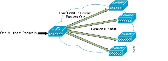
Before Cisco Unified Wireless Network Software Release 3.2, when IP multicast was enabled, the controller delivered multicast packets to WLAN clients by making copies of the multicast packets and then forwarding the packets through a unicast Lightweight Access Point Protocol (LWAPP) tunnel to each AP connected to the controller. Each multicast frame received by the controller from a VLAN on the first hop router was copied and sent over the LWAPP tunnel to each of the access points connected to it, as shown in Figure 6-1. The unicast LWAPP packet containing the multicast packet used a WLAN bitmap, which told the receiving AP which WLAN SSIDs it must forward the packet over (for example, all WLAN SSIDs associated with the incoming VLAN). When the AP received the LWAPP packet, it stripped off the outer LWAPP encapsulation and transmitted a copy to each WLAN SSID (on all radios associated to the WLAN SSID) identified in the LWAPP WLAN ID bitmask.
Note
Enabling multicast packet forwarding also enables broadcast packet forwarding in either the unicast mode or multicast mode of forwarding; the WLC still blocks the ARP broadcast from the WLAN, but because IP broadcast is simply a special cast of multicast, it is forwarded.
Figure 6-1 Multicast Forwarding Mechanism in Release 3.1 and Earlier Versions
Depending on the number of APs, the controller might need to generate up to 300 copies of each multicast packet. This mechanism is inefficient, and places a large processing burden on the controller, flooding the network with a large number of duplicate unicast packets.
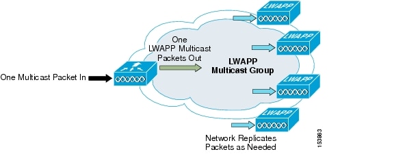
In Cisco Unified Wireless Network Software Release 3.2 and later releases, the multicast performance of the Cisco Unified Wireless Network has been optimized, by introducing a more efficient way of delivering multicast traffic from the controller to the access points. Instead of using unicast to deliver each multicast packet over the LWAPP tunnel to each access point, an LWAPP multicast group is used to deliver the multicast packet to each access point (see Figure 6-2). This allows the routers in the network to use standard multicast techniques to replicate and deliver multicast packets to the APs. For the LWAPP multicast group, the controller becomes the multicast source and the APs become the multicast receivers. For the multicast performance feature, the APs accept IGMP queries only from the router and multicast packets with a source IP address of the controller with which they are currently associated.
There are two important considerations to understand when enabling this feature: 1) enabling multicast packet forwarding either in unicast or multicast mode also enables broadcast packet forwarding, and 2) with multicast enabled, any kind of multicast packet received on the VLAN from the first hop router is transmitted over the wireless network, including HSRP hellos and all router EIGRP and PIM multicast packets. If you are using millisecond hellos with HSRP on the client VLAN, this could seriously degrade the WLAN throughput for clients.
If IP multicast is to be deployed and streamed across the wireless network, implement the following recommendations:
•
•
•
•
•
Two multicast scenarios are now described with the enhanced multicast forwarding algorithm: 1) the source of the multicast is on the wired network and streams multicast to wireless users (this is the typical scenario), and 2) a wireless user is a source of the multicast stream to both wired and wireless users.
Figure 6-2 Enhanced Multicast Forwarding Mechanism in Version 3.2
After the administrator enables multicast (multicast mode is disabled by default) and configures an LWAPP multicast group, the new multicast algorithm works in one of the following ways:
•
–
–
–
–
•
–
–
Enabling the Multicast Feature
There are two tasks involved in enabling the enhanced multicast feature: 1) enabling the underlying network infrastructure for multicast operation, and 2) enabling multicast forwarding on the controllers.
Multicast-enabled Networks
A prerequisite for using this new multicast performance functionality is that a multicast-enabled network must be configured on all routers between the controllers and the APs. A multicast-enabled network allows for an efficient way to deliver a packet to many hosts across the network. IP multicast is a bandwidth-conserving technology that reduces traffic by simultaneously delivering a single stream of information to thousands of corporate recipients. Packets are replicated as necessary at each Layer 3 point in the network. A multicast routing protocol, such as PIM, is required if there is more than one router between the controllers and the APs.
See the following URLs for more information on setting up a multicast-enabled network:
•
•
Enabling Multicast Forwarding on the Controller
Enabling multicast packet forwarding also enables broadcast packet forwarding in both unicast and multicast modes.
Because of the load that replicating multicast packets places on the controller in unicast mode, IP multicast traffic through the controller is disabled by default. WLAN clients cannot receive multicast traffic when it is disabled.
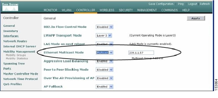
If you want to enable multicast traffic to the WLAN clients, and you have a multicast-enabled network, select multicast under Ethernet Multicast Mode to use the method where the network replicates the packets.
If you want to enable multicast traffic to the WLAN clients, and you do not have a multicast-enabled network, select unicast under Ethernet Multicast Mode to use the method where the controller replicates the packets.
Commands for Enabling Ethernet Multicast Mode via the GUI
To enable the Ethernet Multicast mode using the GUI (see Figure 6-3), follow these steps:
Step 1
Step 2
Figure 6-3 Enabling Multicast Forwarding
Commands for Enabling Ethernet Multicast Mode via the CLI
To enable the Ethernet Multicast mode using the CLI, follow these steps:
Step 1
Step 2
Use the show network command to verify the multicast mode on the controller and the show lwapp mcast command to verify the group on the AP. Other useful commands are show ip mroute and show ip igmp membership on the routers.
Note
Multicast Deployment Considerations
LWAPP Multicast Reserved Ports and Addresses
The controller blocks all multicast packets sent to any multicast group that have a destination port of 12222 through 12224. Additionally, all packets with a multicast group address equal to the controller LWAPP multicast group address are blocked at the controller. This prevents fragmented LWAPP-encapsulated packets from another controller being retransmitted (see Fragmentation and LWAPP Multicast Packets for more information).
Ensure that the multicast applications in your network do not use these reserved ports or LWAPP multicast group addresses.
Recommendations for Choosing an LWAPP Multicast Address
Cisco recommends that you assign multicast addresses from the administratively-scoped block 239/8. IANA has reserved the range of 239.0.0.0-239.255.255.255 as administratively-scoped addresses for use in private multicast domains. These addresses are similar in nature to the reserved Private IP unicast ranges (such as 10.0.0.0/8) that are defined in RFC 1918. Network administrators are free to use the multicast addresses in this range inside of their domain without fear of conflicting with others elsewhere in the Internet. This administrative or private address space should be used within the enterprise and blocked from leaving or entering the Autonomous System (AS).
Note
Cisco recommends that enterprise network administrators further subdivide this address range into smaller geographical administrative scopes within the enterprise network to limit the scope of particular multicast applications. This prevents high-rate multicast traffic from leaving a campus (where bandwidth is plentiful) and congesting the WAN links. It also allows for efficient filtering of the high bandwidth multicast to prevent it from reaching the controller and the wireless network.
Note
http://www.cisco.com/en/US/tech/tk828/technologies_white_paper09186a00802d4643.shtml.
Fragmentation and LWAPP Multicast Packets
When a controller receives a multicast packet, it LWAPP-encapsulates it using the LWAPP multicast group as a destination address and then forwards it to the APs via the management interface (source address). If the packet exceeds the MTU of the link, the controller fragments the packet into two packets and sends out both packets to the LWAPP multicast group. If another controller were to receive this LWAPP-encapsulated multicast packet via the wired network, it could re-encapsulate it, treating it as a normal multicast packet, and would then forward it to its APs.
There are two options to prevent this from happening, either of which is effective by itself: 1) you can assign all controllers to the same LWAPP multicast group address, or 2) you can apply standard multicast filtering techniques to ensure that LWAPP-encapsulated multicast packets do not reach any other controller. Table 6-1 provides the pros and cons of these two techniques.
All Controllers Have the Same LWAPP Multicast Group
To prevent the second controller from re-transmitting these LWAPP encapsulated packets, the controllers block incoming multicast packets to the LWAPP multicast group and the LWAPP reserved ports. By blocking the reserved ports, the controller blocks the first part of a fragmented packet in an encapsulated LWAPP multicast packet. However, the second packet does not contain port numbers and can be blocked only by filtering it on the multicast group address (destination address). The controller blocks any packets where the destination address is equal to the LWAPP multicast group address that is assigned to the controller.
However, assigning every controller to the same LWAPP multicast group creates other problems, although smaller. IGMP version 1 and 2 used by the APs to join the LWAPP multicast group are Any Source Multicast (ASM) and the APs receive multicast traffic from all sources of the multicast group in the network. This means that the APs receive multicast packets from all of the controllers on the network if the controllers are configured with the same multicast group address, and no multicast boundaries have been applied. One controller's multicast traffic floods out to all of the APs across the network and every AP receives (and drops, if the source address is not equal to its controller's management address) the multicast traffic that is being received from any wireless multicast client in the entire network.
Note
Controlling Multicast on the WLAN using Standard Multicast Techniques
In the past, the Time To Live (TTL) field in the IP multicast datagram was used for creating Auto-RP administrative boundaries using the ttl-threshold command. This has been superseded by the ip multicast boundary interface mode command, which filters IP multicast traffic and also AutoRP messages. Cisco recommends transitioning to, and using, the new command.
Normal boundary techniques should be used in your multicast-enabled network. These include using the ip multicast boundary interface mode command, which filters IP multicast traffic and also Auto-RP messages.
Other useful commands include the ip multicast rate-limit interface command. This command enforces low rates on the wireless VLANs. Without it, even if the network engineer filters the high rate multicast addresses, a low rate multicast address cannot exceed its rate.
Caution
A typical example on a wireless client VLAN is given below. For more information on other multicast commands for a multicast-enabled network, see the following URL: http://www.cisco.com/en/US/products/ps6552/products_ios_technology_home.html.
Filtering for multicast-enabled traffic also allows you to prevent propagation of certain worms such as the Sasser worm, which relied on the TCP and ICMP transports with multicast addresses. Blocking these types of addresses with multicast group addresses does not affect most applications because they typically use UDP or RCP for streaming.
In the following example, packets to the multicast group range 239.0.0.0 to 239.127.255.255 from any source have their packets rate limited to 128 kbps. The following example also sets up a boundary for all multicast addresses that are not in the lower administratively scoped addresses: In addition, hosts serviced by Vlan40 can join only the lower administrative groups 239.0.0.0 through 239.127.255.255.
Note
mls qos!class-map match-all multicast_trafficdescription Permit Low Rate Multicast Range of 239.0.0.0 to 239.127.0.0match access-group 101!policy-map multicastdescription Rate Limit Multicast traffic to 2.56mps with burst of 12800 bytesclass multicast_trafficpolice cir 2560000 bc 12800 be 12800 conform-action transmit exceed-action drop!interface Vlan40description To Wireless Clientsip address 10.20.40.3 255.255.255.0ip pim sparse-modeip multicast boundary 1ip igmp access-group 30standby 40 ip 10.20.40.1standby 40 preemptservice-policy output multicast!access-list 1 remark Permit Low Rate Multicast Range of 239.0.0.0 to 239.127.0.0 for multicast boundaryaccess-list 1 permit 239.0.0.0 0.127.255.255!access-list 30 remark Only Allow IGMP joins to this Multicast Group Rangeaccess-list 30 permit 239.0.0.0 0.127.255.255!access-list 101 remark Permit Low Rate Multicast Range of 239.0.0.0 to 239.127.0.0 for class-mapaccess-list 101 permit ip any 239.0.0.0 0.127.255.255How Controller Placement Impacts Multicast Traffic and Roaming
This section describes two deployments, distributed and co-located, and how they impact roaming with multicast clients. In co-located controllers that are attached to the same VLANs, such as in a data center, the multicast streams are uninterrupted when a multicast client roams from one controller to another controller.
However, the co-located deployment creates a flat multicast network. The reason co-located controllers do not affect multicast roaming is that when the multicast stream is requested from a single multicast client on a WLAN SSID, it streams out all APs on that WLAN SSID, on all radios (802.11g and 802.11a), on all controllers, even if that access point has no multicast clients associated with it that have requested the multicast traffic. If you have more than one WLAN SSID associated to the VLAN, the AP transmits the multicast packet for each WLAN SSID. Both the unicast mode LWAPP packet and the multicast mode LWAPP packet contain a WLAN bitmap that tells the receiving AP which WLAN SSIDs it must forward the packet over. When the AP receives a packet destined to the LWAPP multicast group, it strips off the outer header and handles the original multicast packet by sending a copy to each WLAN that is identified in the LWAPP WLAN id bitmask.
The distributed deployment reduces the amount of multicast traffic on the APs because, although the WLAN SSIDs are the same, the controllers are attached to different VLANs. WLAN multicast traffic depends on a client request on the VLAN of that WLC. This means that when the multicast client roams to a new controller, the client stops receiving the multicast stream unless it was already requested by a client on that WLC VLAN, or the client makes a new IGMP request. Table 6-2 lists the advantages and disadvantages of distributed and co-located deployments.
Whether a multicast client has uninterrupted streaming while roaming is best summarized by the following statement: if a multicast client roams to an AP attached to a different controller (a client moves from an access point on their anchor controller to an access point on a foreign controller), the client can receive multicast packets in only one of the following two cases:
•
•
Additional Considerations
Two areas of for additional consideration in multicast deployment are when implementing AP groups, and H-REAPs and REAPs.
AP groups allow APs on the same controller to map the same WLAN (SSID) to different VLANs, depending on the AP that a client is using. If a WLAN is roaming between APs in different groups, the multicast session would break in the same manner as if a client roams between APs connected to different WLCs on separate VLANs.
REAP and H-REAP APs allow the local termination of WLANs at the network edge rather than at the WLC, and the multicast behavior is controlled at that edge. If an H-REAP WLAN is terminated on a WLC and multicast is enabled on that WLC, multicast is delivered to that H-REAP WLAN if the LWAPP multicast group is allowed to extend to the H-REAP network location.
Note