Downloads |
 Feedback Feedback
|
Table Of Contents
Installing Field-Replaceable Units in Cisco 7100 Series VPN Routers
Electrical Equipment Guidelines
Electrostatic Discharge Prevention
Installing the Rack-Mount and Cable-Management Brackets
Attaching the Cable-Management Bracket
Attaching the Rack-Mount Brackets
Removing the Router from the Rack
Installing Field-Replaceable Units in Cisco 7100 Series VPN Routers
Product Numbers: ACS-7100-RMK=, MEM-7120/40-64P=, MEM-7120/40-64S=, MEM-7120/40-128S=, MEM-7120/40-192S=
This document describes installation procedures for field-replaceable units (FRUs) for Cisco 7100 series routers and contains the following sections:
•
Installing the Rack-Mount and Cable-Management Brackets
•
•
Use this document in conjunction with the Cisco 7100 Series VPN Router Installation and Configuration Guide publication and the Regulatory Compliance and Safety Information for Cisco 7100 Series VPN Routers document.
Installation instructions for modular port adapters can be found in the individual document that ships with the port adapter. For example, if you ordered a PA-4E Ethernet port adapter, the PA-4E Ethernet 10BaseT Port Adapter Installation and Configuration note is shipped with the router.
Installation instructions for the Flash Disk can be found in the Using the Flash Disk document that shipped with the router.
Warning
Required Tools
You need the following tools and equipment:
•
•
•
•
Safety Recommendations
For international agency compliance, safety, and statutory information for Cisco 7100 series routers, refer to the Regulatory Compliance and Safety Information for Cisco 7100 Series VPN Routers document that shipped with the router.
Any device that uses electricity must be handled carefully; follow these guidelines to ensure general safety:
•
•
Warning
•
•
•
•
•
•
•
•
•
•
Warning
Electrical Equipment Guidelines
Warning
Warning
Follow these guidelines when you work on equipment powered by electricity.
•
•
•
•
•
Warning
Warning
•
•
•
•
•
•
•
•
Warning
In addition, use the guidelines that follow when working with any equipment that is disconnected from a power source, but still connected to telephone wiring or other network cabling.
•
•
•
•
Warning
Electrostatic Discharge Prevention
Electrostatic discharge (ESD) can damage equipment and impair electrical circuitry. ESD damage occurs when electronic components are improperly handled and can result in complete or intermittent failures.
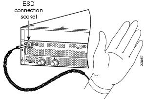
Always follow ESD-prevention procedures when you remove and replace components. Ensure that the chassis is electrically connected to earth ground. Wear an ESD-preventive wrist strap, ensuring that it makes good skin contact. Connect the grounding clip to an unpainted surface of the chassis frame to safely ground unwanted ESD voltages. To guard against ESD damage and shocks, the wrist strap and cord must operate properly. If no wrist strap is available, ground yourself by touching the metal part of the chassis.
Caution
Figure 1 Attaching an Electrostatic Discharge Wrist Strap
Chassis Lifting Guidelines
A fully configured Cisco 7100 series router weighs approximately 32 pounds (14.5 kg). The chassis is not intended to be moved frequently. Before you install the router, ensure that your site is properly prepared so you can avoid having to move the chassis later to accommodate power sources and network connections.
Whenever you lift the chassis or any heavy object, follow these guidelines:
•
•
•
•
•
Warning
Site Requirement Guidelines
Warning
The environmental monitoring functionality in the router protects the system and components from potential damage from overvoltage and overtemperature conditions. To ensure normal operation and avoid unnecessary maintenance, plan your site configuration and prepare your site before installation. After installation, make sure the site maintains an ambient temperature of 32°F through 104°F (0°C through 40°C), and keep the area around the chassis as free from dust as is practical.
Planning a proper location for the router and the layout of your equipment rack or wiring closet is essential for successful system operation. Equipment placed too close together or inadequately ventilated can cause system overtemperature conditions. In addition, chassis panels made inaccessible by poor equipment placement can make system maintenance difficult. Following are precautions that can help avoid problems during installation and ongoing operation.
Follow these general precautions when planning your equipment locations and connections:
•
•
•
•
Rack-Mounting Guidelines
The rack-mounting hardware included with router is suitable for most 19- or 23-inch equipment racks and telco-type racks. To easily access the interface cables while the router is installed in a rack, make certain you have access to the rear of the router.
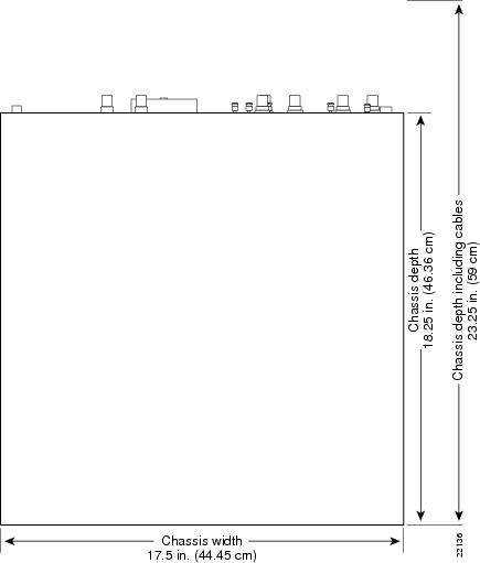
Before using a particular rack, check for obstructions (such as a power strip) that could impair rack-mount installation. If a power strip does impair a rear rack-mount installation, remove the power strip before installing the router in the rack, and then replace it after the chassis is installed. As an alternative, you can mount the router on an equipment shelf provided that the rack dimensions allow you to secure the router to the shelf, and the overall configuration permits safe installation and access. However, we recommend rack-mounting the router. shows the Cisco 7100 series router footprint and outer dimensions.
To use the rack-mounting hardware provided with the router, consider the following guidelines:
•
•
•
Figure 2 Cisco 7100 Series Router Footprint and Outer Dimensions
When planning your rack installation, consider the following guidelines:
•
Caution
•
•
•
•
•
•
Note
Power Connection Guidelines
Follow these precautions and recommendations when planning power connections to a Cisco 7100 series router:
•
•
•
•
Warning
•
Warning
Note
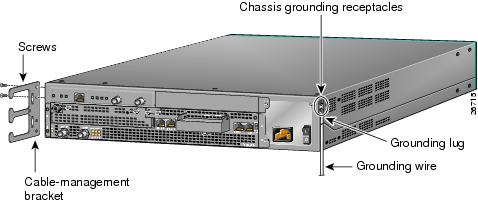
The chassis employs two threaded chassis grounding receptacles, located on the rear of the chassis, which are intended to be bonded directly to the central offices or other interior ground system. The chassis ground requires M3.5 screws, which are included. (For instructions on how to properly ground the chassis, refer to Chapter 3, "Installing Cisco 7100 Series Routers" in the Cisco 7100 Series VPN Router Installation and Configuration Guide.
•
Note
Installing the Rack-Mount and Cable-Management Brackets
The rack-mount and cable-management kit for the Cisco 7100 series routers consists of rack-mount brackets and a cable-management bracket that are designed for mounting your router in 19- or 23-inch, 4-post or telco-type equipment racks.
This section describes how to attach the rack-mount and cable-management brackets to the router. For more information about cabling the router, refer to Chapter 3, "Installing Cisco 7100 Series Routers" in the Cisco 7100 Series VPN Router Installation and Configuration Guide.
Attaching the Cable-Management Bracket
To install the cable-management bracket on the router, complete the following steps:
Step 1
Note
Step 2
Step 3
Figure 3 Attaching the Cable-Management Bracket to the Chassis
This completes the steps for installing the cable-management bracket on a Cisco 7100 series router. Carefully lace interface cables through the cable-management bracket as needed.
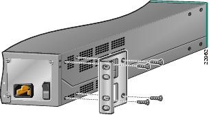
Attaching the Rack-Mount Brackets
To install the chassis in a rack:
Step 1
Step 2
Note
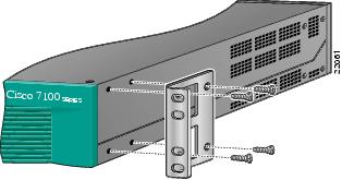
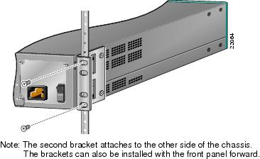
Figure 4 Standard Bracket Installation—Front Panel Forward
Figure 5 Standard Bracket Installation—Rear Panel Forward
Step 3
Figure 6 Attaching the Chassis to the 19-Inch Rack—Rear Panel Forward
Note
Step 4
Step 5
Step 6
Removing the Router from the Rack
This section describes how to remove the router from the rack. To gain access to the SDRAM DIMMs, you must power off the router and remove it from the rack.
To remove the router from the rack:
Step 1
Note
Step 2
Step 3
Step 4
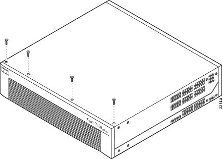
Removing the Chassis Cover
This section describes how to remove the chassis cover from the router. To gain access to the SDRAM DIMMs, you must open the router chassis.
To remove the chassis cover:
Step 1
Note
Step 2
Step 3
Step 4
Figure 7 Removing the Chassis Cover Screws
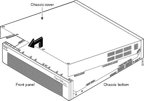
Step 5
Figure 8 Removing the Chassis Cover
Replacing SDRAM DIMMs
This section describes how to replace the SDRAM DIMMs in the router. You might need to upgrade the SDRAM DIMMs for the following reasons:
•
•
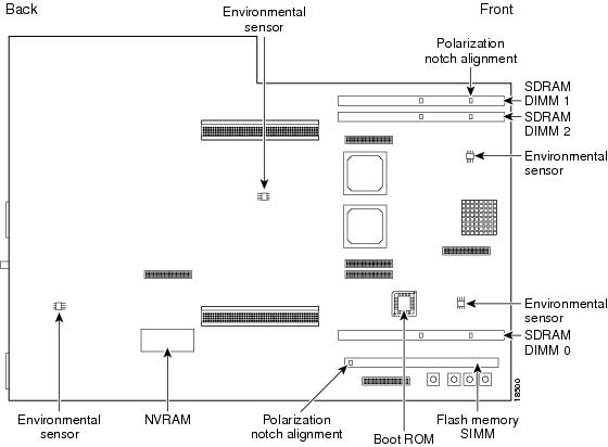
The network processor card contains three sockets for SDRAM DIMMs (see ):
•
•
Figure 9 Locating the SDRAM DIMMs
To replace the SDRAM DIMMs:
Step 1
Note
Step 2
Step 3
Step 4
Step 5
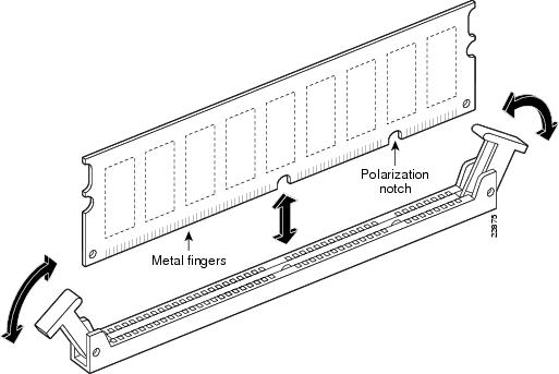
Figure 10 Opening the DIMM Socket Tabs and Removing an SDRAM DIMM
Step 6
Caution
Step 7
Tips
Caution
Step 8
Step 9
•
(a)
(b)
(c)
•
(a)
(b)
Replacing the Chassis Cover
This section describes replacing the chassis cover on the router. You must remove the chassis cover to gain access to the SDRAM DIMMs.
To replace the chassis cover:
Step 1
Step 2
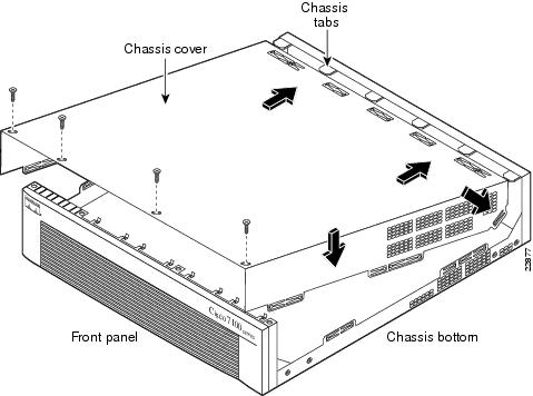
Step 3
•
•
•
When the chassis cover is properly assembled, no tabs are visible.
Step 4
Step 5
Step 6
Figure 11 Replacing the Chassis Cover
Step 7
Installing and Using PC Cards
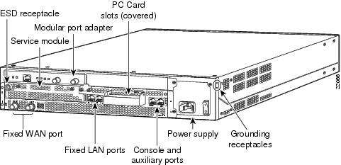
This section contains instructions for installing and removing a Flash Disk or Flash memory PC Card in Cisco 7100 series routers. Cisco 7100 series routers support up to two Flash Disks or Flash memory cards in the PC Card slots as shown in .
Figure 12 PC Card Slot Location—Cisco 7120 Router
Note
Note
The installation procedure is generic and can be used for any PC Card (Flash Disk or Flash memory card) in either PC Card slot position (slot 0 or slot 1) for any Cisco 7100 series router model. You do not need to power off the system to insert or eject a PC Card.
To install and eject a PC Card in a Cisco 7100 series router:
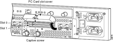
Step 1
PC Card slot has a cover that is secured with a captive screw. (See .)Figure 13 Removing the PC Card Slot Cover in a Cisco 7100 Series Router
Step 2
Step 3
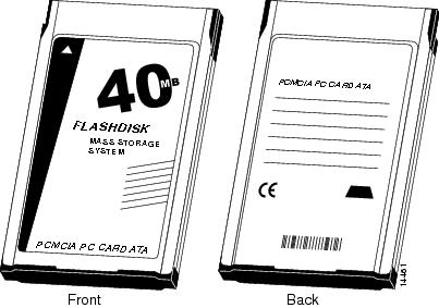
Note
Figure 14 Flash Disk PC Card
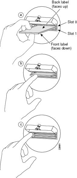
Note
Figure 15 Installing and Ejecting a PC Card
Step 4
Step 5
Step 6
Cisco Connection Online
Cisco Connection Online (CCO) is Cisco Systems' primary, real-time support channel. Maintenance customers and partners can self-register on CCO to obtain additional information and services.
Available 24 hours a day, 7 days a week, CCO provides a wealth of standard and value-added services to Cisco's customers and business partners. CCO services include product information, product documentation, software updates, release notes, technical tips, the Bug Navigator, configuration notes, brochures, descriptions of service offerings, and download access to public and authorized files.
CCO serves a wide variety of users through two interfaces that are updated and enhanced simultaneously: a character-based version and a multimedia version that resides on the World Wide Web (WWW). The character-based CCO supports Zmodem, Kermit, Xmodem, FTP, and Internet e-mail, and it is excellent for quick access to information over lower bandwidths. The WWW version of CCO provides richly formatted documents with photographs, figures, graphics, and video, as well as hyperlinks to related information.
You can access CCO in the following ways:
•
•
•
•
•
For a copy of CCO's Frequently Asked Questions (FAQ), contact cco-help@cisco.com. For additional information, contact cco-team@cisco.com.
Note
Documentation CD-ROM
Cisco documentation and additional literature are available in a CD-ROM package, which ships with your product. The Documentation CD-ROM, a member of the Cisco Connection Family, is updated monthly. Therefore, it might be more current than printed documentation. To order additional copies of the Documentation CD-ROM, contact your local sales representative or call customer service. The CD-ROM package is available as a single package or as an annual subscription. You can also access Cisco documentation on the World Wide Web at http://www.cisco.com, http://www-china.cisco.com, or http://www-europe.cisco.com.
If you are reading Cisco product documentation on the World Wide Web, you can submit comments electronically. Click Feedback in the toolbar and select Documentation. After you complete the form, click Submit to send it to Cisco. We appreciate your comments.
78-6344-02