Feedback Feedback
|
Table Of Contents
Installing and Removing the Power Supply in Cisco 7100 Series Routers
Preventing Electrostatic Discharge Damage
Obtaining Technical Assistance
Installing and Removing the Power Supply in Cisco 7100 Series Routers
Product Numbers: PWR-7100-AC=, PWR-7100/2=
This document describes how to replace an existing AC power supply. It also includes the following sections:
•
Obtaining Technical Assistance
Safety Recommendations
Follow these guidelines to ensure general safety:
•
•
•
•
•
•
Safety Warnings
Safety warnings appear throughout this publication in procedures that, if performed incorrectly, may harm you. A warning symbol precedes each safety warning.
Safety with Electricity
Warning
Warning
Warning
Warning
Warning
Follow these guidelines when working on equipment powered by electricity:
•
•
–
–
•
•
•
Preventing Electrostatic Discharge Damage
Electrostatic discharge (ESD) can damage equipment and impair electrical circuitry. It occurs when electronic printed circuit cards are improperly handled and can result in complete or intermittent failures. Always follow ESD prevention procedures when removing and replacing cards. Ensure that the chassis is electrically connected to earth ground. Wear an ESD-preventive wrist strap, ensuring that it makes good skin contact. Connect the clip to an unpainted surface of the chassis frame to safely channel unwanted ESD voltages to ground. To properly guard against ESD damage and shocks, the wrist strap and cord must operate effectively. If no wrist strap is available, ground yourself by touching the metal part of the chassis.
Caution
Required Tools and Equipment
The power supply kits include the following:
•
•
To remove or install the power supplies, you will also need the following tools and equipment (which are not included):
•
•
•
•
Removing the Chassis Cover
This section describes how to remove the chassis cover from the router. To gain access to the power supply, you must open the router chassis.
Warning
Warning
Warning
Warning
Warning
To remove the chassis cover, complete the following steps:
Step 1
Note
Step 2
Step 3
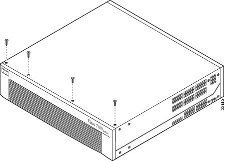
Step 4
Figure 1 Removing the Chassis Cover Screws
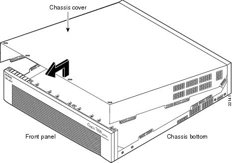
Step 5
Figure 2 Removing the Chassis Cover
Removing the Power Supply
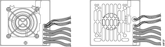
Note
Figure 3 Cisco 7140 power supplies
This section describes how to remove the power supply. Note the following safety warnings before you remove the power supply:
Warning
Warning
Warning
Warning
Warning
To remove the power supply, complete the following steps:
Step 1
Step 2
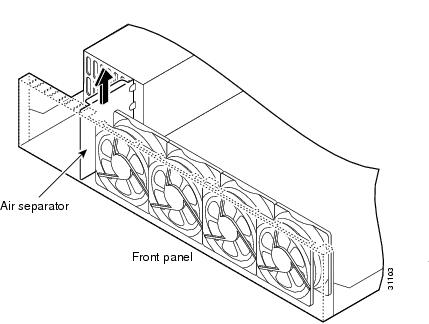
Step 3
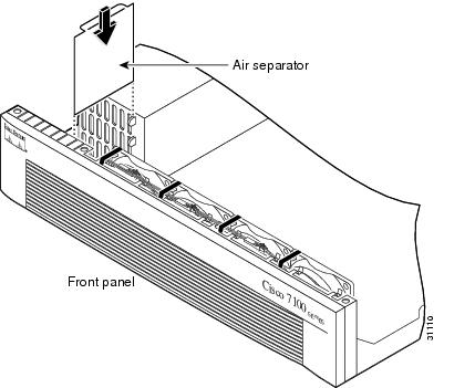
Figure 4 Removing the Air Separator
Step 4
Step 5
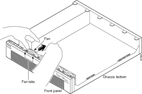
Figure 5 Pulling the Fan Away from the Tabs
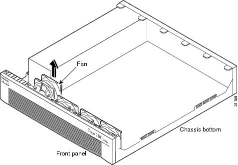
Figure 6 Removing the Fan
Step 6
Caution
Step 7
Note
Table 1 Fan Wiring Colors
1 (closest to power supply)
Purple and black
2
Green and black
3
Blue and black
4 (farthest away from power supply)
Brown and black
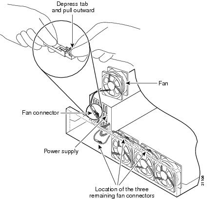
Figure 7 Disconnecting the Fan Cable
Step 8
Step 9
Note
Step 10
Step 11
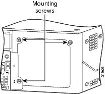
Figure 8 Power Supply Mounting Screws
Step 12
Step 13
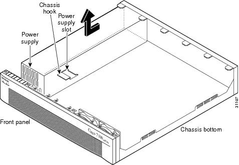
Figure 9 Lifting the Power Supply Out of the Chassis
Warning
Installing the Power Supply
To install the power supply, complete the following steps:
Step 1
Step 2
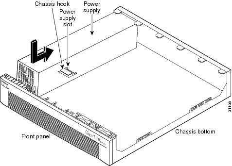
Figure 10 Inserting the Power Supply in the Chassis
Step 3
Step 4
Step 5
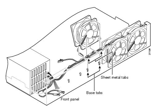
Figure 11 Routing the Fan Cables
Step 6
Step 7
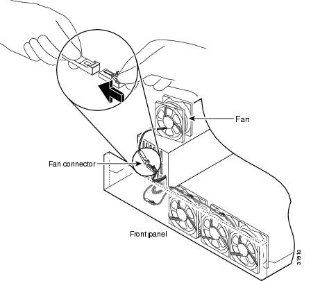
Figure 12 Reconnecting the Fan Cables
Step 8
Step 9
Figure 13 Correct Fan Cable Routing
Step 10
Figure 14 Replacing the Air Separator
Step 11
Rerouting the Fan Wiring
If the fan wiring in your router is not routed on top of the fans, you need to reroute the fan wiring. This will make future power supply replacement easier.
To reroute the fan wiring, complete the following steps:
Step 1
Step 2
Figure 15 Pulling the Fan Away from the Tabs
Figure 16 Removing the Fan
Step 3
Caution
Step 4
Note
Figure 17 Disconnecting the Fan Cable
Step 5
Step 6
Step 7
Note
Step 8
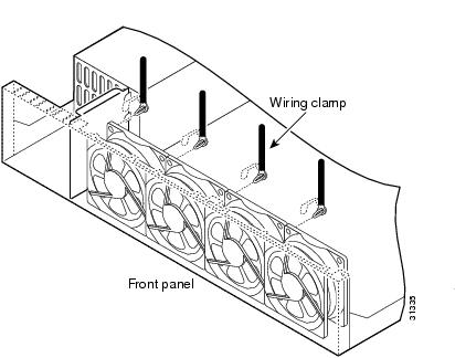
Figure 18 Inserting Cable Clamp onto fan
Step 9
Step 10
Step 11
Figure 19 Reconnecting the Fan Cables
Replacing the Chassis Cover
This section describes replacing the chassis cover on the router. You must remove the chassis cover to gain access to the power supply.
To replace the chassis cover, complete the following steps:
Step 1
Step 2
Step 3
•
•
•
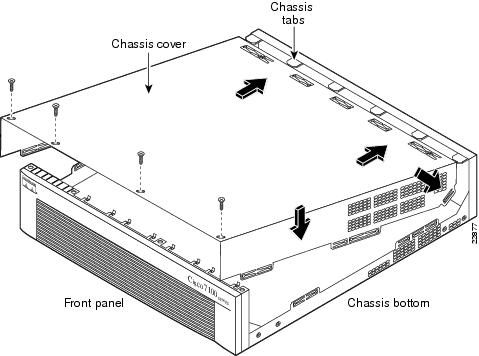
When the chassis cover is properly assembled, no tabs are visible.
Step 4
Step 5
Step 6
Figure 20 Replacing the Chassis Cover
Step 7
Obtaining Documentation
World Wide Web
You can access the most current Cisco documentation on the World Wide Web at http://www.cisco.com, http://www-china.cisco.com, or http://www-europe.cisco.com.
Documentation CD-ROM
Cisco documentation and additional literature are available in a CD-ROM package, which ships with your product. The Documentation CD-ROM is updated monthly. Therefore, it is probably more current than printed documentation. The CD-ROM package is available as a single unit or as an annual subscription.
Ordering Documentation
Registered CCO users can order the Documentation CD-ROM and other Cisco Product documentation through our online Subscription Services at http://www.cisco.com/pcgi-bin/subcat/kaojump.cgi.
Nonregistered CCO users can order documentation through a local account representative by calling Cisco's corporate headquarters (California, USA) at 408 526-4000 or, in North America, call 800 553-NETS (6387).
Obtaining Technical Assistance
Cisco provides Cisco Connection Online (CCO) as a starting point for all technical assistance. Warranty or maintenance contract customers can use the Technical Assistance Center. All customers can submit technical feedback on Cisco documentation using the web, e-mail, a self-addressed stamped response card included in many printed docs, or by sending mail to Cisco.
Cisco Connection Online
Cisco continues to revolutionize how business is done on the Internet. Cisco Connection Online is the foundation of a suite of interactive, networked services that provides immediate, open access to Cisco information and resources at anytime, from anywhere in the world. This highly integrated Internet application is a powerful, easy-to-use tool for doing business with Cisco.
CCO's broad range of features and services helps customers and partners to streamline business processes and improve productivity. Through CCO, you will find information about Cisco and our networking solutions, services, and programs. In addition, you can resolve technical issues with online support services, download and test software packages, and order Cisco learning materials and merchandise. Valuable online skill assessment, training, and certification programs are also available.
Customers and partners can self-register on CCO to obtain additional personalized information and services. Registered users may order products, check on the status of an order and view benefits specific to their relationships with Cisco.
You can access CCO in the following ways:
•
•
•
–
–
You can e-mail questions about using CCO to cco-team@cisco.com.
Technical Assistance Center
The Cisco Technical Assistance Center (TAC) is available to warranty or maintenance contract customers who need technical assistance with a Cisco product that is under warranty or covered by a maintenance contract.
To display the TAC web site that includes links to technical support information and software upgrades and for requesting TAC support, use www.cisco.com/techsupport.
To contact by e-mail, use one of the following:
In North America, TAC can be reached at 800 553-2447 or 408 526-7209. For other telephone numbers and TAC e-mail addresses worldwide, consult the following web site: http://www.cisco.com/warp/public/687/Directory/DirTAC.shtml.
Documentation Feedback
If you are reading Cisco product documentation on the World Wide Web, you can submit technical comments electronically. Click Feedback in the toolbar and select Documentation. After you complete the form, click Submit to send it to Cisco.
You can e-mail your comments to bug-doc@cisco.com.
To submit your comments by mail, for your convenience many documents contain a response card behind the front cover. Otherwise, you can mail your comments to the following address:
Cisco Systems, Inc.
Document Resource Connection
170 West Tasman Drive
San Jose, CA 95134-9883We appreciate and value your comments.