Downloads |
 Feedback Feedback
|
Table Of Contents
VPN Group Configuration Dialog Box
VPN Group Configuration General Tab
VPN Group Configuration IKE Configuration Tab
VPN Group Configuration Manual Tab
VPN Group Configuration IP Connection Tab
VPN Group Configuration IP Filters Tab
VPN Group Configuration IPX Connection Tab
VPN Group Configuration IPX Filters Tab
VPN Group Configuration Rollover Tab
Alternate VPN 5000 Concentrator Addresses
VPN Group Configuration SecurID Tab
VPN Group Configuration DNS Redirection Tab
VPN Group Configuration WINS Redirection Tab
VPN User Configuration Dialog Box
STEP/STAMP Authentication Secret
Allowed Authentication Protocol for PPTP Client Connections
VPN Client Tunnels
VPN Group Configuration Dialog Box
To access this dialog box (Figure 7-1), select VPN Group Configuration from the Device View.
Figure 7-1 VPN Group Configuration Dialog Box and General Tab
This dialog box displays and allows editing of all VPN Group Configurations for an VPN 5000 concentrator. VPN group configurations define tunneling profiles for a group of one or more VPN 5000 concentrator users.
Table 7-1 lists the maximum number of VPN group configurations allowed per device type.
Table 7-1 Maximum VPN Group Configurations
.
Cisco VPN 5001 Concentrator
100
Cisco VPN 5002 Concentrator
Cisco VPN 5008 Concentrator
1,000
1,000
Current VPN Group
This edit box allows a VPN group configuration to be selected. Any changes made in the tab windows will be stored to the selected group configuration.
New
Clicking on this button will bring up a dialog box which allows the creation of a new group configuration.
Rename
Clicking on this button will bring up a dialog box to allow the currently selected VPN group configuration to be renamed.
Delete
Clicking on this button will delete the presently selected group configuration.
VPN Group Configuration General Tab
Bind To
This drop-down menu allows the selection of an interface on the device. The interface selected will act as the local end point for the tunnels defined by this configuration.
Some VPN devices may only have one interface available for this function. In this case, the pull-down will not have any other choices available.
Max Connections
This is the maximum number of simultaneous client connections using this configuration which will be allowed by the device.
This setting can be used to limit the number of connections for certain classes of users by assigning users to different group configurations. This number may not exceed the maximum number of tunnel connections supported by the device. If the sum of the Max Connections for all VPN Group sections exceeds the maximum number of tunnel connections supported by the device, tunnel connections will be served on a first-come, first-served basis.
Keep Alive Interval
This is the number of seconds between keep-alive packets sent to each connected client by the device.
Clients which do not answer these packets and/or generate other traffic within several keep-alive intervals will have their connections shut down.
Keep-alive packets are only sent in the case where no other traffic has been received from the client in the specified number of seconds.
Inactivity Timeout
This is the number of seconds the device will wait without receiving any traffic from a client belonging to this VPN Group configuration before ending the tunnel session.
Keep-alive packets and ICMP (ping) traffic do not affect this timeout. This prevents users from using ping to keep their tunnels up. The range is 1 to 65535 seconds. The default of 0 seconds means there is no timeout.
Minimum Client Version
This places a limit on the VPN Client Software version number which will be allowed.
•
A value of 0 or 1 will allow any software version number.
•
•
•
Allow L2TP
This checkbox enables L2TP connections for client sessions using this configuration.
Allow PPTP
PPTP is currently not supported.
Encrypt Method
This pulldown menu specifies which encryption method will be used for PPTP clients. PPTP is currently not supported.
Exclude Local LAN
This checkbox specifies whether remote client LAN traffic will be tunneled.
•
The user login in the VPN Client software must also have the Exclude Local LAN from Tunnel checkbox checked.
SLA Enable Client
This checkbox specifies that Service Level Agreement (SLA) information will be gathered for tunnel sessions using this VPN Group Configuration. SLA measures the speed of traffic across the tunnel and can be used to ensure that service guarantees are met.
SNMP is used to display the gathered information. This requires that SNMP be enabled in the Advanced SNMP dialog box. Refer to "General Configuration Windows," for more information on SNMP Configuration.
Tunnel NetBT
If this box is checked, all traffic using Microsoft's networking protocol, Windows NetBT, will be tunneled.
VPN Group Configuration IKE Configuration Tab
To access this dialog box (Figure 7-2), click the IKE Configuration tab in the VPN Group Configuration dialog box.
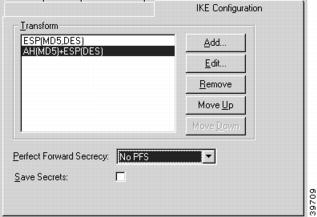
Figure 7-2 VPN Group Configuration IKE Configuration Tab
Transform
This specifies the protection types and algorithms that will be used for IKE tunnel sessions for this group configuration. Each option is a protection piece which specifies authentication and/or encryption parameters.
Use the Move Up and Move Down buttons to arrange the priority of the protection options.
Perfect Forward Secrecy
Perfect Forward Secrecy (PFS) allows you to add an additional security parameter to tunnel sessions. PFS means that every time encryption and/or authentication key are computed, a new Diffie-Hellman Key Exchange is included.
Diffie-Hellman Key Exchange uses a complex algorithm and public and private keys to encrypt and then decrypt tunneled data. Adding PFS to a tunneled session greatly increases the difficulty of finding the session keys used to encrypt a VPN session. It also means that even if the keys are somehow cracked, only a portion of the traffic is recoverable.
•
•
•
•
•
Save Secrets
This checkbox allows all users assigned to this particular VPN Group Configuration to save their shared secret to disk. If checked, users in this Group will not be prompted for their secret after the first session.
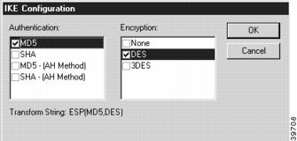
To add, edit, or remove a Transform, you must access the IKE Configuration dialog box by selecting the Add..., Edit..., or Remove... buttons on the IKE Configuration tab of the VPN Group Configuration dialog box (Figure 7-3).
Figure 7-3 IKE Configuration Dialog Box
Authentication
This set of checkboxes specifies the authentication algorithm to be used for the tunnel session. MD5 is the Message-Digest 5 hash algorithm. SHA is the Secure Hash Algorithm.
Choosing either of the top two checkboxes means that the Encapsulating Security Payload (ESP) header will be used to encrypt and authenticate packets.
Choosing either of the bottom two checkboxes specifies that the Authentication Header (AH) will be used to authenticate packets.
Encryption
This set of checkboxes specifies the encryption algorithm to be used for the tunnel session.
DES (Data Encryption Standard) uses a 56-bit key to scramble the data. 3DES uses three different keys and three applications of the DES algorithm to scramble the data.
You may choose only one authentication and one encryption method. The default setting of ESP (MD5,DES) is recommended for most setups.
VPN Group Configuration Manual Tab
To access this dialog box (Figure 7-4), click the Manual tab in the VPN Group Configuration dialog box.
Figure 7-4 VPN Group Configuration Manual Tab
Encryption Method
This drop-down menu allows the selection of the encryption algorithm for non-IKE client sessions for this group configuration.
•
•
•
•
•
PLE, DES56 and 3DES all require that an Encryption Secret be configured for each user in the VPN Users dialog box. Some VPN devices may not allow 3DES as an option.
VPN Group Configuration IP Connection Tab
To access this dialog box (Figure 7-5), click the IP Connection tab in the VPN Group Configuration dialog box.
Figure 7-5 VPN Group Configuration IP Connection Tab
Start IP Address
The Start IP Address specifies the first IP address to be assigned to client sessions under this configuration. This start address will be incremented by one for each new client session, until the Max Connections limit (specified using the General Tab) is reached. The IP address is freed when the client is finished.
Each of the addresses thus generated must be a valid, unique, and unused IP address. Also, these addresses must not conflict with any networks specified in other VPN Group configuration or with any other IP address within the server.
These addresses must be on the internal TCP/IP network (i.e., for an VPN 5000 concentrator, on the same network as Ethernet 0 or a subinterface thereof).
There is no default value for the Start IP Address or Local IP Net. In order for IP-in-IP tunneling to operate with this VPN Group configuration, a group of local IP addresses must be set. Use the Start IP Address, the Local IP Net, or configure a Radius server to serve the addresses (see the "Assign IP Radius" section).
Local IP Net
This edit box sets the local network or subnet to be assigned to client sessions under this configuration. For each new client session, an available IP address from this network or subnet is assigned to that session, until the Max Connections limit (specified using the General tab) is reached. The IP address is freed when the client session is finished.
This network or subnet must be unused and completely unique in the IP network to which the concentrator is connected (i.e., not part of any Class C network in use) and may not conflict with address ranges specified in other group configurations. The mask may be between 8 and 30 bits.
The address should be entered as four decimal numbers separated by periods (e.g. 198.238.9.1). The part of this address which identifies the network segment is determined by the size of the mask, specified in bits.
If Local IP Net is selected, either a dynamic routing protocol or static routes must be configured into the controlling router (e.g., the firewall) in order for traffic to find the Local IP Net.
Assign IP Radius
This checkbox specifies whether a RADIUS server can be used to assign IP addresses to VPN users.
•
•
For more information on RADIUS configuration, see"General Configuration Windows."
Allow Connections To
This scrolling list displays the IP networks which the client will be told are reachable via the tunnel.
Any communications with an address which is part of one of the networks in the list will be tunneled. Communications with any other addresses will occur normally, without tunneling.
Add
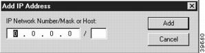
Clicking on this button will bring up a dialog box (Figure 7-6), which allows an IP network address and mask size to be entered.
Figure 7-6 Add IP Address Dialog Box
The part of this address which identifies the network segment is determined by the size of the mask, specified in bits. For example, an entry of 192.168.32.0/19 would specify that traffic with all IP addresses from 192.168.32.1 through 192.168.63.255 will be tunneled. As a special case, the entry, 0.0.0.0/0, specifies that all IP traffic should be tunneled. To tunnel to only a single host, specify 32 in the bits portion.
Following convention, mask values in the VPN 5000 Manager are generally entered as decimal numbers separated by periods (e.g. 255.255.255.0) where both the network portion and the host portion of an address are significant. Entry of mask size in bits is an alternative but equivalent way of specifying the size of the network portion of the IP address when only that portion is significant to the function being performed.
Edit
Clicking on this button brings up a dialog box which allows editing of a previously entered network and mask.
Remove
This button removes a network/mask entry from the list.
VPN Group Configuration IP Filters Tab
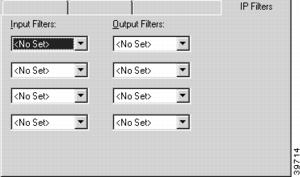
To access this dialog box (Figure 7-7), click the IP Filters tab in the VPN Group Configuration dialog box.
Figure 7-7 VPN Config IP Filters Tab
Input Filters
These pulldowns allow the selection of previously created filter scripts which will be applied to tunnel packets coming into the device from users who are connected according to the selected configuration.
Up to four separate filters may be selected.
Output Filters
These pulldowns allow the selection of previously created filter scripts which will be applied to tunnel packets sent out of the device to users who are connected according to the selected configuration.
Up to four separate filters may be selected.
IP Filters are created using the TCP/IP Filter Editor. For more information on creating and editing IP Filters, refer to "TCP/IP Filtering."
VPN Group Configuration IPX Connection Tab
To access this dialog box (Figure 7-8), click the IPX Connection tab in the VPN Group Configuration dialog box.
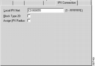
Figure 7-8 VPN Config IPX Connection Tab
Local IPX Net
This edit box specifies the entry of the first local IPX network number to be assigned to client sessions under this configuration. This address will be incremented by one for each new client session, until the Max Connection limit (specified on the General Tab) is reached. When a client is connected to the device, the first available IPX address from this range is assigned to that session. The IPX address is freed when the client session is finished.
Each of the addresses thus generated must be a valid, unique and unused IPX address. Also, these addresses must not conflict with any networks specified in other VPN Group configurations or with any other IPX address within the server.
There is no default value for the Local IPX Net. In order for IPX-in-IP tunneling to operate with this VPN Group configuration, a group of local IPX addresses must be set using either the Local IPX Net, or a RADIUS server must be configured to serve the addresses (see the "Assign IPX Radius" section).
Block Type 20
In order for certain protocol implementations, like NetBIOS, to function in the NetWare environment, routers must allow a broadcast packet to be propagated throughout an internet. The IPX Packet Type 20 is designated to perform broadcast propagation for these protocols. This checkbox specifies whether IPX Packet Type 20 should be rebroadcast through the tunnel.
•
•
Assign IPX Radius
This checkbox specifies whether a RADIUS server can be used to assign IPX addresses to VPN users.
•
•
VPN Group Configuration IPX Filters Tab
To access this dialog box (Figure 7-9), click the IPX Filters tab in the VPN Group Configuration dialog box.
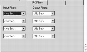
Figure 7-9 VPN Group Configuration IPX Filters Tab
Input Filters
These pulldowns allow the selection of previously created filter scripts which will be applied to tunnel packets coming into the device from users who are connected according to the selected configuration.
Up to four separate filters may be selected.
Output Filters
These pulldowns allow the selection of previously created filter scripts which will be applied to tunnel packets sent out of the device to users who are connected according to the selected configuration.
Up to four separate filters may be selected.
IPX Filters are created using the IPX Filter Editor. For more information on creating and editing IPX Filters, refer to "IPX Filtering.".
VPN Group Configuration Rollover Tab
To access this dialog box (Figure 7-10), click the Rollover tab in the VPN Group Configuration dialog box.
Figure 7-10 VPN Group Configuration Rollover Tab
Alternate VPN 5000 Concentrator Addresses
This list displays all entered alternate concentrator addresses. If an alternate address (or addresses) has been set, a concentrator which is full will be able to roll a client over to the specified alternate server. The IP address should be in standard dotted-decimal notation.
VPN Group Configuration SecurID Tab
To access this dialog box (Figure 7-11), click the SecurID tab in the VPN Group Configuration dialog box.
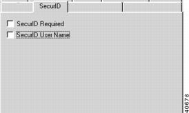
Figure 7-11 VPN Group Configuration SecurID Tab
SecurID Required
Check this box to specify that all users assigned to this VPN Group configuration will undergo SecurID authentication. SecurID is Security Dynamic's proprietary system which requires ACE/Server software and SecurID tokens to perform dynamic two-factor authentication.
SecurID User Name
Check this box if the VPN user name will also serve as the SecurID user name. If this box is checked, all users assigned to this VPN Group configuration will be prompted for their SecurID user name for authentication. If unchecked, the names for each user entered in the concentrator and the ACE/Server must be the same.
VPN Group Configuration DNS Redirection Tab
To access this dialog box (Figure 7-12), click the DNS Redirection tab in the VPN Group Configuration dialog box.
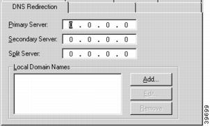
Figure 7-12 VPN Group Configuration DNS Redirecton Tab
Primary Server
The primary server specifies the primary IP address of a DNS server. If a Primary Server has been set, then the VPN Client will tunnel all DNS queries to the concentrator and the concentrator will take all DNS queries bound for the client's primary DNS server and send them to the specified address. The IP address should be in standard dotted-decimal notation.
Secondary Server
The secondary server specifies the IP address of a backup DNS server. A primary server must be specified before a secondary server is chosen. The IP address should be in standard dotted-decimal notation.
Split Server
The split server specifies the IP address of a "split" DNS server. This is useful for setups where queries for internal names are handled by one server (the primary server) while queries for external names are handled by another server (the "split" server). The IP address should be in standard dotted-decimal notation.
Local Domain Names
This list specifies the domain names that will be compared to the name in DNS queries to the DNS server in order to determine whether the query is for an internal or external domain.
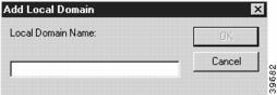
To add or modify the Local Domain Names, click on the appropriate button to access the Add Local Domain dialog box (Figure 7-13).
Figure 7-13 Add Local Domain Dialog Box
Local Domain Names can be between 1 and 255 characters in length.
VPN Group Configuration WINS Redirection Tab
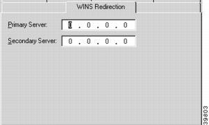
To access this dialog box (Figure 7-14), click the WINS Redirection tab in the VPN Group Configuration dialog box.
Figure 7-14 VPN Group Configuration WINS Tab
Primary Server
The primary server specifies the primary IP address of a WINS server. If a Primary Server has been set, then the VPN Client software will tunnel all WINS queries to the concentrator and the concentrator will take all WINS queries bound for the client's primary WINS server and send them to the specified address. The IP address should be in standard dotted-decimal notation.
Secondary Server
The secondary server specifies the IP address of a backup WINS server. A primary server must be specified before a secondary server is chosen. The IP address should be in standard dotted-decimal notation.
VPN User Configuration Dialog Box
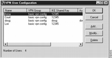
You can access the VPN User Configuration dialog box (Figure 7-15) by selecting VPN User Configuration from the Device View. This dialog box displays all VPN users configured on an VPN 5000 concentrator, but is not used to add or modify the entries.
Figure 7-15 VPN User Configuration Dialog Box
VPN User
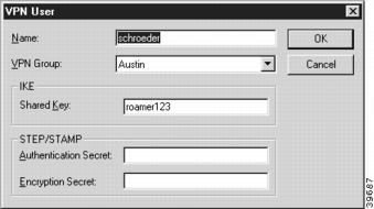
To add or modify user entries, you must access the VPN User dialog box by selecting the Add... or Modify... buttons in the VPN User Configuration dialog box (Figure 7-16).
This user database is global to the device.
Figure 7-16 VPN User Dialog Box
Name
This is the name of a user who will connect to the device using VPN client software.
VPN Group
The user whose name is entered in the first column will be given the privileges and session parameters described in the specified VPN Group Configuration.
Any number of user entries may specify the same VPN Group Configuration in the database, but the VPN Group Configuration itself may allow a limited number of simultaneous users to actually have open VPN sessions with a device.
IKE Shared Key
This is a shared alphanumeric secret between 1-255 characters long. It is used to generate session keys which are used to authenticate and/or encrypt each packet received or sent through the tunnel.
STEP/STAMP Authentication Secret
This is a shared alphanumeric long term secret between 1-255 characters long. It is used to generate a series of short term keys which will authenticate traffic from this user on a packet-by-packet basis.
The same secret must be entered into the VPN client in order for authentication to succeed.
STEP/STAMP Encryption Secret
This is a shared alphanumeric long term secret between 1-255 characters long. It is used to generate a series of short term keys which will be used to encrypt/decrypt information to and from the user.
The same secret must be entered into the VPN client in order for encryption and decryption to succeed.
IKE Policy
This section is used to set the Internet Security Association Key Management Protocol/Internet Key Exchange (ISAKMP/IKE) parameters. These settings control how the concentrator and client will identify and authenticate each other. This initial negotiation is referred to as Phase 1.
To access this dialog box (Figure 7-17), select Global/IKE Policy from the Device View.
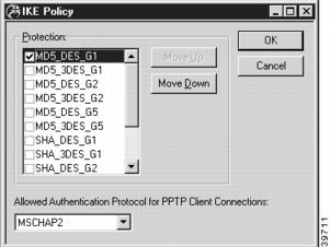
Figure 7-17 IKE Policy Global Dialog Box
The parameters set in this dialog box are global to the device and are not associated with a particular interface. These parameters specify a protection suite for the IKE negotiation between the concentrator and client. There are pieces to the IKE protection suite.
1.
2.
3.
Use the Move Up and Move Down buttons to arrange the priority of the protection suites.
Phase 2 IKE negotiation sets how the concentrator and client will handle individual tunnel sessions. Phase 2 IKE negotiation parameters are set in the VPN Group Configuration dialog box, in the IKE Configuration Tab.
Allowed Authentication Protocol for PPTP Client Connections
PPTP is currently not supported.
IPsec Gateway Dialog Box
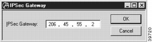
To access this dialog box (Figure 7-18), select Global/IPsecGateway in the Device View.
Figure 7-18 IPsec Gateway Configuration Dialog Box
IPsec Gateway
This is the IP address that will be used as the gateway to the Internet for IPsec traffic on a dual-Ethernet VPN 5000 concentrator. This is a required parameter only when the device is set to operate in parallel with your existing firewall (i.e. using both Ethernet ports) as the IPsec component of your security system.
The address should be entered as four decimal numbers separated by periods (e.g. 198.238.9.1).
This IP address must be on the same IP network as the IPsec interface, which is configured using the IP Connection dialog box (under Ethernet/IP Connection on the IPsec port of an VPN 5000 concentrator with two or more Ethernet interfaces).