Feedback Feedback
|
Table Of Contents
Cisco VPN 5008 Concentrator FRU Installation and Replacement Notes
AC Power Supply Specifications
Plugging In Cords and Turning On Power
DC Power Supply Specifications
Attaching the Connector Restraints
Installing Chassis Brackets and Handles
Moving the Chassis to a Table or Platform
Attaching the Rack-Mount Brackets and Shelf to the Rack
Moving the Chassis into the Rack
Obtaining Technical Assistance
Contacting TAC by Using the Cisco TAC Website
Cisco VPN 5008 Concentrator FRU Installation and Replacement Notes
This document provides information about installing and replacing field-replaceable units (FRUs) for the Cisco VPN 5008 concentrator. For more information on VPN 5008 concentrator hardware, see the Cisco VPN 5008 Concentrator Hardware Guide.
This document describes how to install and replace the following FRUs:
Warning
Only trained and qualified personnel should be allowed to install, replace, or service this equipment.
For a complete list of translated safety warnings, refer to the Regulatory Compliance and Safety Information for the Cisco VPN 5002 and 5008 Concentrators.
AC Power Supplies
Product Number: PWR-CVPN5008-AC+This section describes how to remove and replace the AC power supplies.
AC Power Supply Specifications
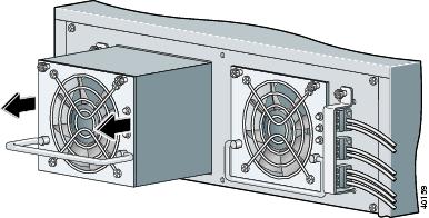
The 5008 chassis is shipped standard with dual redundant AC power supplies. Figure 1 and Table 1 describe the AC power supply components.
Figure 1 VPN 5008 AC Power Supplies
Replacing the AC Power Supply
Only trained, authorized personnel can replace a power supply. You need a medium Phillips screwdriver for the following procedure.
To replace the AC power supply on the VPN 5008 concentrator
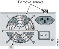
Step 1
Figure 2 Removing Power Supply Screws
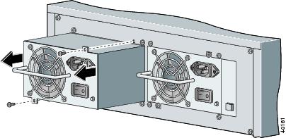
Step 2
Figure 3 Removing the Power Supply
Step 3
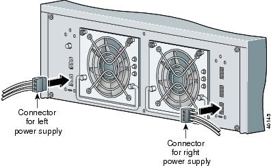
Plugging In Cords and Turning On Power
This section describes how to plug in the dual power supplies for the Cisco VPN 5008 concentrator.
To plug in and turn on dual chassis power supplies
Step 1
Step 2
Step 3
DC Power Supplies
Product Number: PWR-CVPN5008-DCThis section describes how to remove and replace the DC power supplies.
DC Power Supply Specifications
You can order optional dual redundant -48 VDC power supplies for connection to DC power. Figure 4 and Table 2 describe the DC power supply components for the VPN 5008 chassis.
Figure 4 VPN 5008 DC Power Supplies
Replacing the DC Power Supply
To replace the DC power supply on the VPN 5008 concentrator
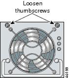
Step 1
Figure 5 Loosening Power Supply Thumbscrews
Step 2
Figure 6 Removing Power Supply
Step 3
Using the DC Power Supplies
This section describes how to wire the provided power connectors and alarm connectors on the VPN 5008 concentrator, and how to reset a power alarm for connection to DC power.
Wiring the Power Connector
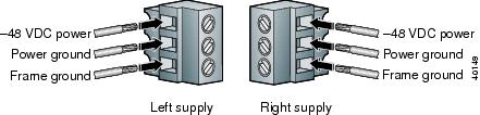
Each -48 VDC power supply includes a receptacle for a power connector. You must wire the provided connectors to the DC power source before plugging them into the power supplies (Figure 10).
For the DC power requirements, see the chassis back panel.
Figure 7 shows the wire locations for the DC power connector.
Note
Figure 7 DC Connector Wiring Diagram
To wire the power connectors
Step 1
Step 2
Step 3
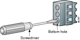
Figure 8 Loosening the Screw
Step 4
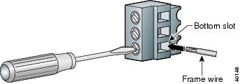
Figure 9 Attaching the Frame Ground Wire
Step 5
•
•
Step 6
Step 7
Figure 10 Plugging the Power Connectors into the Chassis
Step 8
Warning
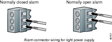
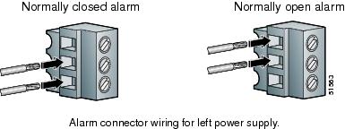
Wiring the Alarm Connectors
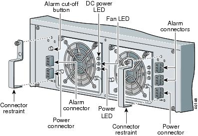
The VPN 5008 concentrator -48 VDC power supplies include three receptacles for alarm connectors: one each for critical, major, and minor alarms. In the event of a power interruption or system failure, the appropriate alarm activates.
The minor alarm activates if any power supply malfunctions. The major alarm activates if both power supplies malfunction. The critical alarm is currently unused.
The alarm relay switches support the following positions:
•
•
Figure 11 shows the wire locations for the alarm connectors on the right power supply. Figure 12 shows the wire locations for the alarm connectors on the left power supply.
Figure 11 Alarm Connector Wiring for the Right Power Supply
Figure 12 Alarm Connector Wiring for the Left Power Supply
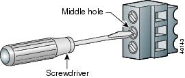
To wire the alarm connectors
Step 1
Step 2
Figure 13 Loosening the Screw
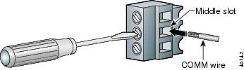
Step 3
Figure 14 Attaching the COMM Wire
Step 4
•
•
Step 5
Note
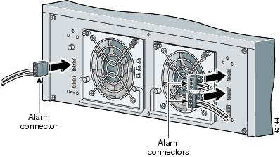
Figure 15 Plugging the Alarm Connectors into the Chassis
Resetting the Power Alarm
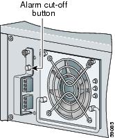
The power supply alarm activates in the event of a power interruption or malfunction. Use the alarm cut-off button on the left power supply (Figure 16) to deactivate the alarm and enable it again.
Figure 16 Alarm Cut-Off Button
If the system is still running despite alarm activation, it was probably disrupted by a temporary power failure. Press the alarm cut-off button to reactivate the alarm after an event.
If the system is not running, the cause of the alarm is either a continuing power failure or a catastrophic system failure. To determine the cause of the alarm, check the LEDs on the power supplies:
•
•
Attaching the Connector Restraints
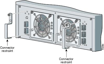
After the alarm connectors and power supply connectors are plugged in to the chassis, attach the connector restraints. The connector restraints prevent the alarm connectors and power supply connectors from being pulled out (Figure 17).
Have the following provided parts available:
•
•
To attach the connector restraints
Step 1
Step 2
For the left-side restraint, make sure the alarm cut-off button shows through the hole in the top of the restraint.
Step 3
Figure 17 Attaching the Connector Restraints
Rack-Mounting Kits
Product Number: ACS-CVPN5008-RMThis section describes how to install brackets and handles on the VPN 5008 chassis, the proper method for moving the chassis, and how to mount the chassis in a rack.
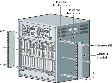
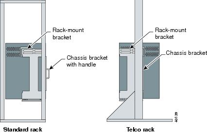
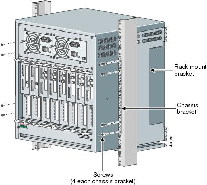
Installing Chassis Brackets and Handles
Install the chassis brackets and handles on the VPN 5008 chassis even if you do not plan to mount it in a rack. Do not install the handles for a telco rack, which does not provide enough finger room to use them.
You need a Phillips screwdriver to complete the following procedure.
Step 1
Use the front holes for a standard rack or table, and the middle holes for a telco rack (Figure 18).
Figure 18 Installing Chassis Brackets
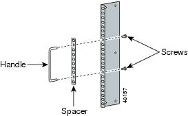
Step 2
Figure 19 Installing Handles for a Standard Rack or Table
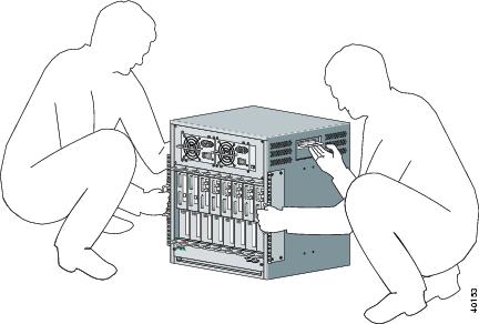
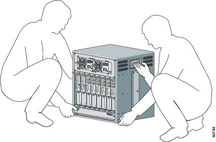
Moving the Chassis to a Table or Platform
After you attach the brackets, use two people to move the chassis to a table or platform by holding the front and side handles as shown in Figure 20.
Warning
Figure 20 Moving the Chassis onto a Table or Platform
Rack-Mounting the Chassis
You can mount the VPN 5008 chassis in a standard 19-inch equipment rack or in a telco rack. You must provide:
•
•
•
Rack Placement Considerations
Before you mount the chassis, consider the following rack guidelines:
•
•
•
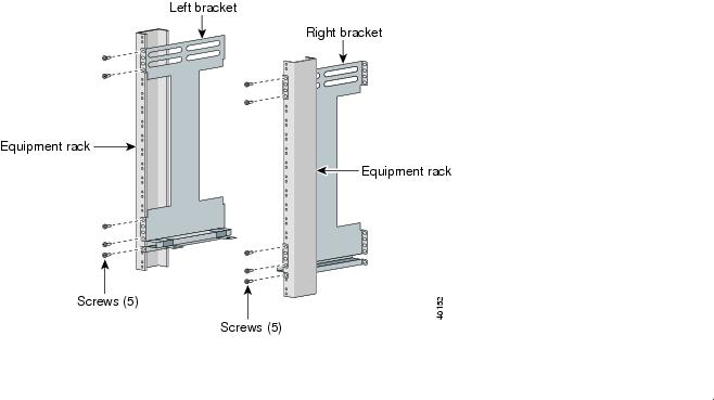
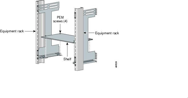
Attaching the Rack-Mount Brackets and Shelf to the Rack
This section describes how to attach the provided rack-mount brackets and shelf to the rack. The brackets and shelf maintain the proper alignment, but do not bear the weight of the chassis. The ledges at the bottom of the brackets bear the weight of the chassis until it is securely attached to the equipment rack.
To attach the brackets and shelf
Step 1
•
•
Figure 21 Fastening the Brackets to the Rack
Step 2
Step 3
Figure 22 Securing the Shelf
Step 4
Step 5
Moving the Chassis into the Rack
After you attach the brackets, complete the following steps to install the chassis in a rack.
Step 1
Warning
•
Figure 23 Moving the Chassis into a Standard Equipment Rack
•
Figure 24 Moving the Chassis into a Telco Rack
Step 2
Figure 25 Placing the Unit into a Rack
Step 3
Figure 26 Securing the Chassis to the Rack
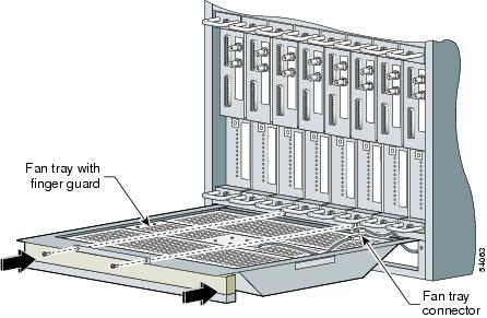
Fan Tray Assembly
Product Number: ACS-CVPN5008-FANThis section describes how to install and replace the fan tray assembly.
To replace the fan tray assembly
Step 1
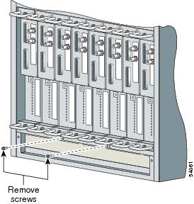
Figure 27 Removing the Bottom Panel
Step 2
Figure 28 Removing the Screws
Step 3
Step 4
Step 5
Figure 29 Fan Tray Assembly with Finger Guard
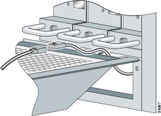
Make sure the connector wire is positioned in the slot at the back of the fan tray (Figure 30).
Figure 30 Positioning the Wire and Connector
Step 6
Step 7
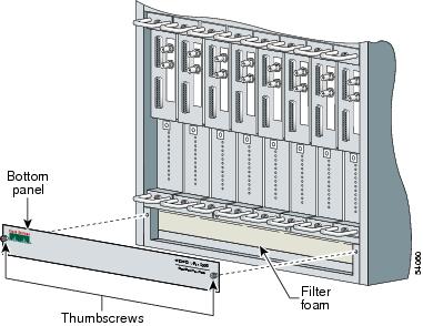
Replacing the Filter Foam
Product Number: ACS-CVPN5008-FILTERThis section describes how to replace the Cisco VPN 5008 chassis air filter.
Under normal operation, you do not need to replace the air filter. Replace the filter only if an excessive amount of dirt and dust collects over an extended period of time, or if a lit Over Temp LED appears on an ESP card. See the Cisco VPN 5002 and 5008 ESP Card Hardware Guide for more information about resolving a high-temperature condition.
Cisco Systems provides an extra filter with each unit to minimize the platform down time.
To change the filter, complete these steps:
Step 1
Figure 31 Replacing the Filter Foam
Step 2
Step 3
Step 4
If you want to reuse the old filter, wash it in warm, soapy water and allow to completely dry. If either of the supplied filters is worn out or cannot be thoroughly cleaned, you can order a replacement filter from Cisco Systems.
Obtaining Documentation
The following sections provide sources for obtaining documentation from Cisco Systems.
World Wide Web
You can access the most current Cisco documentation on the World Wide Web at the following sites:
•
•
•
Documentation CD-ROM
Cisco documentation and additional literature are available in a CD-ROM package, which ships with your product. The Documentation CD-ROM is updated monthly and may be more current than printed documentation. The CD-ROM package is available as a single unit or as an annual subscription.
Ordering Documentation
Cisco documentation is available in the following ways:
•
http://www.cisco.com/public/ordsum.html
•
http://www.cisco.com/go/subscription
•
Documentation Feedback
If you are reading Cisco product documentation on the World Wide Web, you can submit technical comments electronically. Click Feedback in the toolbar and select Documentation. After you complete the form, click Submit to send it to Cisco.
You can e-mail your comments to bug-doc@cisco.com.
To submit your comments by mail, use the response card behind the front cover of your document, or write to the following address:
Attn Document Resource Connection
Cisco Systems, Inc.
170 West Tasman Drive
San Jose, CA 95134-9883We appreciate your comments.
Obtaining Technical Assistance
Cisco provides Cisco.com as a starting point for all technical assistance. Customers and partners can obtain documentation, troubleshooting tips, and sample configurations from online tools. For Cisco.com registered users, additional troubleshooting tools are available from the TAC website.
Cisco.com
Cisco.com is the foundation of a suite of interactive, networked services that provides immediate, open access to Cisco information and resources at anytime, from anywhere in the world. This highly integrated Internet application is a powerful, easy-to-use tool for doing business with Cisco.
Cisco.com provides a broad range of features and services to help customers and partners streamline business processes and improve productivity. Through Cisco.com, you can find information about Cisco and our networking solutions, services, and programs. In addition, you can resolve technical issues with online technical support, download and test software packages, and order Cisco learning materials and merchandise. Valuable online skill assessment, training, and certification programs are also available.
Customers and partners can self-register on Cisco.com to obtain additional personalized information and services. Registered users can order products, check on the status of an order, access technical support, and view benefits specific to their relationships with Cisco.
To access Cisco.com, go to the following website:
http://www.cisco.com
Technical Assistance Center
The Cisco TAC website is available to all customers who need technical assistance with a Cisco product or technology that is under warranty or covered by a maintenance contract.
Contacting TAC by Using the Cisco TAC Website
If you have a priority level 3 (P3) or priority level 4 (P4) problem, contact TAC by going to the TAC website:
http://www.cisco.com/tac
P3 and P4 level problems are defined as follows:
•
•
In each of the above cases, use the Cisco TAC website to quickly find answers to your questions.
To register for Cisco.com, go to the following website:
http://www.cisco.com/register/
If you cannot resolve your technical issue by using the TAC online resources, Cisco.com registered users can open a case online by using the TAC Case Open tool at the following website:
http://www.cisco.com/tac/caseopen
Contacting TAC by Telephone
If you have a priority level 1 (P1) or priority level 2 (P2) problem, contact TAC by telephone and immediately open a case. To obtain a directory of toll-free numbers for your country, go to the following website:
http://www.cisco.com/warp/public/687/Directory/DirTAC.shtml
P1 and P2 level problems are defined as follows:
•
•