Feedback Feedback
|
Table Of Contents
Cisco VPN 5002 Concentrator FRU Installation and Replacement Notes
Mounting in a Standard Rack for Earthquake Safety
Attaching the Back Brackets to the Rack
Attaching the Front Brackets and Handles to the Chassis
Mounting the Chassis in the Rack
Attaching Brackets to the Chassis
Installing the Chassis on a Board
Obtaining Technical Assistance
Contacting TAC by Using the Cisco TAC Website
Cisco VPN 5002 Concentrator FRU Installation and Replacement Notes
This document provides information about installing and replacing field-replaceable units (FRUs) for the Cisco VPN 5002 concentrator. For more information on VPN 5002 concentrator hardware, see the Cisco VPN 5002 Concentrator Hardware Guide.
This document describes how to install the rack-mounting options that are available for the VPN 5002 concentrator, including:
•
Mounting in a Standard Rack for Earthquake Safety
•
Warning
For a complete list of translated safety warnings, refer to the Regulatory Compliance and Safety Information for the Cisco VPN 5002 and 5008 Concentrator.
Rack-Mounting Kit
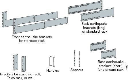
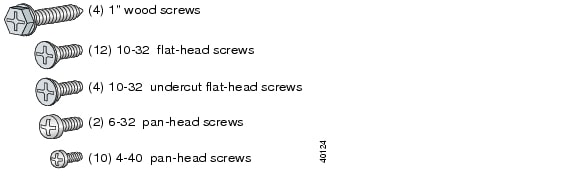
Product Number: ACS-CVPN5002-RMThe VPN 5002 rack mounting kit is shipped with the hardware shown in Figure 1 and the screws shown in Figure 2.
Figure 1 Mounting Bracket Hardware
Figure 2 Mounting Screws
Mounting in a Standard Rack
The VPN 5002 chassis requires 4 rack units of rack space. You must provide:
•
•
Complete the following steps to attach the provided brackets and handles to the chassis and to mount the chassis in the rack.
Step 1
Figure 3 Removing the Screws from the Chassis
Step 2
Figure 4 Attaching the Brackets to the Chassis
Step 3
Figure 5 Attaching the Handles to the Brackets
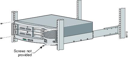
Step 4
Figure 6 Attaching the Chassis to the Rack
Mounting in a Standard Rack for Earthquake Safety
If the platform is located in an area prone to earthquakes, we strongly recommend that you use the earthquake brackets for mounting the device. The VPN 5002 chassis requires 4 rack units of rack space. You must provide:
•
•
Complete the following steps to attach the provided brackets and handles and to mount the chassis in the rack.
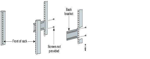
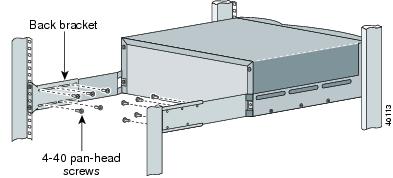
Attaching the Back Brackets to the Rack
To attach the back brackets to the rack
Step 1
Step 2
Figure 7 Installing the Back Brackets
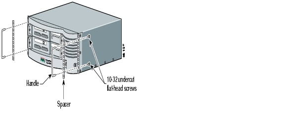
Attaching the Front Brackets and Handles to the Chassis
To attach the front brackets and handles to the chassis
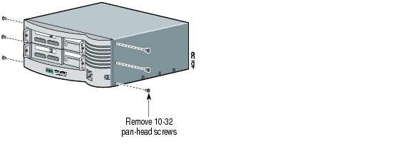
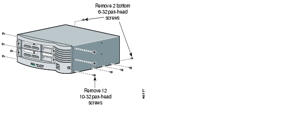
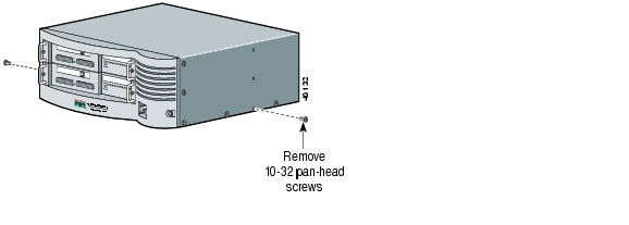
Step 1
Figure 8 Removing the Pan-Head Screws
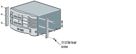
Step 2
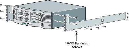
Figure 9 Attaching the Front Brackets
Step 3
Figure 10 Attaching the Bracket Tabs
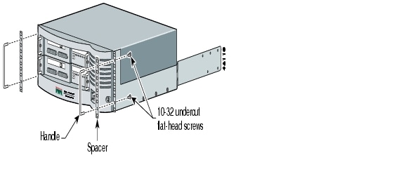
Step 4
Figure 11 Attaching the Handles to the Brackets
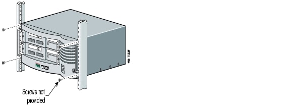
Mounting the Chassis in the Rack
To mount the chassis in the rack
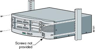
Step 1
Step 2
Figure 12 Mounting the Chassis in the Rack
Step 3
Figure 13 Joining the Front and Back Brackets
Mounting in a Telco Rack
The chassis requires 4 rack units of rack space. You must provide:
•
•
Complete the following steps to attach the provided brackets and to mount the chassis in the rack.
Step 1
Figure 14 Removing the Pan-Head Screws
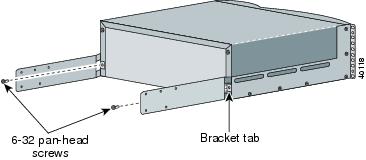
Step 2
Figure 15 Attaching the Brackets to the Chassis
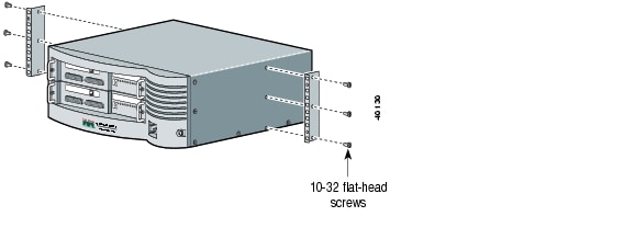
Step 3
Figure 16 Mounting the Brackets to the Rack
Wall-Mounting the Chassis
To mount the chassis sideways and flat against a wall, you must provide:
•
•
•
Complete the following steps to attach the provided brackets and to mount the chassis to the wall.
Attaching Brackets to the Chassis
To attach the brackets to the chassis
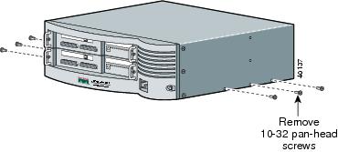
Step 1
Figure 17 Removing the Screws from the Chassis
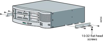
Step 2
Figure 18 Attaching Brackets to the Chassis
Installing the Chassis on a Board
To install the chassis on a board
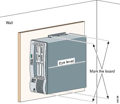
Step 1
To determine the screw locations, refer to Figure 19, which shows the chassis positioned sideways and flat against the wall at eye level.
Figure 19 Determining Screw Locations
Step 2
Step 3
a.
b.
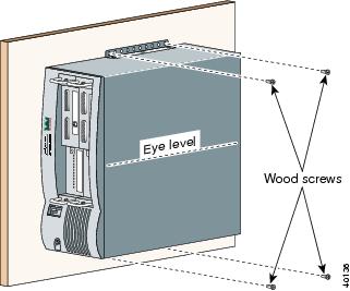
Step 4
Figure 20 Attaching the Chassis to the Wall
Obtaining Documentation
The following sections provide sources for obtaining documentation from Cisco Systems.
World Wide Web
You can access the most current Cisco documentation on the World Wide Web at the following sites:
•
•
•
Documentation CD-ROM
Cisco documentation and additional literature are available in a CD-ROM package, which ships with your product. The Documentation CD-ROM is updated monthly and may be more current than printed documentation. The CD-ROM package is available as a single unit or as an annual subscription.
Ordering Documentation
Cisco documentation is available in the following ways:
•
http://www.cisco.com/public/ordsum.html
•
http://www.cisco.com/go/subscription
•
Documentation Feedback
If you are reading Cisco product documentation on the World Wide Web, you can submit technical comments electronically. Click Feedback in the toolbar and select Documentation. After you complete the form, click Submit to send it to Cisco.
You can e-mail your comments to bug-doc@cisco.com.
To submit your comments by mail, for your convenience many documents contain a response card behind the front cover. Otherwise, you can mail your comments to the following address:
Cisco Systems, Inc.
Document Resource Connection
170 West Tasman Drive
San Jose, CA 95134-9883We appreciate your comments.
Obtaining Technical Assistance
Cisco provides Cisco.com as a starting point for all technical assistance. Customers and partners can obtain documentation, troubleshooting tips, and sample configurations from online tools. For Cisco.com registered users, additional troubleshooting tools are available from the TAC website.
Cisco.com
Cisco.com is the foundation of a suite of interactive, networked services that provides immediate, open access to Cisco information and resources at any time, from anywhere in the world. This highly integrated Internet application is a powerful, easy-to-use tool for doing business with Cisco.
Cisco.com provides a broad range of features and services to help customers and partners streamline business processes and improve productivity. Through Cisco.com, you can find information about Cisco and our networking solutions, services, and programs. In addition, you can resolve technical issues with online technical support, download and test software packages, and order Cisco learning materials and merchandise. Valuable online skill assessment, training, and certification programs are also available.
Customers and partners can self-register on Cisco.com to obtain additional personalized information and services. Registered users can order products, check on the status of an order, access technical support, and view benefits specific to their relationships with Cisco.
To access Cisco.com, go to the following website:
http://www.cisco.com
Technical Assistance Center
The Cisco TAC website is available to all customers who need technical assistance with a Cisco product or technology that is under warranty or covered by a maintenance contract.
Contacting TAC by Using the Cisco TAC Website
If you have a priority level 3 (P3) or priority level 4 (P4) problem, contact TAC by going to the TAC website:
http://www.cisco.com/tac
P3 and P4 level problems are defined as follows:
•
•
In each of the above cases, use the Cisco TAC website to quickly find answers to your questions.
To register for Cisco.com, go to the following website:
http://www.cisco.com/register/
If you cannot resolve your technical issue by using the TAC online resources, Cisco.com registered users can open a case online by using the TAC Case Open tool at the following website:
http://www.cisco.com/tac/caseopen
Contacting TAC by Telephone
If you have a priority level 1(P1) or priority level 2 (P2) problem, contact TAC by telephone and immediately open a case. To obtain a directory of toll-free numbers for your country, go to the following website:
http://www.cisco.com/warp/public/687/Directory/DirTAC.shtml
P1 and P2 level problems are defined as follows:
•
•