Table Of Contents
Configuration Examples
Basic Two Interface Configuration without NAT
Basic Two Interface Configuration with NAT
Two Interface Multiple Server Configuration
Three Interfaces without NAT
Three Interfaces with NAT
Four Interfaces with NAT
Higher Security Level to Lower Security Level Access
Lower Security Level to Higher Security Level Access
Configuration Examples
Before using this chapter, be sure that you have planned your site's security policy, as described in Chapter 1, "," and configured the PIX Firewall, as described in Chapter 2, "."
This chapter provides network diagrams and the configuration instructions to create them. Further information about the commands in the configurations can be found in Chapter 5, "."
If you are starting a configuration, you may want to use the forms provided in Appendix A, "" to help you plan a configuration.
Acronyms in the text are defined in Appendix B, "."
The following topics are discussed:
• Basic Two Interface Configuration without NAT
•Basic Two Interface Configuration with NAT
•Two Interface Multiple Server Configuration
•Three Interfaces without NAT
•Three Interfaces with NAT
•Four Interfaces with NAT
Basic Two Interface Configuration without NAT
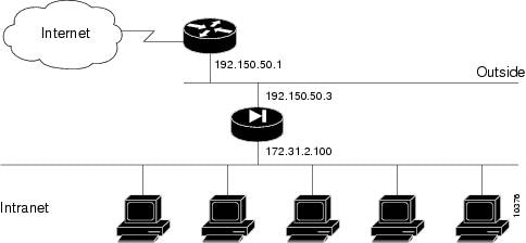
When you first add a PIX Firewall to an existing network, it is easiest to implement its use if you do not have to renumber all the inside and outside IP addresses. The configuration in illustrates this scenario. Syslog is enabled to facilitate troubleshooting. All inside hosts can start connections. All external hosts are blocked from initiating connections or sessions on inside hosts. If you use Inter-NIC registered IP addresses, only use those addresses that you own.
Figure 4-1 Two Interface Configuration without NAT
lists the configuration.
Table 4-1 Two Interface Configuration without NAT
Configuration
|
Description
|
nameif ethernet0 outside security0
nameif ethernet1 inside security100
|
PIX Firewall provides nameif statements for the inside and outside interfaces and the interface statements for both interfaces in the default configuration (default configuration statements are shown in bold and italics).
|
ip address outside 192.150.50.3 255.255.255.0
ip address inside 172.31.2.100 255.0.0.0
|
Identify the IP addresses for both interfaces.
|
|
Specifies the host name for the PIX Firewall. This name appears in the command line prompt.
|
|
Sets the ARP timeout to 14,400 seconds (four hours). Entries are kept in the ARP table for four hours before they are flushed. Four hours is the standard default value for ARP timeouts.
|
|
Disables failover access.
|
|
Enables use of text strings instead of IP addresses. This makes your configuration files more readable.
|
|
Enables paging so that if when 24 lines of information display, PIX Firewall pauses the listing and prompts you to continue.
|
logging buffered debugging
|
Enables syslog messages, which provide diagnostic information and status for the PIX Firewall. PIX Firewall makes it easy to view syslog messages with the show logging command.
|
|
Lets inside IP addresses be recognized on the outside network and lets inside users start outbound connections.
|
|
Sets RIP listening attributes. The first command causes the PIX Firewall to broadcast a default route on the inside interface. Broadcasting a default route sends network traffic to the PIX Firewall if your internal network is running RIP. The next command disables passive RIP listening on the inside. The next command disables broadcasting a default route on the outside. This is desirable when the network is attached to the Internet, but not when on an intranet. The last command enables passive RIP listening on the outside.
|
route outside 0.0.0.0 0.0.0.0 192.150.50.1 1
|
Sets the outside default route to the router attached to the Internet.
|
timeout xlate 3:00:00 conn 1:00:00 udp 0:02:00
timeout rpc 0:10:00 h323 0:05:00
timeout uauth 0:05:00 absolute
|
Default values for the maximum duration that PIX Firewall resources can remain idle until being freed. Additional users cannot make connections until a connection license (resource) is freed either by a user dropping a connection or by an xlate and conn timer time out. You can set the xlate and conn timers from 24 hours to 1 hour, depending on your site requirements.
|
snmp-server community public
|
Specifies that SNMP information may be accessed by internal hosts that know the community string, but PIX Firewall does not send trap information to any host.
|
|
Sets the maximum transmission unit value for Ethernet access.
|
Basic Two Interface Configuration with NAT
In , the PIX Firewall has two interfaces. In this configuration, there is no user authentication, no authorization, and no syslog or SNMP logging of troubleshooting messages. All inside users can start outbound connections and all connections from the outside are dropped. A configuration such as this is a good example of the basic commands used to create a secured network.
Figure 4-2
Basic Two Interface Configuration
lists the configuration.
Table 4-2 Basic Two Interface Configuration
Configuration
|
Description
|
nameif ethernet0 outside security0
nameif ethernet1 inside security100
|
PIX Firewall provides nameif statements for the inside and outside interfaces and the interface statements for both interfaces in the default configuration (default configuration statements are shown in bold and italics).
|
ip address outside 192.150.50.3 255.255.255.0
ip address inside 10.0.0.3 255.0.0.0
|
Identify the IP addresses for both interfaces.
|
|
Set the ARP timeout to 14,400 seconds (four hours). Entries are kept in the ARP table for four hours before they are flushed.
|
|
Permit all inside users to start outbound connections using the translated IP addresses from the global pool.
|
global (outside) 1 192.150.50.76-192.150.50.85
global (outside) 1 192.150.50.75
|
Create a pool of global addresses that translated addresses use when they exit the firewall from the protected networks to the unprotected networks. The global is associated with a nat statement by the nat_ID, which in this example is 1. Because there are only 9 IP addresses in the pool, a PAT (Port Address Translation) global is added to handle overflow. Because PIX Firewall reads through the pool of global addresses from the highest number to the lowest, the PAT is placed at the start of the range.
|
|
PIX Firewall does use RIP information for its forwarding decisions, but these commands can be useful for broadcasting a default route—if your network uses the RIP protocol. However, most do not. In most cases, you can ignore these statements.
|
route outside 0.0.0.0 0.0.0.0 192.150.50.1 1
|
Set the outside default route to the router attached to the Internet.
|
timeout xlate 3:00:00 conn 1:00:00 udp 0:02:00
timeout rpc 0:10:00 h323 0:05:00
timeout uauth 0:05:00 absolute
|
Default values for the maximum duration that PIX Firewall resources can remain idle until being freed. Additional users cannot make connections until a connection license (resource) is freed either by a user dropping a connection or by an xlate and conn timer time out. You can set the xlate and conn timers from 24 hours to 1 hour, depending on your site requirements.
|
conduit permit icmp any any
|
Allows inbound and outbound pings.
|
snmp-server community public
|
Specifies that SNMP information may be accessed by internal hosts that know the community string, but PIX Firewall does not send trap information to any host.
|
telnet 10.0.0.100 255.255.255.255
|
Specifies that host 10.0.0.100 is permitted to access the PIX Firewall console via Telnet and that 15 minutes are allowed before the idle timer runs out and the session is logged off.
|
|
Sets the maximum transmission unit value for Ethernet access.
|
Two Interface Multiple Server Configuration
The configuration in provides an overview of how the various commands are used to create a configuration.
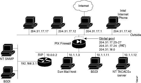
This configuration shows the use of PAT (Port Address Translation), denying Java applets, using the AAA commands, creating a mail server, permitting NFS, initializing SNMP, and setting console access with Telnet.
Figure 4-3 Configuring Multiple Features
lists the configuration.
Table 4-3 Multiple Server Configuration
Configuration
|
Description
|
nameif ethernet0 outside security0
nameif ethernet1 inside security100
|
PIX Firewall provides nameif statements for the inside and outside interfaces and the interface statements for both interfaces in the default configuration (default configuration statements are shown in bold and italics).
|
ip address inside 10.1.1.1 255.0.0.0
ip address outside 204.31.17.10 255.255.255.0
|
Identify the IP addresses for both interfaces.
|
|
The logging host command specifies which host runs a syslog server. This command also causes the PIX Firewall to start sending syslog messages to that host. The logging trap command sets syslog to send all possible messages to the syslog host. The no logging console command disables displaying messages to the console.
|
|
Set an ARP timeout to 600 seconds (10 minutes). Use this arp timeout command when you set up a network and change inside and outside host addresses often.
|
nat (inside) 1 10.0.0.0 255.0.0.0
nat (inside) 2 192.168.3.0 255.255.255.0
|
Permit all inside users to start outbound connections using the translated IP addresses from the global pool.
|
global (outside) 1 204.31.17.25-204.31.17.27
global (outside) 1 204.31.17.24
global (outside) 2 192.159.1.1-192.159.1.254
|
Create two pools of global addresses to let the nat statements use the address pools for translating internal IP addresses to external addresses. Each pool is designated by the number from the nat command, in this case, 1 and 2. Pool 1 consists of four IP addresses, the first three in the range from 204.31.17.25 to 204.31.17.27, and a PAT address, 204.31.17.28. The PAT address lets up to 64,000 hosts be translated through this single address. Pool 2 consists of 254 hosts from 192.159.1.1 to 192.159.1.254.
|
conduit permit icmp any any
|
Allow inbound and outbound pings.
|
outbound 10 deny 192.168.3.3 255.255.255.255 1720
outbound 10 permit 192.168.3.3 255.255.255.255 80
outbound 10 deny 192.168.3.3 255.255.255.255 java
outbound 10 permit 10.1.1.11 255.255.255.255 80
|
Create access lists to determine which hosts can access services. The first outbound statement denies host 192.168.3.3 from accessing H.323 (port 1720) services such as MS NetMeeting or InternetPhone. The next statement denies all hosts from accessing the Web (port 80). The next two statements permits host 192.168.3.3 to use the Web, but denies its users from downloading Java applets. The last outbound statement permits host 10.1.1.11 access to the Web (at port 80) and to download Java applets. This permit statement outweighs the previous deny regardless of the order in which the statements are entered into the configuration.
|
apply (inside) 10 outgoing_src
|
Specify that the outbound group regulates the activities of inside hosts starting outbound connections.
|
|
|
The first command disables RIP listening on the outside interface. The second command disables broadcasting a default route on the outside.
The third command enables RIP listening on the inside and the last command causes PIX Firewall to broadcast a default route on the inside interface.
|
route outside 0 0 204.31.17.1 1
|
Set the default route on the outside network to be 204.31.17.1. This is the IP address of the host connecting to the Internet.
|
tacacs-server host 10.1.1.12 1q2w3e
aaa authentication any inside 192.168.3.0
255.255.255.0 0 0 tacacs+
aaa authorization any inside 192.168.3.0
|
The tacacs-server command specifies the IP address of the TACACS+ authentication server. The aaa authentication statement specifies that users on network 192.168.3.0 starting FTP, HTTP, and Web connections from the inside interface be prompted for their usernames and passwords before being permitted to access these servers on other interfaces. The aaa authorization statement lets the users on 192.168.3.0 access FTP, HTTP, or Telnet, and any TCP connections to anywhere as authorized by the AAA server. Even though it appears that the aaa commands let the PIX Firewall set security policy, the authentication server actually does the work to decide which users are authenticated and what services they can access when authentication is permitted.
|
static (inside, outside) 204.31.19.0 192.168.3.0
netmask 255.255.255.0
conduit permit tcp 204.31.19.0 255.255.255.0

eq h323 any
|
The static statement creates a net static. A net static is a static statement for a Class IP address, in this case for IP addresses 204.31.19.1 through 204.31.19.254. The static command shows the use of the connection limit and the embryonic limit arguments. The maximum number of connections limits the number of connections a host can use. This command permits access to only 10 users and up to 30 SYNs (embryonic connections). Note that the static command's maximum connections option applies to both inbound and outbound connections.
The conduit statement lets users on the Internet send InternetPhone (port h323) requests to users on 192.168.3.x while addressing them as 204.31.19.x.
|
static (inside, outside) 204.31.17.29 10.1.1.11
conduit permit tcp host 204.31.17.29 eq 80 any
|
The static statement with the conduit statement establishes an externally visible IP address for Web access (port 80 in the conduit statement).
|
conduit permit udp host 204.31.17.29 eq rpc

host 204.31.17.17
|
Refine the accessibility of the static command by permitting Sun RPC over the UDP portmapper on port 111. Refer to the UNIX /etc/rpc file and the UNIX rpc(3N) command page for more information. Once you create a conduit for RPC, you can use the following command from outside host 204.31.17.17 to track down the activity of a PCNFSD on RPC 150001:
rpcinfo -u 204.31.17.29 150001
Another use of RPC is with the following command to see the exports of 204.31.17.29 if you want to allow NFS mounting from outside in.
showmount -e 204.31.17.29
Many protocols based on RPC, as well as NFS, are insecure and should be used with caution. Review your security policies carefully before permitting access to RPC.
|
conduit permit udp host 204.31.17.29 eq 2049

host 204.31.17.17
|
Permit NFS access, which occurs at port 2049 and provides access between the outside and inside, such that 204.31.17.17 can mount 10.1.1.11.
|
static (inside, outside) 204.31.17.30 10.1.1.3

netmask 255.255.255.255 10 10
conduit permit tcp host 204.31.17.30 eq smtp any
|
Identify access to the 10.1.1.3 mail server through global address 204.31.17.30. The conduit permits any outside host access to the static via SMTP (port 25). By default, PIX Firewall restricts all access to mail servers to RFC 821 section 4.5.1 commands of DATA, HELO, MAIL, NOOP, QUIT, RCPT, and RSET. This occurs via the Mail Guard service which is set with the following default configuration command:
fixup protocol smtp 25
Another aspect of providing access to a mail server is setting being sure that you have a DNS MX record for the static's global address, which outside users access when sending mail to your site.
|
conduit permit tcp host 204.31.17.30 eq 113 any
|
Create access to port 113, the IDENT protocol. If the mail server has to talk to many mail servers on the outside which connect back with the now obsolete and highly criticized IDENT protocol, use this conduit to speed up mail transmission.
|
snmp-server host 192.168.3.2
snmp-server location building 42
snmp-server contact polly hedra
snmp-server community ohwhatakeyisthee
|
These commands specify that host 192.168.3.2 can receive SNMP events, which the PIX Firewall sends via syslog. The location and contact commands identify where the host is and who administers it. The community command describes the password in use at the SNMP server for verifying network access with the server.
|
telnet 10.1.1.11 255.255.255.255
telnet 192.168.3.0 255.255.255.0
|
These commands permit host access to the PIX Firewall console. The first telnet command permits a single host, 10.1.1.11 to access the PIX Firewall console with Telnet. The 255 value in the last octet of the netmask means that only the specified host can access the console.
The second telnet command permits PIX Firewall console access from all hosts on the 192.168.3.0 network. The 0 value in the last octet of the netmask permits all hosts in that network access. However, Telnet only permits 16 hosts simultaneous access to the PIX Firewall console over Telnet.
|
Three Interfaces without NAT
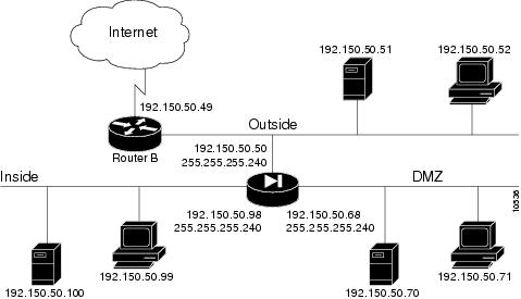
In , the PIX Firewall has three interfaces. No address translation is performed between the interfaces.
Figure 4-4
Three Interface Configuration
The network has the following IP addresses and network masks:
•Outside network interface address: 192.150.50.50, network mask: 255.255.255.240
•Inside network interface address: 192.150.50.98, network mask: 255.255.255.240
•DMZ network interface address: 192.150.50.68, network mask: 255.255.255.240
lists the configuration.
Table 4-4 Three Interface Configuration
Configuration
|
Description
|
nameif ethernet0 outside security0
nameif ethernet1 inside security100
nameif ethernet2 dmz security50
|
PIX Firewall provides nameif statements for the inside and outside interfaces and the interface statements for all three interfaces in the default configuration (default configuration statements are shown in bold and italics).
You need to add a nameif statement for the perimeter interface.
|
ip address outside 192.150.50.50 255.255.255.240
ip address inside 192.150.50.98 255.255.255.240
ip address dmz 192.150.50.68 255.255.255.240
|
Identify the IP addresses for each of the three interfaces.
|
|
Specifies the host name for the PIX Firewall. This name appears in the command line prompt.
|
|
Sets the ARP timeout to 14,400 seconds (four hours). Entries are kept in the ARP table for four hours before they are flushed. Four hours is the standard default value for ARP timeouts.
|
|
Disables failover access.
|
|
Enables use of text strings instead of IP addresses. This makes your configuration files more readable.
|
|
Enables paging so that if when 24 lines of information display, PIX Firewall pauses the listing and prompts you to continue.
|
logging buffered debugging
|
Enable syslog messages, which provide diagnostic information and status for the PIX Firewall. You can view the messages with the show logging command and clear the message buffer with the clear logging command.
|
|
Sets RIP listening attributes. The two rip interface passive commands cause the PIX Firewall to listen to RIP broadcasts on each interface. The no rip interface default commands causes PIX Firewall to not broadcast a default route on either interface.
|
route outside 0.0.0.0 0.0.0.0 192.150.50.1 1
|
Sets the outside default route to the router attached to the Internet.
|
timeout xlate 3:00:00 conn 1:00:00 udp 0:02:00
timeout rpc 0:10:00 h323 0:05:00
timeout uauth 0:05:00 absolute
|
Default values for the maximum duration that PIX Firewall resources can remain idle until being freed. To improve system performance, you can set the xlate and conn timers from 24 hours to 1 hour.
|
snmp-server community public
|
Specifies that SNMP information may be accessed by internal hosts that know the community string, but PIX Firewall does not send trap information to any host.
|
|
Sets the maximum transmission unit value for Ethernet access.
|
|
Disables NAT (Network Address Translation).
|
static (dmz,outside) 192.150.50.70 192.150.50.70
conduit permit tcp host 192.150.50.70 any
|
Maps access to the 192.150.50.70 host on the dmz interface. The conduit command lets any outside user access the host on any port.
|
Three Interfaces with NAT
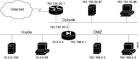
In , the PIX Firewall has three interfaces and these attributes:
•Address translation is performed between the interfaces.
•A web server on the dmz interface is publicly accessible. The name command maps its host address to the name "webserver."
•The inside network has illegal addresses (10.0.0.0), the dmz interface has RFC 1918 addresses (192.168.0.0), and the outside network has legal, registered addresses (192.150.50.0).
•TCP and UDP connections from the inside are allowed to go out on the DMZ and outside.
•An inside host has been given Telnet access to the PIX Firewall console.
Figure 4-5
Three Interfaces with NAT
The network has the following IP addresses and network masks:
•Outside network interface address: 192.150.50.3, network mask: 255.255.255.0
•Allowable global and static addresses on the outside network: 192.150.50.74-192.150.50.85
•Inside network interface address: 10.0.0.3, network mask: 255.0.0.0
•DMZ network interface address: 192.168.0.1, network mask: 255.255.255.0
Table 4-5 Three Interfaces with NAT
Configuration
|
Description
|
nameif ethernet0 outside security0
nameif ethernet1 inside security100
nameif ethernet2 dmz security50
|
PIX Firewall provides nameif statements for the inside and outside interfaces and the interface statements for all three interfaces in the default configuration (default configuration statements are shown in bold and italics).
You need to add a nameif statement for the perimeter interface.
|
ip address outside 192.150.50.3 255.255.255.0
ip address inside 10.0.0.3 255.0.0.0
ip address dmz 192.168.0.1 255.255.255.0
|
Identify the IP addresses for each of the three interfaces.
|
|
Specify the host name for the PIX Firewall. This name appears in the command line prompt.
|
|
Set the ARP timeout to 14,400 seconds (four hours). Entries are kept in the ARP table for four hours before they are flushed. Four hours is the standard default value for ARP timeouts.
|
|
Disable failover access.
|
|
Enable use of text strings instead of IP addresses. This makes your configuration files more readable.
|
|
Enable paging so that if after 24 lines of information display, PIX Firewall pauses the listing and prompts you to continue.
|
logging buffered debugging
|
Enable syslog messages, which provide diagnostic information and status for the PIX Firewall. You can view the messages with the show logging command and clear the message buffer with the clear logging command.
|
|
Disable RIP attributes.
|
route outside 0.0.0.0 0.0.0.0 192.150.50.1 1
|
Set the outside default route to the router attached to the Internet.
|
conduit permit icmp any any
|
Allow inbound and outbound pings.
|
timeout xlate 3:00:00 conn 1:00:00 udp 0:02:00
timeout rpc 0:10:00 h323 0:05:00
timeout uauth 0:05:00 absolute
|
Default values for the maximum duration that PIX Firewall resources can remain idle until being freed.
|
snmp-server community public
|
Specify that SNMP information may be accessed by internal hosts that know the community string, but PIX Firewall does not send trap information to any host.
|
|
Set the maximum transmission unit value for Ethernet access.
|
telnet 10.0.0.100 255.255.255.255
|
Give Telnet access to PIX Firewall console to inside host. Use the version 4.2(3) timeout feature to set the maximum time a Telnet session can be idle before PIX Firewall closes the connection to 15 minutes. The default is 5 minutes.
|
global (outside) 1 192.150.50.75-192.150.50.85
global (outside) 1 192.150.50.74
global (dmz) 1 192.168.0.10-192.168.0.20
|
Create a pool of global addresses for the outside and dmz interfaces. Because there are only 10 outside IP addresses, add a PAT global to the end of the range to handle overflow. Because PIX Firewall reads through the pool of global addresses from the highest number to the lowest, the PAT is placed at the start of the range. The global (dmz) command gives inside users access to the web server on the dmz interface.
|
nat (inside) 1 10.0.0.0 255.0.0.0
nat (dmz) 1 192.168.0.0 255.255.255.0
|
Let inside users start connections on the dmz and outside interfaces, and let dmz users start connections on the outside interface.
|
name 192.168.0.2 webserver
|
Give the IP address of the web server a label.
|
static (dmz,outside) 192.150.50.90 webserver
conduit permit tcp host 192.150.50.90 eq 80 any
|
Let any user on the outside interface access the web server on the dmz interface.
|
lists the configuration.
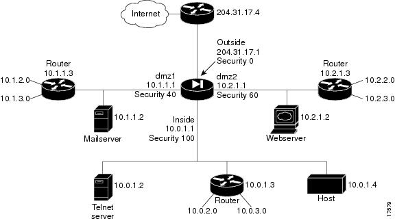
Four Interfaces with NAT
In , the PIX Firewall has four interfaces. In this configuration, there is no user authentication and no authorization. NAT (Network Address Translation) is in effect to translate addresses. In this example, users on all interfaces have access to all the servers and hosts on the inside, dmz1, and dmz2 interfaces can start connections.
Figure 4-6
Four Interfaces With NAT
Configuring PIX Firewall for four interfaces requires more attention to detail than other configurations. The most important guidelines to remember are:
•Higher to lower—To let users on a higher security level interface access hosts on a lower security interface, use the nat and global commands; for example, to let users on the inside interface access the web server on the dmz2 interface. As seen in , the inside interface has a security level of 100 and the dmz2 interface has a security level of 60.
The nat command lets users access all hosts on all lower security level interfaces. The global command identifies the interface through which the nat access is permitted.
•Lower to higher—To let users on a lower security level interface access hosts on a higher security interface, use the static and conduit commands; for example, to let users on the dmz1 interface access the Telnet server on the inside interface. As seen in , the dmz1 interface has a security level of 40 and the inside interface has a security level of 100.
The static command lets users access specifically identified hosts on a single interface. The conduit command identifies the port or ports through which access is permitted.
The sections that follow provide more information on these guidelines.
Higher Security Level to Lower Security Level Access
To let users on each higher security level interface access servers on each lower security level interface, follow these steps:
Step 1 Letting higher security level interface users access a lower security level interface has two components: you use the nat command to specify from where users start connections, and you use the global command to specify to where access is permitted. You associate the nat and global commands together with the NAT ID, which in this example configuration is 1. The nat command lets users start connections from the specified interface to all lower security interfaces, the global command permits access to translated connections from any higher security level interface.
To let users from the inside interface start connections, use:
Step 2 To let users on the dmz2 interface start connections, use:
Step 3 To let users on the dmz1 interface start connections, use:
Step 4 To permit access to the dmz2 interface for translated connections, use:
global (dmz2) 1 10.2.1.10-10.2.1.254
Step 5 To permit access to the dmz1 interface for translated connections, use:
global (dmz1) 1 10.1.1.10-10.1.1.254
Step 6 To permit access to the outside interface for translated connections, use:
global (outside) 1 204.31.17.10-204.31.17.254
o
Lower Security Level to Higher Security Level Access
To let users on a lower security level interface access a server on a higher security level interface, use the static and conduit commands. The first IP address in the static command is the address users on the lower security level interface use when they want to access the server on the higher security level interface. The second IP address is the actual address of the server.
When you enter the static statement in your configuration, always specify the security level of the interfaces as (higher,lower) and the IP addresses as lower and higher; for example:
static (inside,dmz1) 10.1.1.7 10.0.1.2
When users on the dmz1 interface access the Telnet server, they use IP address 10.1.1.7.
To let users on each lower security level interface access servers on each higher security level interface, follow these steps:
Step 1 To let users on the outside interface access the mail server on the dmz1 interface, use:
static (dmz1,outside) 204.31.17.5 10.1.1.2
conduit permit tcp host 204.31.17.5 eq smtp any
Step 2 To let users on the outside interface access the web server on the dmz2 interface, use:
static (dmz2,outside) 204.31.17.6 10.2.1.2
conduit permit tcp host 204.31.17.6 eq www any
Step 3 To let users on the outside interface access the Telnet server on the inside interface, use:
static (inside,outside) 204.31.17.7 10.0.1.2
conduit permit tcp host 204.31.17.7 eq telnet any
Step 4 To let users on the dmz1 interface access the web server on the dmz interface, use:
static (dmz2,dmz1) 10.1.1.6 10.2.1.2
conduit permit tcp host 10.1.1.6 eq www any
Step 5 To let users on the dmz1 interface access the Telnet server on the inside interface, use:
static (inside,dmz1) 10.1.1.7 10.0.1.2
conduit permit tcp host 10.1.1.7 eq telnet any
Step 6 To let users on the dmz2 interface access the Telnet server on the inside interface, use:
static (inside,dmz2) 10.2.1.7 10.0.1.2
conduit permit tcp host 10.2.1.7 eq telnet any
All configuration statements are explained in greater detail in .
Once you sketch out your network and map these steps to your IP addresses and servers, the four interface configuration can become a simpler task.
The addresses used in this configuration are as follows:
•The outside interface: 204.31.17.1 with static global addresses of 204.31.17.5 for the mail server on dmz1, 204.31.17.6 for the web server on dmz2, and 204.31.17.7 for the Telnet server on the inside. In addition, a pool of global addresses is defined as 204.31.17.10-204.31.17.254. A PAT (Port Address Translation) global is provided at 204.31.17.9.
•The dmz1 interface: 10.1.1.1 with static global addresses of 10.1.1.6 for the web server on dmz2 and 10.1.1.7 for the Telnet server on the inside. A pool of global addresses is defined as 10.1.1.10-10.1.1.254.
•The dmz2 interface: 10.2.1.1 with a static global address of 10.2.1.7 for the Telnet server on the inside and a pool of global addresses of 10.2.1.10-10.2.1.254.
•The inside interface: 10.0.1.1.
In addition static route statements are required to permit access to the networks that connect to the routers. A static route statement directs traffic meant for a network to the router on the interface. The format for a static route is shown in the following example:
route inside 10.0.2.0 255.0.0.0 10.0.1.3 1
This statement instructs the PIX Firewall that when a packet needs to be sent to an address in the 10.0.2.0 network, send it to the router on the inside interface at 10.0.1.3.
Because there are routers on the inside, dmz2, and dmz1 interfaces with two networks connecting to each, six static route statements are required—two for each interface.
lists a four interface configuration:
Table 4-6 Four Interface Configuration
Configuration
|
Description
|
nameif ethernet0 outside security0
nameif ethernet1 inside security100
nameif ethernet2 dmz1 security40
nameif ethernet3 dmz2 security60
|
PIX Firewall provides nameif statements for the inside and outside interfaces and the interface statements for all four interfaces in the default configuration (default configuration statements are shown in bold and italics).
You need to create two nameif statements for the perimeter interfaces, which in this example are named dmz1 and dmz2.
|
ip address outside 204.31.17.1 255.255.255.0
ip address dmz1 10.1.1.1 255.0.0.0
ip address dmz2 10.2.1.1 255.0.0.0
ip address inside 10.0.1.1 255.0.0.0
|
Identify the IP address for each interface.
|
|
Specify the host name for the PIX Firewall. This name appears in the command line prompt.
|
|
Set the ARP timeout to 14,400 seconds (four hours). This statement is provided in the default configuration.
|
|
Disable failover access.
|
|
Enable use of text strings instead of IP addresses. This makes your configuration files more readable.
|
|
Enable paging so that if after 24 lines of information display, PIX Firewall pauses the listing and prompts you to continue.
|
logging buffered debugging
|
Enable syslog messages, which provide diagnostic information and status for the PIX Firewall. You can view the messages with the show logging command and clear the message buffer with the clear logging command.
|
|
Disable RIP attributes.
|
route outside 0.0.0.0 0.0.0.0 192.150.50.1 1
|
Set the outside default route to the router attached to the Internet.
|
conduit permit icmp any any
|
Allow inbound and outbound pings.
|
timeout xlate 3:00:00 conn 1:00:00 udp 0:02:00
timeout rpc 0:10:00 h323 0:05:00
timeout uauth 0:05:00 absolute
|
Default values for the maximum duration that PIX Firewall resources can remain idle until being freed. To improve system performance, you can set the xlate and conn timers from 24 hours to 1 hour.
|
snmp-server community public
|
Specify that SNMP information may be accessed by internal hosts that know the community string, but PIX Firewall does not send trap information to any host.
|
|
Set the maximum transmission unit value for Ethernet access. You need to add the MTU statements for the dmz1 and dmz2 interfaces.
|
telnet 10.0.1.4 255.255.255.255
|
Give Telnet access to PIX Firewall console to inside host. Use the version 4.2(3) timeout feature to let Telnet console sessions stay idle up to 15 minutes before PIX Firewall closes the connection. The default is 5 minutes.
|
|
Let inside users start connections on all lower security level interfaces: dmz1, dmz2, and the outside.
|
|
Let dmz2 users start connections on all lower security level interfaces: dmz1 and the outside.
|
|
Let dmz1 users start connections on all lower security level interfaces, which in this case, is the outside.
|
global (dmz2) 1 10.2.1.10-10.2.1.254
|
Give access to the dmz2 interface for users on the inside interface. This global lets inside users access the dmz2 web server and provides access to the 10.2.2.0 and 10.2.3.0 networks.
|
global (dmz1) 1 10.1.1.10-10.1.1.254
|
Give access to the dmz1 interface for users on the inside and dmz2 interfaces. This global lets inside and dmz2 users access the dmz1 mail server and provides access to the 10.1.2.0 and 10.1.3.0 networks.
|
global (outside) 1 204.31.17.10-204.31.17.254
global (outside) 1 204.31.17.9
|
Create a pool of global addresses for the outside interface to permit users on all other interfaces to access the Internet. Because there are potentially more than 244 users on the 3 other interfaces, add a PAT global to the end of the range to handle overflow. Because PIX Firewall works through the pool of global addresses from the highest address to the lowest, the PAT is placed at the start of the range.
|
static (dmz1,outside) 204.31.17.5 10.1.1.2
conduit permit tcp host 204.31.17.5 eq smtp any
|
Let outside users access the 10.1.1.2 mail server on the dmz1 interface. The outside users access the mail server via global address 204.31.17.5 on the outside interface. The conduit statement lets users access the mail server on port 25 (smtp).
|
static (dmz2,outside) 204.31.17.6 10.2.1.2
conduit permit tcp host 204.31.17.6 eq www any
|
Let outside users access the 10.2.1.2 web server on the dmz2 interface. The outside users access the web server via global address 204.31.17.6 on the outside interface. The conduit statement lets users access the web server on port 80 (www).
|
static (inside,outside) 204.31.17.7 10.0.1.2
conduit permit tcp host 204.31.17.7 eq telnet any
|
Let outside users access the 10.0.1.2 Telnet server on the inside interface. The outside users access the Telnet server via global address 204.31.17.7 on the outside interface. The conduit statement lets users access the Telnet server on port 23 (telnet).
|
static (dmz2,dmz1) 10.1.1.6 10.2.1.2
conduit permit tcp host 10.1.1.6 eq www any
|
Let dmz1 users access the 10.2.1.2 web server on the dmz2 interface. The dmz1 users access the web server via global address 10.1.1.6 on the dmz1 interface. The conduit statement lets users access the web server on the WWW port (80).
|
static (inside,dmz1) 10.1.1.7 10.0.1.2
conduit permit tcp host 10.1.1.7 eq telnet any
|
Let dmz1 users access the 10.0.1.2 Telnet server on the inside interface. The dmz1 users access the Telnet server via global address 10.1.1.7 on the dmz1 interface. The conduit statement lets users access the Telnet server on port 23 (telnet).
|
static (inside,dmz2) 10.2.1.7 10.0.1.2
conduit permit tcp host 10.2.1.7 eq telnet any
|
Let dmz2 users access the 10.0.1.2 Telnet server on the inside interface. The dmz2 users access the Telnet server via global address 10.2.1.7 on the dmz2 interface. The conduit statement lets users access the Telnet server on port 23 (telnet).
|
route dmz1 10.1.2.0 255.0.0.0 10.1.1.3 1
route dmz1 10.1.3.0 255.0.0.0 10.1.1.3 1
|
Provide static routes so that packets destined for the 10.1.2.0 and 10.1.3.0 networks are sent to the 10.1.1.3 router on the dmz1 interface.
|
route dmz2 10.2.2.0 255.0.0.0 10.2.1.3 1
route dmz2 10.2.3.0 255.0.0.0 10.2.1.3 1
|
Provide static routes so that packets destined for the 10.2.2.0 and 10.2.3.0 networks are sent to the 10.2.1.3 router on the dmz2 interface.
|
route inside 10.0.2.0 255.0.0.0 10.0.1.3 1
route inside 10.0.3.0 255.0.0.0 10.0.1.3 1
|
Provide static routes so that packets destined for the 10.0.2.0 and 10.0.3.0 networks are sent to the 10.0.1.3 router on the inside interface.
|

 Feedback