Feedback
Table Of Contents
Configuring Both Firewall Units for Failover
Configuring Failover to Handle Switch Failure
Compiling Cisco SYSLOG Enterprise MIB Files
Configuring a UNIX System for SYSLOG
Configuring FTP and URL Logging
Configuring by Feature
This chapter describes how to configure PIX Firewall to access its key features.
This chapter contains the following configuration topics:
•
General
•
•
•
•
•
General Configuration
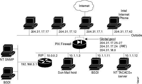
The configuration that follows shows the use of PAT (port address translation), denying Java applets, using the AAA commands, creating a mail host, permitting NFS, initializing SNMP, and setting console access with Telnet and HTTP.
Figure 3-1 Configuring Multiple Features
The configuration is as follows:
1
2
3
4
5
6
7
8
9
10
11
12
13
14
15
16
17
18
19
(Configuration example continues on next page)
Line 1 sets the syslog to send all possible messages to the syslog host in line 3. Line 2 disables displaying messages to the console.
Lines 4 and 5 establish that the network interfaces are Ethernet and that the outside interface uses AUI wiring and that the inside interface uses RJ-45 10baseT wiring. Lines 6 and 7 assign IP addresses to each interface.
Line 8 sets an ARP timeout to 6400 seconds (one hour and 45 minutes). This is useful when you are setting up a network and changing inside and outside host addresses often.
Lines 9 to 11 create a global pool. Line 10 creates a port address translation address (PAT) that permits up to 16000 hosts to share this IP address.
Lines 12 and 13 specify lists of inside hosts that can use the firewall for address translation.
Lines 14 to 17 create access lists to determine which hosts can access services. In line 14, denies host 3.3.3.3 from accessing H323 (port 1720) services such as MS NetMeeting or InternetPhone. Line 15 denies all hosts from accessing the web (port 80). Line 16 lets host 3.3.3.3 use the web, but denies its users from downloading Java applets.
Line 17 permits host 10.1.1.11 access to the web and to download Java applets. This permit statement outweighs the previous deny regardless of the order in which the statements are entered into the configuration.
Lines 18 and 19 specify that the access lists in lines 14 to 17 pertain to connections started on the inside network to access outside services.
Configuration Example (Continued)
20
21
22
23
24
25
26
27
28
29
30
31
32
33
34
(Configuration example continues on next page)
Lines 20 and 21 disable outside interface RIP listening and broadcasting of a default route. Line 22 enables inside interface RIP listening and broadcasting a default route.
Line 24 sets the default route to 204.31.17.1. (0 is an abbreviation for 0.0.0.0.) Line 25 creates a static route.
Lines 26 to 28 establish outbound connection authentication and authorization using TACACS+.
Line 29 creates a net static. Line 30 allows users on the Internet to send InternetPhone requests to users on 3.3.3.x while addressing them as 204.31.17.x.
Line 31 and line 32 shows the use of the connection limit and the embryonic limit arguments. The maximum number of connections limits the number of connections a host can use. These two 1ines permit access to the web server for only 10 users and up to 30 SYNs. Note that static maximum connections option applies to both inbound and outbound connections so if 30 SYN flooders come in, the web server cannot go out itself.
Line 33 opens the RPC portmapper on UDP port 111. Refer to the UNIX /etc/rpc file and rpc(3N) for more information. Once you create a conduit for RPC, you can use the following command from the outside 204.31.17.67 to track down the activity of a PCNFSD on RPC 150001:
rpcinfo -u 204.31.17.25 150001Another use of RPC is with the following command to see the exports of 204.31.17.25 if you want to allow NFS mounting from outside in.
showmount -e 204.31.17.25
Note
Line 34 permits NFS access between the outside and inside, such that 204.31.17.17 can mount 10.1.1.11.
Configuration Example (Continued)
35
36
37
38
39
40
41
42
Line 35 designates an SMTP mail host. The Mail Guard feature in PIX Firewall defines that only the seven commands described in section 4.5.1 of RFC 821 be permitted for access to the mail host. (The commands are HELO, MAIL, RCPT, DATA, RSET, NOOP, and QUIT.) The mailhost command in Line 35 makes the mail server on 10.1.1.3 visible on 204.31.17.25 with 10 maximum connections and up to 11 embryonic connections.
The Internet MX record for pine.com in this case should point to 204.31.17.25.
Line 36 creates a conduit for port 113, the IDENT protocol. If the mail server has to talk to many mail servers on the outside which connects back with the now obsolete and highly criticized IDENT protocol, use this conduit to speed up mail transmission.
Lines 37 to 39 specify the SNMP server IP address, the server's location, and the name of its administrator.
Lines 40 and 41 permit host access to the PIX Firewall console. Line 40 permits a single host, 10.1.1.11 to access the console with Telnet. The 255 value in the last octet of the netmask means that the specified host can access the console.
Line 41 permits console access for up to 255 users on the 3.3.3.0 network. The 0 value in the last octet of the netmask permits all hosts in that address access. However, Telnet only permits 16 hosts simultaneous access to the PIX Firewall console over Telnet.
Line 42 permits the specified host to access the PIX Firewall management interface.
Configuring Failover
Use the failover command without an argument after you connect the optional failover cable between your primary firewall and a secondary firewall. The default is failover on. Enter no failover in the configuration file for PIX Firewall if you will not be using the failover feature. Use the show failover command to verify the status of the connection and to determine which unit is active.
Failover works by passing control to the secondary unit should the primary unit fail. For Ethernet, failover detection should occur within 15 seconds.
The markings on the cable let you choose which unit is primary and which is secondary. Refer to Installing the Failover Connector Assembly and Cable (Document Number 78-3749-02) supplied with the failover cable option for more information about upgrading a PIX Firewall unit to accept the failover cable. PIX Firewall units manufactured after November 1996 come equipped with the failover cable connectors; for these units, you need only read Installing the Failover Connector Assembly and Cable to see how to connect the failover cable between units.
Note
Failover only works with the Cisco failover cable.Enable the failover feature by adding the failover command (without the active parameter) to the configuration files for both the primary and secondary PIX Firewall units.
When you use Telnet to access the PIX Firewall, only the active unit serves the connection. Use the hostname command on both units to identify a unique name for each unit. Using the host name, you can tell if you are communicating with the primary or secondary unit. If you are using Telnet when a failure occurs, you need to disconnect the Telnet session and restart it to the IP address.
If a failure occurs, the host name in the telnet command prompt gives you positive acknowledgment that the secondary unit is active. In addition, SYSLOG messages indicate whether the primary or secondary unit failed. Use the show failover command to verify which unit is active.
If you want to force a PIX Firewall to be active or go to standby you can use the failover active or no failover active command. Use this feature to force a PIX Firewall offline for maintenance or to return a failed unit to service.
Use the show failover command to verify the status of the connection and to determine which unit is active.
Configuring Both Firewall Units for Failover
Follow these guidelines for configuring both units the same:
•
•
•
•
•
•
Frequently Asked Questions
This section contains some frequently asked questions about the failover feature.
•
There is currently no initialization shared between the two units other than the state of failover (On/Off & Active/Standby) and the MAC address of the primary unit. When a unit boots up it defaults to Failover On and Secondary, unless "no failover" has been saved in the configuration. It then checks to see if the failover cable is present. If the cable is not present the unit automatically becomes the active unit. If the cable is present the unit that has the primary end of the failover cable plugged into it becomes the primary unit by default. The primary unit's MAC address is then given to the secondary unit.
•
The easiest thing to do is save the configuration on the primary unit to diskette, and copy it to the secondary unit.
•
Fault detection is based on the following:
•
•
•
•
•
•
•
•
A switch can be initiated by either unit. When a switch takes place each unit changes state. The newly active unit starts accepting traffic while the new standby unit stops accepting traffic. The two units do not share connection states. Any active connections will be dropped when a failover switch occurs. The clients must re-establish the connections through the newly active unit.
•
SYSLOG messages will be generated when any errors or switches occur. Evaluate the failed unit and fix or replace it.
Failover SYSLOG Messages
In the messages that follow, P|S can be either Primary or Secondary depending on which PIX Firewall is sending the message. Failover messages always have a SYSLOG priority level of 2, which indicates critical condition. Refer to the syslog output command description for more information on SYSLOG messages.
The SYSLOG messages sent to record failover events are:
•
•
•
•
•
•
•
•
•
•
•
•
•
•
•
•
•
Configuring Failover to Handle Switch Failure
Step 1
Step 2
(a)
(b)
(c)
Caveat: If the firewall pair is also plugged into a switch (not a hub) at the DMZ, the DMZ switch may not see the standby firewall until traffic from the internal net goes through the standby firewall, then to the DMZ switch. So imagine this: failover will occur, but traffic incoming from the DMZ will be blocked (still goes to the dead firewall) until outgoing traffic from the internal net wakes up the DMZ switch.
Another caveat: After failover, the standby PIX Firewall is now using the SPAN port as a regular Ethernet port. But, a SPAN port is not considered a "normal" Ethernet port (see the Catalyst 5000 documentation). Traffic flows through the SPAN port as if it were a normal port.
What about using SPAN across two switches? This cannot work because when you use a trunk port as the source of a SPAN port, ISL frames stay intact. ISL frames are not the same frames the active firewall sees, so the standby firewall sees different traffic: an illegal situation.
Step 3
Configuring Private Link
The link command creates an encrypted path between version 4 Private Link-equipped PIX Firewall units. You can specify up to seven encryption keys for data access between your unit and the remote unit. The key-ID and key values must be the same on each side of the Private Link. Once you specify the same keys on both sides of the connection, the systems alert each other when a new key takes effect. You can use the age command to specify the number of minutes that a key is in effect.
Specify the link command once for each key you want to specify; for example, if you want seven keys, enter the link command in the configuration seven times.
The PIX Firewall Private Link consists of an encryption card and software that permits PIX Firewall units to provide encrypted communications across an unsecure network such as the Internet. This optional feature is available to domestic customer sites.
PIX Firewall allows up to 256 Private Links. At least two PIX Firewall units are required along with the hardware/software option to use this feature.
Private Link works by checking packets that arrive at the PIX Firewall inside interface. If a route link previously created by the linkpath command exists that matches the destination network address, the packet is encrypted and encapsulated in an AH/ESP frame. The frame has a destination address of the remote PIX Firewall and a source address of the local PIX Firewall. When the packet arrives at the remote PIX Firewall unit, the data in the packet is decrypted and then sent through the inside interface to the original IP address specified. No translation takes place on packets that traverse the PIX Firewall Private Link. The addressing and data remains completely unchanged.
PIX Firewall allows up to 512 link paths.
You can manage remote PIX Firewall units through the Private Link interface.
Example
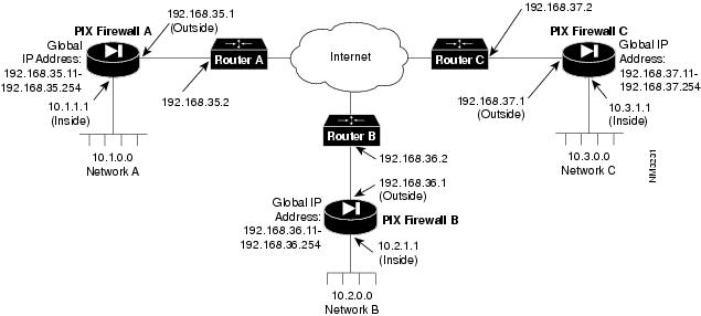
To configure a Private Link, refer to the example setup in .
Figure 3-2 Example Private Link Network Diagram
Before configuring Private Link, you would initially configure the systems using the standard commands.
To configure PIX Firewall A, use these commands:
pixfirewall(config)# interface ethernet inside autopixfirewall(config)# interface ethernet outside autopixfirewall(config)# ip address inside 10.1.1.1 255.255.255.0pixfirewall(config)# ip address outside 192.168.35.1 255.255.255.0pixfirewall(config)# global 1 192.168.35.11-192.168.35.254pixfirewall(config)# nat 1 0.0.0.0pixfirewall(config)# route inside 0.0.0.0 0.0.0.0 10.1.1.2 1pixfirewall(config)# route outside 0.0.0.0 0.0.0.0 192.168.35.2 1For this example, assume that PIX Firewall B, the version 2 PIX Firewall, is already configured to have the IP addresses and global IP addresses shown in the illustration, and that it has its Private Link configured to talk to PIX Firewall A and C. Refer to the version 2 Private Internet Exchange Reference Guide (Document Number 78-3362-02) for more information on configuring Private Link.
To initially configure PIX Firewall C, use these commands:
pixfirewall(config)# interface ethernet inside autopixfirewall(config)# interface ethernet outside autopixfirewall(config)# ip address inside 10.3.1.1 255.255.255.0pixfirewall(config)# ip address outside 192.168.37.1 255.255.255.0pixfirewall(config)# global 1 192.168.37.11-192.168.37.254pixfirewall(config)# nat 1 0.0.0.0pixfirewall(config)# route inside 0.0.0.0 0.0.0.0 10.3.1.2 1pixfirewall(config)# route outside 0.0.0.0 0.0.0.0 192.168.37.2 1When you configure a Private Link, follow these steps:
Step 1
Step 2
Step 3
Step 4
On PIX Firewall A, in the previous illustration, enter these commands to configure the Private Link:
pixfirewall(config)# : Configure for firewall C:pixfirewall(config)# link 192.168.37.1 1 fadebacfadebacpixfirewall(config)# link 192.168.37.1 2 bacfadefadebacpixfirewall(config)# link 192.168.37.1 3 baabaaafadebacpixfirewall(config)# link 192.168.37.1 4 beebeeefadebacpixfirewall(config)# linkpath 10.3.0.0 255.255.255.0 192.168.37.1pixfirewall(config)# :pixfirewall(config)# : Configure for firewall B:pixfirewall(config)# lnko 192.168.36.2 fadebacfadebacpixfirewall(config)# lnkopath 10.2.0.0 255.255.255.0 192.168.36.2On PIX Firewall C, enter these commands:
pixfirewall(config)# : Configure for firewall A:pixfirewall(config)# link 192.168.35.1 1 fadebacfadebacpixfirewall(config)# link 192.168.35.1 2 bacfadefadebacpixfirewall(config)# link 192.168.35.1 3 baabaaafadebacpixfirewall(config)# link 192.168.35.1 4 beebeeefadebacpixfirewall(config)# linkpath 10.1.0.0 255.255.255.0 192.168.35.1pixfirewall(config)# :pixfirewall(config)# : Configure for firewall B:pixfirewall(config)# lnko 192.168.36.2 fadebacfadebacpixfirewall(config)# lnkopath 10.2.0.0 255.255.255.0 192.168.36.2
Note
Configuring SNMP
The snmp-server command causes the PIX Firewall to send SNMP traps so that the firewall can be monitored remotely. Use snmp-server host to specify which systems receive the SNMP traps. You can specify up to five systems and all must be on the inside network of the firewall. PIX Firewall converts the contact and location information to lowercase.
Note
The SNMP server must be on the inside network.
PIX Firewall does not support browsing of the Cisco SYSLOG MIB. The only MIBs you can browse are System and Interfaces.Use snmp-server contact and snmp-server location to specify your name and the location of the PIX Firewall so that hosts receiving SNMP traps can contact you if monitored problems occur.
Using SNMP, you can monitor system events on the PIX Firewall.
The PIX Firewall SNMP MIB-II groups available are System and Interfaces.
The PIX Firewall SNMP traps available to an SNMP server are:
•
•
•
•
•
•
Use CiscoWorks Windows (Product Number CWPC-2.0-WIN) or any other SNMP V1, MIB-II compliant browser to receive SNMP traps and browse a MIB. SNMP traps occur at UDP port 162. Up to five hosts can receive SNMP traps. SNMP events can be read, but information on the PIX Firewall cannot be changed with SNMP.
Compiling Cisco SYSLOG Enterprise MIB Files
To receive security and failover SNMP traps from the PIX Firewall, compile the Cisco SYSLOG MIB into your SNMP management application. If you do not compile the Cisco SYSLOG MIB into your application, you only receive MIB-II traps for link up or down, and firewall cold and warm start.
To compile Cisco SYSLOG Enterprise MIB files into your browser using CiscoWorks for Windows (SNMPc), complete the following steps:
Step 1
Step 2
Step 3
Step 4
Step 5
Step 6
Step 7
Step 8
Step 9
Step 10
Step 11
Note
Configuring SYSLOG
The syslog output command configures the facility and level of SYSLOG messages. Because network devices share the eight facilities, syslog output lets you set the facility marked on all messages. Messages are sent to the SYSLOG host over UDP. The syslog output command also starts sending messages onto the network. Use the syslog host command to specify which systems receive the messages.
You can use show syslog to view previously sent messages.
PIX Firewall generates SYSLOG messages for system events, such as security alerts and resource depletion. SYSLOG messages may be used to create email alerts and log files, or displayed on the console of a designated host using UNIX SYSLOG conventions.
A PC WinSock version of syslogd also will work.
Note
The SYSLOG server must be on the inside network.
PIX Firewall sends SYSLOG messages only to a single file on the receiving system.PIX Firewall sends SYSLOG messages to document the following events:
•
•
•
•
Logging is enabled by configuring the PIX Firewall with the IP address of the log host.
The syslog output command syntax lets you specify the SYSLOG facility and level for how messages are sent to the SYSLOG host.
The facility consists of eight facilities LOCAL0(16) through LOCAL7(23); the default is LOCAL4(20). Hosts file the messages based on the facility number in the message.
The level specifies the message type; sets the level above which PIX Firewall suppresses messages to the SYSLOG hosts. Setting the level to 3, for example, allows messages with levels 0, 1, 2, and 3 to display. The default is 3. The levels are:
•
•
•
•
•
•
•
•
Configuring a UNIX System for SYSLOG
To configure a UNIX system to accept SYSLOG messages:
Step 1
Step 2
# mkdir /var/log/pix# touch /var/log/pix/pixfirewallStep 3
In the syslog.conf file, you code each selector and action pair for the messages you want to receive. For example, if you want to receive messages in a file called pixfirewall for message priorities 0, 1, 2, and 3, and you use the default LOCAL4 facility, the syslog.conf statements would be:
# PIX Firewall SYSLOG messages (formerly A.S. violations)local4.emerg /var/log/pix/pixfirewalllocal4.alert /var/log/pix/pixfirewalllocal4.crit /var/log/pix/pixfirewalllocal4.error /var/log/pix/pixfirewallThis configuration directs PIX Firewall SYSLOG message to the specified file. Alternatively, if you want the message sent to the logging host console or emailed to a system administrator, refer to the UNIX syslog.conf(4) manual page.
Note
Entries in /etc/syslog.conf must follow these rules:
(a)
(b)
(c)
Step 4
# cat /etc/syslog.pid92# kill -HUP 92The first command lists the SYSLOG process ID. This number may vary by system. The second command sends SYSLOG the HUP signal to cause it to restart.
pixfirewall(config)# syslog output 23.4Step 5
pixfirewall(config)# syslog output 23.4pixfirewall(config)# syslog host 10.10.10.56Examples of PIX Firewall SYSLOG messages resemble the following:
Oct 15 12:55:03 pix-in PIX out of connections!Oct 15 12:54:28 pix-in conn end faddr 192.168.42.42 fport 4457 gaddr 10.10.10.1 laddr 10.10.10.2Oct 15 13:04:02 pix-in deny tcp out 192.168.96.14 in 10.10.10.42 flags SYN ACKOct 15 13:37:44 pix-in conns 16384 conns_used 0 xlate 254 xlate_used 1Oct 15 13:47:21 pix-in PIX logged in from 10.10.42.112Configuring FTP and URL Logging
Logging of FTP commands and WWW URLs is automatically enabled when SYSLOG is enabled. FTP and URL messages are logged to SYSLOG level 7. The following example output shows what to expect:
Sample URL Log
<166> 192.168.69.71 accessed URL 10.0.0.1/secrets.gifSample FTP Log
<166> 192.168.69.42 Retrieved 10.0.0.42:feathers.tar<166> 192.168.42.54 Stored 10.0.42.69:privacy.zipYou can view these messages at the console with the show syslog command.