Feedback Feedback
|
Table Of Contents
FIPS 140-2 Non-Proprietary Security Policy for the Cisco PIX 525/535 Security Appliance
PIX Security Appliance Validation Level
Physical Characteristics and Module Interfaces
Crypto Officer Guidance - System Initialization
Crypto Officer Guidance - System Configuration
Approved Cryptographic Algorithms
Applying Tamper-Evident Labels
Obtaining Documentation and Submitting a Service Request
FIPS 140-2 Non-Proprietary Security Policy for the Cisco PIX 525/535 Security Appliance
Introduction
This is a non-proprietary Cryptographic Module Security Policy for the Cisco PIX 525 and PIX 535 security appliances, referred to in this document as PIX security appliances, devices, modules, or appliances. This security policy describes how the PIX security appliances meet the security requirements of FIPS 140-2 and how to run the devices in a FIPS 140-2 mode of operation.
This policy was prepared as part of the Level 1 FIPS 140-2 validation of the Cisco PIX 525 and PIX 535 security appliances.
FIPS 140-2 (Federal Information Processing Standards Publication 140-2 — Security Requirements for Cryptographic Modules) details the U.S. Government requirements for cryptographic modules. More information about the FIPS 140-2 standard and validation program is available on the NIST website at http://csrc.nist.gov/cryptval/.
Note
This document may be copied in its entirety and without modification. All copies must include the copyright notice and statements on the last page.
This document includes the following sections:
•
•
•
•
•
Submission Package
This security policy document is part of a complete FIPS 140-2 Submission Package. In addition to this document, the complete FIPS 140-2 Submission Package contains:
•
•
•
With the exception of this Non-Proprietary Security Policy, the FIPS 140-2 Validation Documentation is proprietary to Cisco Systems, Inc. and is releasable only under appropriate non-disclosure agreements. For access to these documents, please contact Cisco Systems, Inc. See "Obtaining Technical Assistance" section on page 21 for more information.
Overview
The Cisco PIX security appliances deliver robust user and application policy enforcement, multi-vector attack protection, and secure connectivity services in cost-effective, easy-to-deploy solutions. Cisco PIX security appliances provide comprehensive security, performance, and reliability for network environments of all sizes.
These PIX security appliances provide multiple integrated security and networking services, including:
•
•
•
•
•
•
The Cisco PIX 525 and PIX 535 security appliances are validated with the VPN Acceleration Card+ (VAC+), to provide hardware-accelerated IP Security (IPSec) VPN support for international cryptographic standards and scalable VPN tunnel aggregation in a solution that comes integrated with, or as an upgrade for, most Cisco PIX security appliances. Ranging from solutions for small to midsize businesses (SMBs) to large enterprises and service providers, the Cisco PIX security appliances offer integrated network security services and investment protection. The Cisco PIX VAC+ offloads VPN cryptographic functionality from the PIX device, enabling the Cisco PIX security appliances to deliver stateful inspection firewall services, advanced application and protocol inspection, inline intrusion protection, and robust multimedia and voice security services.
PIX Security Appliance Validation Level
Table 1 lists the level of validation for each area in the FIPS 140-2 security policy.
Physical Characteristics and Module Interfaces
The design of the Cisco PIX 525 and PIX 535 security appliances supports a combination of 10/100 Fast Ethernet interfaces and Gigabit Ethernet interfaces, with a redundant power supply on PIX 535.
Each PIX security appliance is a multi-chip standalone device. The cryptographic boundary is defined as encompassing the "top," "front," "left," "right," and "bottom" surfaces of the case, as well as the "backplane" of the case not supporting a removable interface or service card, and the inverse of the three-dimensional space within the case that would otherwise be occupied by an installed service card. The cryptographic boundary includes the connection apparatus between the service card and the motherboard/daughterboard that hosts the service card, but the boundary does not include the service card itself (except when a VAC+ is inserted into an available PIX Circuit Board Interface). In other words, the cryptographic boundary encompasses all hardware components within the case of the device except any installed modular service card (except when a VAC+ is inserted into an available PIX Circuit Board Interface).
Each PIX security appliance provides a number of physical and logical interfaces to the device, and the physical interfaces provided by the device are mapped to four FIPS 140-2 defined logical interfaces: data input, data output, control input, and status output.
The logical interfaces and their mapping are described in Table 2 and in Table 3:
Roles and Services
The device can be accessed in one of the following ways.
•
•
•
•
As required by FIPS 140-2, there are two main roles in the PIX security appliance that operators may assume: a crypto officer role and user role. The PIX security appliance supports role-based authentication, and the respective services for each role are described in the "Crypto Officer Services" section, and the "User Services" section.
Crypto Officer Services
The crypto officer role is responsible for the configuration and maintenance of the PIX security appliance and authenticates from the enable command (for local authentication) or the login command (for AAA authentication) from the user services. The crypto officer services consist of the following:
•
•
•
•
•
•
User Services
Basic encryption and decryption services are performed by the User role. A user enters the system by accessing the console port with a terminal program or via IPSec protected telnet or SSH session to a LAN port. The PIX security appliance will prompt the user for their password. If the password is correct, the user is allowed entry to the executive program. The services available to the user role consist of:
•
•
•
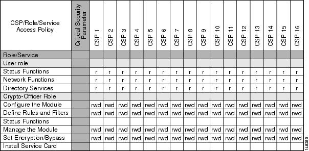
Critical Security Parameters
The services accessing the Critical Security Parameters (CSPs), the type of access and which role accesses the CSPs are listed in the Table 4.
Table 4 Role and Service Access to Security Relevant Data Items
r = read w = write d = delete
Authentication Mechanisms
The PIX security appliance supports either a password or digital certificates for authenticating IPSec users. To log on to the PIX security appliance for management purposes, an operator must connect to it through one of the management interfaces (Console Port, SSH, Telnet, or ASDM) and provide a password.
Table 5 describes the estimated strength of the authentication mechanism.
Table 5 Estimated Strength of Authentication Mechanism
Username Password mechanism
Passwords must be a minimum of 6 characters (see the "Secure Operation" section). The probability of a false positive for a random password guess is less than 1 in 1,000,000. This is also valid for RADIUS or TACACS+ shared secret keys.
The password can consist of alphanumeric values, a-zA-Z0-9, yielding 62 choices per character. The probability of a successful random attempt is 1/62^6, which is less than 1/1,000,000.
Certificate based authentication
The PIX security appliance supports a public key based authentication with 1024 and 2048 (for RSA) bit keys, and thus the probability of a false positive from a random correct guess is less than 1 in 1,000,000.
A 1024-bit RSA key has at least 80-bits of equivalent strength. The probability of a successful random attempt is 1/2^80, is less than 1/1,000,000.
A 2048-bit RSA key has at least 112-bits of equivalent strength. The probability of a successful random attempt is 1/2^112, is less than 1/1,000,000.
Cryptographic Key Management
The PIX security appliances use a variety of critical security parameters during operation.
Table 6 lists the critical security parameters used by the PIX security appliance.
Self-Tests
The PIX security appliances include an array of self-tests that are run during startup and periodically during operations to prevent any secure data from being released and to ensure all components are functioning correctly.
Table 7 lists the PIX security appliance power-on self-tests.
The PIX security appliances perform all power-on self-tests automatically at boot-up when FIPS mode is enabled. All power-on self-tests must be passed before a user/crypto officer can perform services. The power-on self-tests are performed after the cryptographic systems are initialized but prior to the initialization of the LANs; this prevents the device from passing any data during a power-on self-test failure. In the unlikely event that a power-on self-test fails, an error message is displayed on the console followed by a system reboot.
Table 8 lists the conditional self-tests that the PIX security appliance performs.
Mitigation of Other Attacks
The PIX security appliances do not claim to mitigate any attacks in a FIPS-approved mode of operation above and beyond the protection inherently provided by the PIX security appliance.
Secure Operation
The Cisco PIX 525 and PIX 535 security appliances meet FIPS 140-2 Level 1 requirements.
This section describes how to place and keep the PIX security appliance in a FIPS-approved mode of operation. Operating the PIX security appliance without maintaining the settings described in the "Crypto Officer Guidance - System Initialization" section and "Crypto Officer Guidance - System Configuration" section will remove the PIX security appliance from the FIPS-approved mode of operation.
The Crypto Officer must ensure that the PC that is used for the console connection is a stand-alone or a non-networked PC.
Crypto Officer Guidance - System Initialization
The PIX security appliances were validated with software version 7.0.4. This is the only allowable image for FIPS-approved mode of operation.
Initialize the system using the procedure below:
Step 1
(config)#mode singleStep 2
(config)#no firewall transparentStep 3
(config)#crashinfo console disableStep 4
(config)#fips enableStep 5
Step 6
(config)#no service password-recoveryStep 7
(config)#config-register 0x10011Step 8
(config)#failover key hex <key>
Note
- Before upgrading to V7.0.4, copy the configuration to a location off the device
- Use a text editor to modify the interface configuration
- Change the failover cables to the specified failover interface
- Upgrade to V7.0.4 and reload the modified configurationStep 9
(config-terminal)#aaa authentication serial console LOCAL(config-terminal)#username <name> password <password>Step 10
(config-terminal)#aaa authentication ssh console LOCAL(config-terminal)#aaa authentication telnet console LOCALStep 11
(config-terminal)#aaa authentication enable console LOCALStep 12
(config-terminal)#username <name> password <password> privilege 15(config-terminal)#username <name> password <password> privilege 1Step 13
Step 14
Note
Step 15
Step 16
Crypto Officer Guidance - System Configuration
Configure the system using the following procedure:
Step 1
Step 2
Note
Step 3
•
(config)# ssl server-version tlsv1-only•
•
Step 4
(config)# ssh version 2
Note
Step 5
Step 6
Step 7
Step 8
Step 9
Step 10
Step 11
Step 12
Approved Cryptographic Algorithms
The PIX security appliances support many different cryptographic algorithms. However, only the following FIPS-approved algorithms may be used:
•
•
•
•
•
•
•
In addition, the following algorithms are FIPS-allowed:
•
•
Note
Each cryptographic implementation in the PIX security appliance software release with on-board acceleration has achieved the certifications listed in Table 9.
Non-FIPS Approved Algorithms
The PIX security appliances implement the following non-FIPS-approved cryptographic algorithms:
•
•
•
•
•
•
•
Applying Tamper-Evident Labels
All Critical Security Parameters (CSPs) are stored and protected within the PIX security appliance tamper-evident enclosure. The administrator is responsible for properly placing all tamper-evident labels to comply with the FIPS 140-2 security policy. The security labels mandatory for FIPS 140-2 compliance are provided in FIPS Kit (CVPNPIXASAFIPS/KIT). These security labels are very fragile and cannot be removed without clear signs of damage to the labels.
The crypto officer should inspect the tamper-evident labels periodically to verify they are intact and the serial numbers on the applied tamper-evident labels match the records in the security log.
Note
Apply the serialized tamper-evident labels by performing the steps in either the "PIX 525" section or the "PIX 535" section.
PIX 525
Step 1
Step 2
Step 3
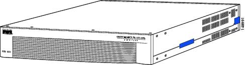
Figure 1 Cisco PIX 525 Front Tamper-Evident Label Placement
Step 4
Step 5
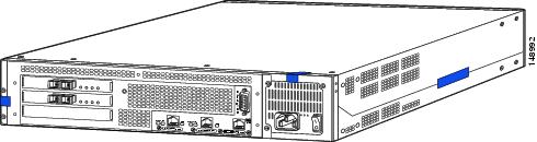
Figure 2 Cisco PIX 525 Back Tamper-Evident Label Placement
Step 6
PIX 535
Step 1
Step 2
Step 3
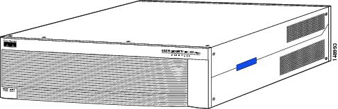
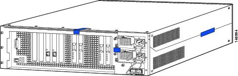
Figure 3 Cisco PIX 535 Front Tamper-Evident Label Placement
Step 4
Figure 4 Cisco PIX 535 Back Tamper-Evident Label Placement
Step 5
Related Documentation
This document deals only with operations and capabilities of the PIX security appliance in the technical terms of a FIPS 140-2 cryptographic device security policy.
More information is available on the PIX security appliance from the following sources:
•
•
•
Obtaining Documentation and Submitting a Service Request
For information on obtaining documentation, submitting a service request, and gathering additional information, see the monthly What's New in Cisco Product Documentation, which also lists all new and revised Cisco technical documentation, at:
http://www.cisco.com/en/US/docs/general/whatsnew/whatsnew.html
Subscribe to the What's New in Cisco Product Documentation as a Really Simple Syndication (RSS) feed and set content to be delivered directly to your desktop using a reader application. The RSS feeds are a free service and Cisco currently supports RSS Version 2.0.
Definitions
AES—Advanced Encryption Standard
CMVP—Cryptographic Module Validation Program
CSP—Critical Security Parameter
DES—Data Encryption Standard
DSA—Digital Signature Algorithm
FIPS—Federal Information Processing Standard
HMAC—Hashed Message Authentication Code
HTTP—Hyper Text Transfer Protocol
IKE—Internet Key Exchange
KAT—Known Answer Test
LED—Light Emitting Diode
MAC—Message Authentication Code
NIST—National Institute of Standards and Technology
NVLAP—National Voluntary Laboratory Accreditation Program
NVRAM—Non-volatile Random Access Memory
PRNG—Pseudo-Random Number Generator
RAM—Random Access Memory
RSA—Rivest Shamir and Adleman method for asymmetric encryption
Service Card—A service card may provide additional interfaces, feature acceleration or additional services. Service cards may take a Circuit Board form factor for PIX security appliances
SHA—Secure Hash Algorithm
SSL—Secure Sockets Layer
TLS—Transport Layer Security
Trustpoint—A trustpoint represents a CA identity and possibly a device identity, based on a certificate issued by the CA. When certificates are exchanged, the PIX/ASA device follows the trustpoint path upwards until it reaches the root CA to validate the certificate.