Feedback
Table Of Contents
Configuring High Availability (HA)
Adding High Availability Cisco NAC Appliance To Your Network
Installing a Clean Access Manager High Availability Pair
CAM High Availability Overview
Connect the Clean Access Manager Machines
Configure the HA-Secondary CAM
Upgrading an Existing Failover Pair
Accessing High Availability Pair CAM Web Consoles
Determining Active and Standby CAM
Determining Primary and Secondary CAM
Installing a Clean Access Server High Availability Pair
CAS High Availability Overview
CAS High Availability Requirements
Selecting and Configuring the Heartbeat UDP Interface
Serial Port High-Availability Connection
Configure the HA-Primary Clean Access Server
Configure the HA-Secondary Clean Access Server
Connect the Clean Access Servers and Complete the Configuration
Modifying CAS High Availability Settings
To Change IP Settings for an HA-CAS
Upgrading an Existing Failover Pair
Configuring High Availability for Virtual Gateway Mode
Heartbeat/Link-Based Connections
Accessing High Availability Pair CAS Web Consoles
Determining Active and Standby CAS
Determining Primary and Secondary CAS
Configuring High Availability (HA)
This chapter covers the following topics:
•
Adding High Availability Cisco NAC Appliance To Your Network
•
•
•
Adding High Availability Cisco NAC Appliance To Your Network
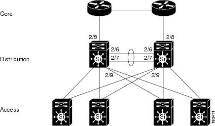
The following diagrams illustrate how HA-CAMs and HA-CASs can be added to an example core-distribution-access network (with Catalyst 6500s in the distribution and access layers).
Figure 4-1 shows a network topology without Cisco NAC Appliance, where the core and distribution layers are running HSRP (Hot Standby Router Protocol), and the access switches are dual-homed to the distribution switches.
Figure 4-1 Example Core-Distribution-Access Network Before Cisco NAC Appliance
Note
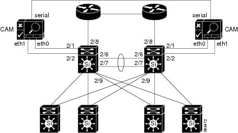
Figure 4-2 shows how HA-CAMs can be added to the core-distribution-access network. In this example, the HA heartbeat connection is configured over both serial and eth1 interfaces.
Figure 4-2 Adding HA CAMs to Network
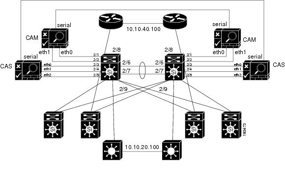
Figure 4-3 shows how HA-CASs can be added to the core-distribution-access network. In this example, the CAS is configured as an L2 OOB Virtual Gateway in Central Deployment. The HA heartbeat connection is configured over both a serial interface and a dedicated eth2 interface. Link-failure based failover connection can also be configured over the eth0 and/or eth1 interfaces.
Note
Figure 4-3 Adding HA CAS to Network
Installing a Clean Access Manager High Availability Pair
This section describes how to set up a pair of Clean Access Manager machines for high-availability. By deploying Clean Access Managers in high-availability mode, you can ensure that important monitoring, authentication, and reporting tasks continue in the event of an unexpected shutdown. Topics include:
•
•
•
•
•
Note
CAM High Availability Overview
Caution
For more information, see the "HA Active-Active Situation Due to Expired SSL Certificates" section of the Cisco NAC Appliance - Clean Access Manager Configuration Guide, Release 4.9(2).
The following key points provide a high-level summary of HA-CAM operation:
•
•
Note
•
•
•
•
•
•
•
•
•
•
Note
Note
Note
Caution
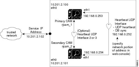
Figure 4-4 illustrates a sample configuration.
Figure 4-4 Clean Access Manager Example High-Availability Configuration
The Clean Access Manager high-availability mode is an Active/Passive two-server configuration in which a standby Clean Access Manager machine acts as a backup to an active Clean Access Manager machine. While the active CAM carries most of the workload under normal conditions, the standby monitors the active CAM and keeps its data store synchronized with the active CAM's data.
If a failover event occurs, such as the active CAM shuts down or stops responding to the peer's "heartbeat" signal, the standby assumes the role of the active CAM.
When first configuring the HA peers, you must specify an HA-Primary CAM and HA-Secondary CAM. Initially, the HA-Primary is the active CAM, and the HA-Secondary is the standby (passive) CAM, but the active/passive roles are not permanently assigned. If the primary CAM goes down, the secondary (standby) becomes the active CAM. When the original primary CAM restarts, it assumes the backup role.
Note
When the Clean Access Manager starts up, it checks to see if its peer is active. If not, the starting CAM assumes the active role. If the peer is active, on the other hand, the starting CAM becomes the standby.
You can configure two Clean Access Managers as an HA pair at the same time, or you can add a new Clean Access Manager to an existing standalone CAM to create a high-availability pair. In order for the pair to appear to the network as one entity, you must specify a Service IP Address to be used as the trusted interface (eth0) address for the HA pair. This Service IP address is also used to generate the SSL certificate.
To create the Heartbeat UDP Interface link over which HA information is exchanged, you connect the eth1 ports of both CAMs and specify a private network address not currently routed in your organization (the default Heartbeat UDP interface IP address is 192.168.0.252). The Clean Access Manager then creates a private, secure two-node network for the eth1 ports of each CAM to exchange UDP heartbeat traffic and synchronize databases.
Note
Note
Warning
Note
The following sections describe the steps for setting up high availability.
Note
Before Starting
Before configuring high availability, ensure that:
•
Note
•
•
•
•
•
•
•
•
•
The following procedures require you to reboot the Clean Access Manager. At that time, its services will be briefly unavailable. You may want to configure an online CAM when downtime has the least impact on your users.
Note
Connect the Clean Access Manager Machines
There are two types of connections between HA-CAM peers: one for exchanging runtime data relating to the Clean Access Manager activities and one for the heartbeat signal. In High Availability, the Clean Access Manager always uses the eth1 interface for both data exchange and heartbeat UDP exchange. When the UDP heartbeat signal fails to be transmitted and received within a certain time period, the standby system takes over. In order to provide an extra measure of heartbeat redundancy, Cisco recommends you use more Ethernet interfaces in addition to eth1 (mandatory) interface for heartbeat exchange. In order for a failover to occur, all configured heartbeat interfaces must report heartbeat exchange failure. (The eth0 and eth2/eth3 can be used for additional heartbeat interfaces.) Note, however, that the eth1 connection between the CAM peers is mandatory.
Physically connect the peer Clean Access Managers as follows:
•
•
•
Note
Serial Connection
By default, the first serial port detected on the CAM server is configured for console input/output (to facilitate installation and other types of administrative access).
If the machine has only one serial port (COM1 or ttyS0), you can reconfigure the port to serve as the high-availability heartbeat connection. This is because, after the CAM software is installed, SSH or KVM console can always be used to access the command line interface of the CAM.
Note
Caution
WarningConfigure the HA-Primary CAM
Once you have verified the prerequisites, perform the following steps to configure the Clean Access Manager as the HA-Primary for the high availability pair. See Figure 4-4 for an example high-availability configuration.
Step 1
Note
If using a temporary certificate for the HA pair:
a.
b.
c.
If using a CA-signed certificate for the HA pair:
Note
a.
b.
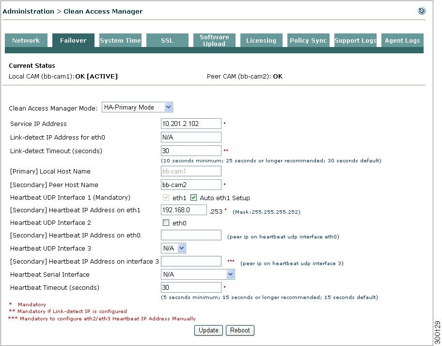
Step 2
Figure 4-5 HA-Primary Clean Access Manager Failover Settings
Step 3
Step 4
Step 5
a.
b.
Note
Step 6
rjcam_1andrjcam_2). Type the host name of the HA-Primary CAM in the Host Name field under Administration > CCA Manager > Network, and type the host name of the HA-Secondary CAM in the Peer Host Name field under Administration > CCA Manager > Failover.
Note
•
Step 7
Note
WarningStep 8
Step 9
Note
Step 10
Note
Step 11
After the Clean Access Manager restarts, make sure that the CAM machine is working properly. Check to see if the Clean Access Servers are connected and new users are being authenticated.
Configure the HA-Secondary CAM
Step 1
Step 2
•
•
Step 3
If using a temporary certificate for the HA pair:
a.
b.
c.
If using a CA-signed certificate for the HA pair:
a.
b.
c.
For more information, see the "Manage CAM SSL Certificates" section of the Cisco NAC Appliance - Clean Access Manager Configuration Guide, Release 4.9(2).
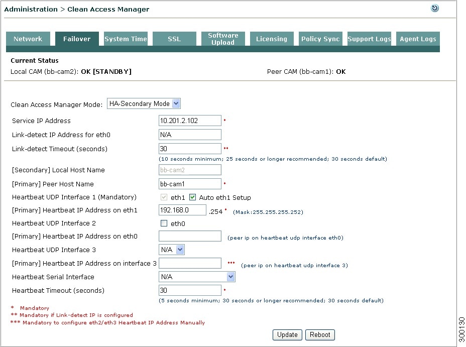
Step 4
Figure 4-6 HA-Secondary Clean Access Manager Failover Settings
Step 5
Note
Step 6
Step 7
Step 8
a.
b.
Note
Step 9
Step 10
Note
WarningStep 11
Step 12
Note
Step 13
Note
WarningStep 14
When the standby CAM starts up, it automatically synchronizes its database with the active CAM.
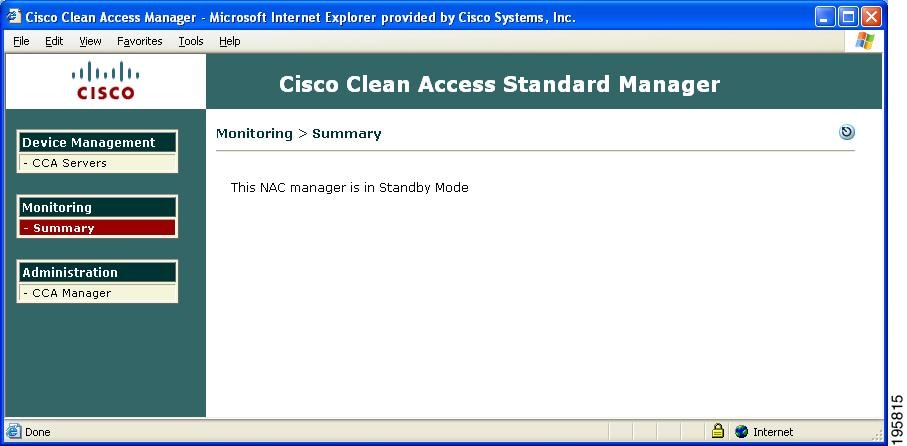
Step 15
Figure 4-7 Standby Web Admin Console Example—Summary Page
Figure 4-8 Standby Web Admin Console Example—CCA Manager > Network Page
Complete the Configuration
Verify settings in the Failover pages for both the active and standby CAMs. The high availability configuration is now complete.
Upgrading an Existing Failover Pair
For instructions on how to upgrade an existing failover pair to a new Cisco NAC Appliance release, see "Upgrading High Availability Pairs" in the corresponding Release Notes for Cisco NAC Appliance.
Failing Over an HA-CAM Pair
WarningTo failover an HA-CAM pair, SSH to the active machine in the pair and perform one of the following commands:
•
•
•
This stops all services on the active machine. When heartbeat fails, the standby machine will assume the active role. Perform service perfigo start to restart services on the stopped machine. This should cause the stopped machine to assume the standby role.
Note
Accessing High Availability Pair CAM Web Consoles
Determining Active and Standby CAM
Access the web console for each CAM in the HA pair by typing the IP address of each individual CAM (not the Service IP) in the URL/Address field of a web browser. You should have two browsers open. The web console for the Standby (inactive) CAM only displays a subset of the module menus and respective submenus available on the Active CAM.
Note
Determining Primary and Secondary CAM
In each CAM web console, go to Administration > CCA Manager > Failover.
•
•
Note
Installing a Clean Access Server High Availability Pair
This chapter describes how to set up two Clean Access Servers in high availability (HA) mode.By deploying Clean Access Servers in high-availability mode, you can ensure that important user authentication and connection tasks continue in the event of an unexpected shutdown. Topics include:
•
•
•
•
•
Note
CAS High Availability Overview
Caution
For more information, see the "HA Active-Active Situation Due to Expired SSL Certificates" section of the Cisco NAC Appliance - Clean Access Server Configuration Guide, Release 4.9(2).
Note
The following key points provide a high-level overview of HA-CAS operation:
•
•
Note
•
•
•
•
•
Note
•
•
•
Caution
Tip
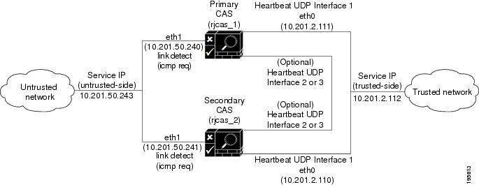
Figure 4-9 illustrates the basic connections in an example HA-CAS configuration.
Figure 4-9 Clean Access Server Example High-Availability Configuration
Note
When first configuring the HA peers, you must specify an HA-Primary CAS and HA-Secondary CAS. Initially, the HA-Primary is the active CAS, and the HA-Secondary is the standby (passive) CAS. If a failover event occurs, such as the active CAS shuts down or stops responding to the peer's heartbeat signal, the standby assumes the role of the active CAS.
Note
When the CAS starts up again, it checks to see if its peer is active. If the peer is active, the starting CAS becomes the standby. If the peer is not active, then the starting CAS assumes the active role.
Typically, Clean Access Servers are configured as an HA pair at the same time, but you can add a new Clean Access Server to an existing standalone CAS to create a high-availability pair. In order for the pair to appear to the network and to the Clean Access Manager as one entity, you must specify a Service IP Address for the trusted interface (eth0) and a Service IP address for untrusted interface (eth1) of the pair.
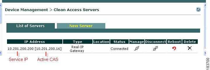
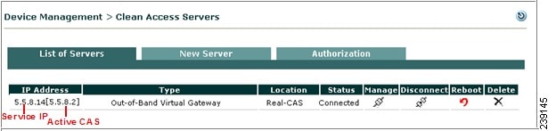
Use the Service IP of the CASs to add the CAS to the CAM. Figure 4-10 shows how the active CAS of a high-availability pair is displayed in brackets next to the Service IP for the pair in the List of Servers in the CAM web console. In addition, either the trusted or untrusted interface Service IP address should be used to generate the SSL certificate.
Figure 4-10 Active CAS in an HA-Pair
Note
Note
Failover Events
•
•
–
–
•
–
–
Note
The status of these ping packets is communicated between the CASs via the heartbeat signal:
–
–
–
•
Choosing External IPs for Link-Based Failover
•
•
•
–
–
–
–
–
Refer to c. Configure HA-Primary Mode and Update and c. Configure HA-Secondary Mode and Update for additional configuration details.
CAS High Availability Requirements
This section describes addition planning considerations when implementing high availability.
Note
For example,-Dperfigo.nat.serviceip=172.10.20.100.
Physical Connection
Cisco recommends using a dedicated connection for failover heartbeat on Clean Access Server high-availability pairs. You can use:
•
Note
If additional network interfaces (e.g. eth2 or eth3) are available, you can use them for UDP heartbeat instead of eth0. In this case, the eth2 or eth3 interfaces on the two machines are connected using a crossover cable. If installing an additional Ethernet interface, configure the IP address for the interface. For instructions, see Configuring Additional NIC Cards.
Switch Interfaces for OOB Deployment
For Out-of-Band deployments, ensure that Port Security is not enabled on the switch interfaces to which the CAS and CAM are connected. This can interfere with CAS HA and DHCP delivery.
Service IP Addresses
In addition to the IP addresses for the trusted and untrusted interfaces for each individual CAS, you will need to provide two Service IP addresses for the trusted and untrusted interfaces of the CAS pair (see Figure 4-9 for an example configuration). A Service IP address is the common IP address that the external network uses to address the pair.
In addition, either the trusted or untrusted interface Service IP address should be used to generate the SSL certificate. If a CAS was previously configured and added to the CAM as a standalone CAS, it must be deleted prior to configuring it for HA.
After HA configuration is complete on both CASs, use the Service IP in the New Server form to add the HA-CAS pair to the CAM. Note that the HA-CAS pair is automatically added as the same Server Type (for example, Out-of-Band Virtual Gateway).
Host Names
For heartbeat, each CAS needs to have a unique hostname (or node name). For HA CAS pairs, this host name will be provided to the peer, and must be resolved via DNS or added to the peer's /etc/hosts file.
DHCP Synchronization
When you configure two CASs that also perform DHCP functions for your deployment as an HA pair, Cisco NAC Appliance automatically synchronizes and exchanges the required keys between the HA-Primary and HA-Secondary CASs to ensure DHCP continues to work properly following a failover event.
SSL Certificates
As in standalone mode, in HA mode the Clean Access Servers can use either a temporary, self-signed certificate or a CA (Certificate Authority)-signed certificate. A temporary certificate is useful for testing or development. A production deployment should have a CA-signed certificate. Considerations in either case are:
1.
2.
3.
4.
Note
Note
If the CAS is the DHCP server and failover occurs, user A also retains his/her assigned IP address because to HA CASs do directly exchange DHCP failover information.
Note
Before Starting
1.
2.
3.
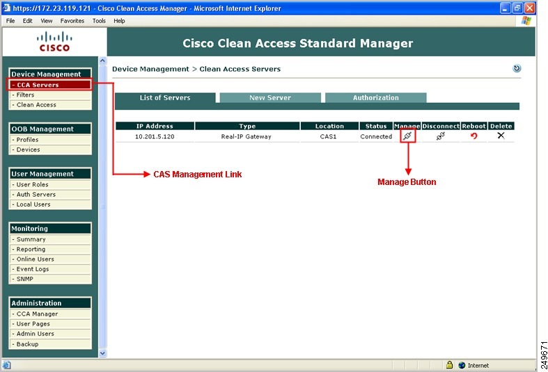
Figure 4-11 List of Servers
Note
Selecting and Configuring the Heartbeat UDP Interface
Note
The Heartbeat UDP interface, if specified, is used to send UDP heartbeat traffic related to high availability. The interface used depends on the interfaces available on the server machine and the load level expected. This interface can use either a dedicated Ethernet interface (such as eth2 or eth3) or the trusted interface eth0, if a dedicated interface is not available.
When using an additional Ethernet interface, you must manually configure the interface using the CAS CLI. There are no eth2 or eth3 configuration settings (IP address, netmask, etc.) available via the CAS web console. For instructions, see Configuring Additional NIC Cards. When a dedicated interface is used, the dedicated interfaces on both machines should be connected using a crossover cable.
Servers running a CAS typically use both available interfaces (eth0 and eth1), with eth0 configured as the trusted network interface. Cisco recommends using the eth2 and eth3 interfaces for heartbeat redundancy, thus freeing up the eth0 and eth1 interfaces to handle Cisco NAC Appliance traffic.
Note
Serial Port High-Availability Connection
By default, the first serial connector detected on the server is configured for console input/output (to facilitate installation and other types of administrative access).
Warning
Caution
When high-availability mode is selected, the serial console login (ttyS0) is automatically disabled to free the serial port for HA mode. To re-enable ttyS0 as the console login, deselect the Disable Serial Login checkbox on the Failover > General tab after clicking Update and before clicking Reboot. For details, see steps c. Configure HA-Primary Mode and Update and c. Configure HA-Secondary Mode and Update.
Configure High Availability
Note
The following sections describe how to set up high availability in four general procedures:
•
•
•
•
Note
"Active/Standby" denotes the runtime status of the server.
Configure the HA-Primary Clean Access Server
The general sequence to configure the HA-Primary CAS is as follows:
a. Access the HA-Primary CAS Directly
b. Configure the Host Information for the HA-Primary CAS
c. Configure HA-Primary Mode and Update
d. Configure the SSL Certificate
f. Add the CAS to the CAM Using the Service IP
When done, continue to Configure the HA-Secondary Clean Access Server.
a. Access the HA-Primary CAS Directly
Each Clean Access Server has its own web admin console that allows configuration of certain limited Administration settings directly on the CAS. The CAS direct access web console must be used to configure CAS pairs for HA.
To access the HA-Primary Clean Access Server's direct access web admin console:
1.
2.
Note
•
b. Configure the Host Information for the HA-Primary CAS
3.
4.
Note
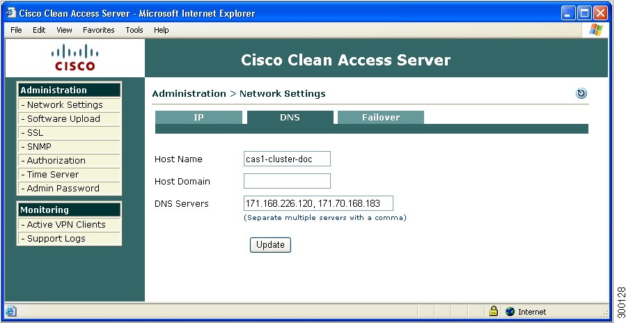
Figure 4-12 DNS Tab
c. Configure HA-Primary Mode and Update
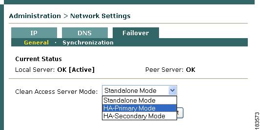
5.
Figure 4-13 Failover —Choose Mode
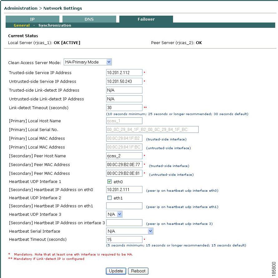
6.
Figure 4-14 Failover —HA-Primary Mode
–
–
•
•
Note
•
Note
0-for no addresses
1-for either trusted/untrusted
2-for both trusted/untrusted
If the Standby CAS can reach more nodes than the Active CAS, the Standby CAS will take over and become the Active CAS. If both CASs can ping the same number of addresses (all addresses or only one address), no failover event occurs, since neither CAS has the advantage. To enable link-detect, enter at least one link-detect IP address on each CAS and a link-detect timeout. See also Choosing External IPs for Link-Based Failover for further details.
Note
The CAS performs Heartbeat connection and (optionally) Link-detect according to the same interval, approximately every 1-2 seconds.•
•
•
•
Note
•
•
•
•
•
•
•
•
•
Note
•
Note
Note
•
Note
Another method you can use to avoid this scenario is to ensure you use an additional Ethernet interface link (eth2, eth3) for heartbeat monitoring between your CAS Ha pair nodes. See Heartbeat UDP Interface 2 and Heartbeat UDP interface 3, above and Configuring Additional NIC Cards, for more information.•
•
d. Configure the SSL Certificate
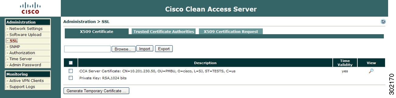
7.
Figure 4-15 Administration > SSL > X509 Certificate
8.
If using a temporary certificate for the HA pair:
a.
b.
c.
If using a CA-signed certificate for the HA pair:
Note
a.
b.
Note
e. Reboot the HA-Primary CAS
9.
f. Add the CAS to the CAM Using the Service IP
10.
11.
12.
Configure the HA-Secondary Clean Access Server
Note
The general sequence to configure the HA-Secondary CAS is as follows:
a. Access the HA-Secondary CAS Directly
b. Configure the Host Information for the HA-Secondary CAS
c. Configure HA-Secondary Mode and Update
d. Configure the SSL Certificate
e. Reboot the HA-Secondary CAS
a. Access the HA-Secondary CAS Directly
1.
2.
Note
b. Configure the Host Information for the HA-Secondary CAS
3.
4.
Note
c. Configure HA-Secondary Mode and Update
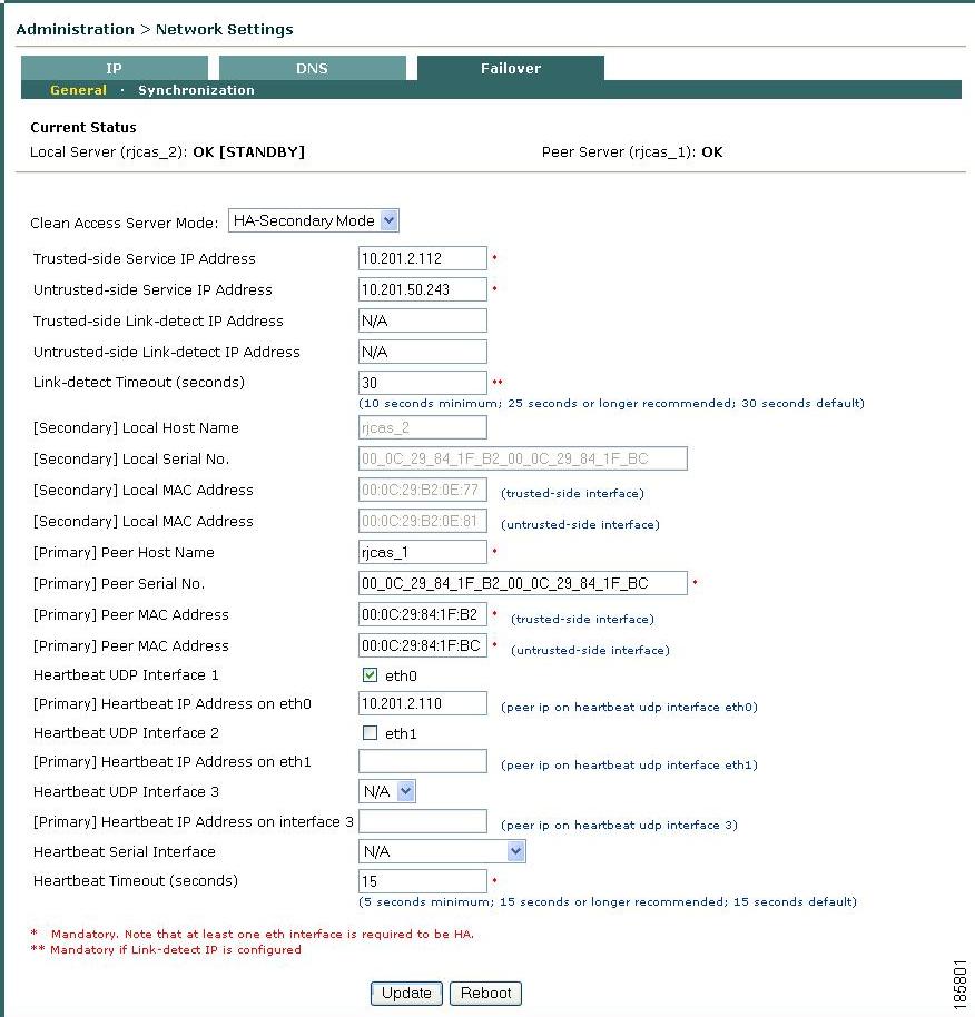
5.
Figure 4-16 Failover —HA-Secondary Mode
6.
–
–
•
•
Note
•
Note
See Choosing External IPs for Link-Based Failover for additional details.•
•
•
•
Note
•
•
•
•
•
•
•
•
•
•
Note
•
Note
Note
•
Note
Another method you can use to avoid this scenario is to ensure you use an additional Ethernet interface link (eth2, eth3) for heartbeat monitoring between your CAS Ha pair nodes. See Heartbeat UDP Interface 2 and Heartbeat UDP interface 3, above and Configuring Additional NIC Cards, for more information.•
•
d. Configure the SSL Certificate
7.
If using a temporary certificate for the HA pair:
a.
b.
c.
If using a CA-signed certificate for the HA pair:
a.
b.
c.
For more information, see the "Manage CAS SSL Certificates" section in the Cisco NAC Appliance - Clean Access Server Configuration Guide, Release 4.9(2).
e. Reboot the HA-Secondary CAS
8.
Connect the Clean Access Servers and Complete the Configuration
1.
2.
3.
Figure 4-17 Active CAS in an HA-Pair
4.
5.
Failing Over an HA-CAS Pair
To test your HA system, use the following steps:
1.
2.
3.
4.
Note
5.
6.
7.
"rjcas_1 is dead. rjcas_2 is up").8.
Modifying CAS High Availability Settings
The following instructions describe how to change settings for an existing high-availability Clean Access Server pair. Changing the Service IP, the subnet mask, or the default gateway for a high-availability pair requires updating the Clean Access Manager and rebooting the Clean Access Server.
Additionally, if the Service IP address is changed and the SSL certificate for the Clean Access Server is based on the Service IP, a new certificate must be generated and imported to each Clean Access Server in the high-availability pair. If the SSL certificate is based on the host name of the Clean Access Server, generating a new certificate is not necessary. However, make sure to change the IP address for that host name in your DNS server.
The general sequence of steps is as follows:
1.
2.
3.
4.
5.
To Change IP Settings for an HA-CAS
1.
2.
3.
4.
5.
Caution
6.
7.
8.
https://<primary_CAS_eth0_IP_address>/admin9.
10.
11.
–
–
–
–
–
–
12.
13.
14.
15.
Upgrading an Existing Failover Pair
For instructions on upgrading an existing failover pair to a new Cisco NAC Appliance release, see "Upgrading High Availability Pairs" in the corresponding Release Notes for Cisco NAC Appliance.
Configuring High Availability for Virtual Gateway Mode
You can follow the same instructions explained in CAM High Availability Overview and CAS High Availability Overview for Virtual Gateway Mode.
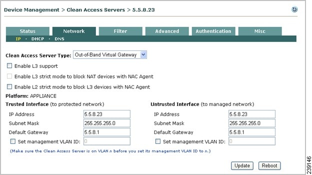
The difference is, if you have deployed your CASs in Virtual Gateway mode, the Trusted and Untrusted interfaces have the same IP address as shown in Figure 4-18.
Figure 4-18 Clean Access Server - Network Settings
WarningAfter HA configuration is complete on both CASs, use the Service IP in the New Server form to add the HA-CAS pair to the CAM. Note that the HA-CAS pair is automatically added as the same Server Type. For example, Out-of-Band Virtual Gateway, as shown in Figure 4-19.
Figure 4-19
HA-Pair with Virtual Gateway
Useful CLI Commands for HA
Clean Access Manager
The following are useful files to know about for HA on the CAM:
•
•
The following example shows the location of the HA debug/log files, as well as the name of each CAM (node) in the HA pair:
[root@rjcam_1 ha.d]# more ha.cf# Generated by make-hacf.pludpport 694bcast eth1auto_failback offapiauth default uid=rootlog_badpack falsedebug 0debugfile /var/log/ha-debuglogfile /var/log/ha-log#logfacility local0watchdog /dev/watchdogkeepalive 2warntime 10deadtime 15node rjcam_1node rjcam_2Verifying Active/Standby Runtime Status on the HA CAM
The following example shows how to use the CLI to determine the runtime status (active or standby) of each CAM in the HA pair. You can run the fostate.sh command from the /perfigo/common/bin/ directory on new and upgraded CAMs.
1.
[root@rjcam_1 ~]# ./fostate.shMy node is active, peer node is standby[root@rjcam_1 ~]#This CAM is the active CAM in the HA-pair.
2.
[root@rjcam_2 ~]# ./fostate.shMy node is standby, peer node is active[root@rjcam_2 ~]#This CAM is the standby CAM in the HA-pair.
Clean Access Server
The following are useful files to know about for HA on the CAS:
•
•
•
•
HA CAS Configuration Status
The /etc/ha.d/perfigo.conf file shows a variety of configuration information for an HA-CAS, including hostname (rjcas_1), peer hostname (rjcas_2), HA mode (Primary), heartbeat interface (UDP/serial), and Link-detect interface information:
[root@rjcas_1 ha.d]# more perfigo.conf#linux-ha#Mon Aug 28 18:50:15 PDT 2006WIRELESS_SERVICEIP=10.10.20.4PING_DEAD=25HOSTNAME=rjcas_1HA_DEAD=15PEERGUSSK=PEERMAC=00\:16\:35\:BF\:FE\:67PEERHOSTNAME=rjcas_2TRUSTED_PINGNODE=10.10.40.100UNTRUSTED_PINGNODE=10.10.20.100HAMODE=PRIMARYPEERMAC0=00\:16\:35\:BF\:FE\:66PEERHOSTIP=10.10.50.2HA_FAILBACK=offHA_UDP=eth2WIRED_SERVICEIP=10.10.20.4HA_SERIAL=ttyS0Heartbeat/Link-Based Connections
The /etc/ha.d/ha.cf file shows additional information about the heartbeat and link-based connections:
[root@rjcas_1 ha.d]# more ha.cf# Generated by make-hacf-ss.pludpport 694ucast eth2 10.10.50.2baud 19200serial /dev/ttyS0keepalive 2deadtime 15deadping 25auto_failback offapiauth default uid=rootrespawn hacluster /usr/lib64/heartbeat/ipfailping 10.10.20.100ping 10.10.40.100log_badpack falsewarntime 10debug 0debugfile /var/log/ha-debuglogfile /var/log/ha-logwatchdog /dev/watchdognode rjcas_1node rjcas_2Link-Detect Interfaces
The /etc/ha.d/linkdetect.conf file is useful if your network topology restricts configuring external (pingable) interfaces for Link-detect functionality between your CAS HA pair appliances. This file specifies the CAS network interfaces (eth0, eth1, or both) to monitor for Link-detect functionality. If a monitored interface loses connectivity with its associated external interface, the active CAS fails over and the standby CAS assumes the active role.
To create and/or update the linkdetect.conf file in the CAS:
Step 1
Step 2
Step 3
Step 4
[root@rjcas_1 ha.d]# more linkdetect.conf# The following network interfaces will be monitored for link healthiness# The active CAS will change to standby mode when any link failure is detected#eth0eth1Step 5
In the above linkdetect.conf file example, both the eth0 and eth1 interfaces on the CAS are monitored for network connectivity.
Note
Active/Standby Status
The following example shows how to use the CLI to determine the runtime status (active or standby) of each CAS in the HA pair. You can find the fostate.sh command in the /perfigo/common/bin/ directory on new and upgraded CASs.
1.
https://, and run the fostate.sh script on the first CAS:[root@rjcas_1 bin]# ./fostate.shMy node is active, peer node is standby[root@rjcas_1 bin]#This CAS is the active CAS in the HA-pair.
2.
[root@rjcas_2 bin]# ./fostate.shMy node is standby, peer node is active[root@rjcas_2 bin]#This CAS is the standby CAS in the HA-pair.
Accessing High Availability Pair CAS Web Consoles
Determining Active and Standby CAS
From the CAM web console, go to Device Management > CCA Servers > List of Servers to view your HA-CAS pairs. The List of Servers page displays the Service IP of the CAS pair first, followed by the IP address of the Active CAS in brackets. When a secondary CAS takes over, its IP address will be listed in the brackets as the Active server.
Note
Determining Primary and Secondary CAS
Open the direct access console for each CAS in the pair by typing the following in the URL/Address field of a web browser (you should have two browsers open):
•
/perfigo/common/bin/.•
https://172.16.1.2/admin.In each CAS web console, go to Administration > Network Settings > Failover > General.
•
•
For releases prior to 4.0(0), the Secondary CAS is labelled as HA-Standby Mode (CAS) for the initial HA configuration.