-
Cisco NAC Appliance - Clean Access Server Installation and Configuration Guide, Release 4.6(1)
-
About This Guide
-
Introduction
-
Planning Your Deployment
-
Configuring Layer 3 Out-of-Band
-
Installing the Clean Access Server NAC Appliance
-
Configuring the CAS Managed Network
-
Configuring DHCP
-
Integrating with Cisco VPN Concentrators
-
Local Traffic Control Policies
-
Configuring Active Directory Single Sign-On
-
Local Authentication Settings
-
Local Certified and Floating Devices
-
Administering the CAS
-
Configuring High Availability
-
Open Source License Acknowledgements
-
Index
-
Table Of Contents
Installing the Clean Access Server
Cisco NAC Appliance Hardware Platforms
Virtual Gateway Mode Connection Requirements
Switch Support for CAS Virtual Gateway/VLAN Mapping (IB and OOB)
Determining VLANs For Virtual Gateway
Summary of Steps For New Installation
Connect the Clean Access Server
Configuring Boot Settings on NAC-3310 Based Appliances
Install the Clean Access Server Software from CD-ROM
Perform the Initial Configuration
Important Notes for SSL Certificates
CAS CLI Commands for Cisco NAC Appliance
CAS CLI Commands for Cisco NAC Profiler
CAM/CAS Connectivity Across a Firewall
Configuring the CAS Behind a NAT Firewall
Configuring Additional NIC Cards
Troubleshooting the Installation
Network Interface Card (NIC) Driver Not Supported
Resetting the Clean Access Server Configuration
Installing the Clean Access Server
Note
The installation example and references in this chapter focus on Cisco NAC 3300 Series appliances. For Cisco NAC network module installation information, refer to Getting Started with Cisco NAC Network Modules in Cisco Access Routers and Installing Cisco Network Modules in Cisco Access Routers.
This chapter describes how to install and initially configure the Clean Access Server (CAS). Topics include:
•
•
•
•
•
•
•
•
•
Overview
When you receive a new Cisco NAC Appliance, you will need to connect to the appliance and perform initial configuration. If you want to install a different version of the software than what is shipped on the appliance, you can perform software installation via CD first. Refer to Supported Hardware and System Requirements for Cisco NAC Appliance (Cisco Clean Access) for details on the software versions supported on Cisco NAC Appliance 3300 Series platforms.
This chapter contains information for performing CD software installation and initial configuration of a Clean Access Server. With Cisco NAC Appliance software installation via CD, you must select whether to install the Clean Access Manager or Clean Access Server application. Once the CAM or CAS is installed on the appliance (application, OS, and relevant components), the installation of any other packages or applications on the CAM or CAS is not supported.
Note
Cisco NAC Appliance Hardware Platforms
The Cisco NAC Appliance 3300 Series hardware platforms are Linux-based network hardware appliances which are pre-installed with either the CAM (MANAGER) or CAS (SERVER) application, the operating system, and all relevant components on a dedicated CAS machine. The operating system comprises a hardened Linux kernel based on a Fedora core. Cisco NAC Appliance does not support the installation of any other packages or applications onto a CAM or CAS dedicated machine.
Starting from Cisco NAC Appliance Release 4.5, Cisco NAC Appliance software only supports and can only be installed on the following Cisco NAC Appliance platforms:
•
•
•
•
•
Note
The Cisco NAC Appliance 3300 Series provides Linux-based network hardware appliances which are pre-installed with either the CAM (MANAGER) or CAS (SERVER) application, the operating system and all relevant components on a dedicated server machine.
The Cisco NAC network module is a CAS you can install in a Cisco 2800 and 3800 Series ISR chassis that features all of the same features and functionality as a stand-alone CAS appliance with one exception; the Cisco NAC network module does not support high availability.
Note
The Cisco NAC Appliance operating system is comprised of a hardened Linux kernel based on a Fedora core. Cisco NAC Appliance does not support the installation of any other packages or applications onto a CAM or CAS dedicated machine.
Note
Refer the Cisco NAC Appliance Hardware Installation Quick Start Guide, Release 4.5 for further details on the Cisco NAC Appliance 3300 Series appliances.
Switch/Router Configuration
The Clean Access Server does not advertise routes. Instead, static routes must be added to the next hop router indicating that traffic to the managed subnets must be relayed to the Clean Access Server's trusted interface.
When the Clean Access Server is in Real-IP Gateway mode, it can act as a DHCP Server or DHCP Relay. With DHCP functionality enabled, the CAS provides the appropriate gateway information (that is, the CAS's untrusted interface IP address) to the clients. If the CAS is working as a DHCP Relay, then the DHCP server in your network must be configured to provide the managed clients with the appropriate gateway information (that is, the Clean Access Server's untrusted interface IP address).
Virtual Gateway Mode Connection Requirements
For all deployments, if planning to configure the Clean Access Server in Virtual Gateway mode (IB or OOB), do not connect the untrusted interface (eth1) of the standalone CAS or HA-Primary CAS until after you have added the CAS to the CAM from the web admin console. For Virtual Gateway HA-CAS pairs, also do not connect the eth1 interface of the HA-Secondary CAS until after HA configuration is fully complete. Keeping the eth1 interface connected while performing initial installation and configuration of the CAS for Virtual Gateway mode can result in network connectivity issues.
When setting up a CAS in Virtual Gateway mode, you specify the same IP address for the trusted (eth0) and untrusted (eth1) network interfaces during the initial installation of the CAS via CLI. At this point in the installation, the CAS does not recognize that it is a Virtual Gateway. It will attempt to connect to the network using both interfaces, causing collisions and possible port disabling by the switch. Disconnecting the untrusted interface until after adding the CAS to the CAM in Virtual Gateway mode prevents these connectivity issues. Once the CAS has been added to the CAM in Virtual Gateway mode, you can reconnect the untrusted interface.
Administrators must use the following procedure for correct configuration of a Virtual Gateway Central Deployment. To prevent looping on any central/core switch as you plug both interfaces of the Clean Access Server into the switch, perform the following steps:
Step 1
Step 2
Step 3
Step 4
Step 5
a.
b.
Note
Step 6
Note
Step 7
Step 8
Switch Support for CAS Virtual Gateway/VLAN Mapping (IB and OOB)
For details on Cisco Catalyst switch model/NME support for the Virtual Gateway VLAN Mapping feature of the Clean Access Server for either in-band (IB) or out-of-band (OOB) deployments, refer to Switch Support for Cisco NAC Appliance.
Determining VLANs For Virtual Gateway
Before you start the initial installation for a Clean Access Server Virtual Gateway deployment, ensure that following is in place for your deployment:
•
•
•
–
–
•
•
•
•
•
See Understanding VLAN Settings, page 5-33 and VLAN Mapping in Virtual Gateway Modes, page 5-35 for additional details.
Summary of Steps For New Installation
Note
Step 1
Note
Step 2
Note
Note
Step 3
Step 4
Step 5
Note
Step 6
Note
You must use identical appliances (e.g. NAC-3350 and NAC-3350) in order to configure High Availability (HA) pairs of Clean Access Managers (CAMs) or Clean Access Servers (CASs).Step 7
Step 8
Connect the Clean Access Server
To install the Clean Access Server software from CD-ROM or to perform its initial configuration, you will need to connect the target machine and access the CAS command line interface.
Step 1
Warning
If needed, refer to "Cisco NAC Appliance Hardware Summary" in the Cisco NAC Appliance Hardware Installation Quick Start Guide, or the documentation that came with your CAS to find the serial and Ethernet connectors.
Step 2
Step 3
Step 4
a.
b.
Note
Serial Connection to the CAS
This section details how to access the CAS command line via serial connection.
Step 1
Note
Step 2
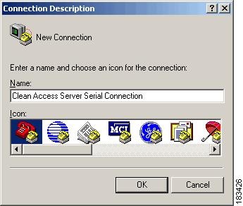
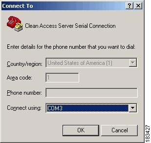
Setting Up the HyperTerminal Connection
Step 3
Step 4
Step 5
Step 6
•
•
•
•
•
Step 7
Step 8
•
•
Note
Configuring Boot Settings on NAC-3310 Based Appliances
If your NAC-3310 appliance does not read the software on the CD ROM drive, and instead attempts to boot from the hard disk, use the following steps to configure the appliance to boot from CD ROM before attempting to re-image or upgrade the appliance from CD.
Step 1
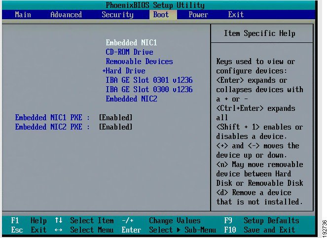
Step 2
Figure 4-1 Boot Menu
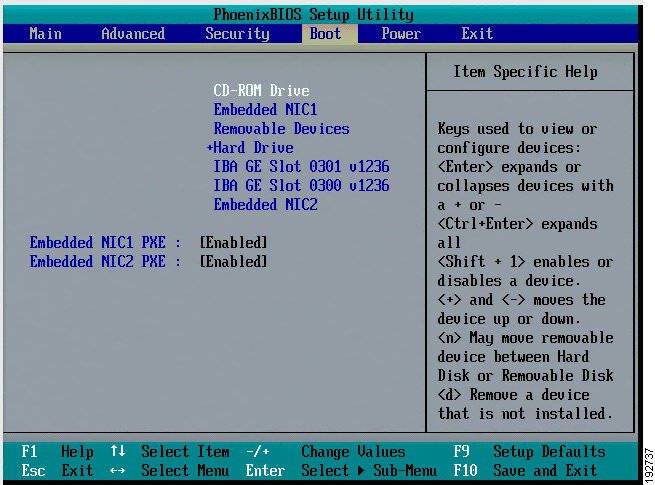
Step 3
Figure 4-2 Boot from CD-ROM Drive
Step 4
Install the Clean Access Server Software from CD-ROM
Once you are connected to the command line of the CAS (as described in Connect the Clean Access Server) use the following steps to install the Clean Access Server software from CD-ROM.
Caution
CD Installation Steps
The entire installation process, including the configuration steps described in Perform the Initial Configuration should take about 15 minutes.
Step 1
Step 2
Cisco Clean Access 4.6-1 Installer (C) 2009 Cisco Systems, Inc.Welcome to the Cisco Clean Access 4.6-1 Installer!- To install a Cisco Clean Access device, press the <ENTER> key.- To install a Cisco Clean Access device over a serial console, enter serial at the boot prompt and press the <ENTER> key.boot:
Note
Step 3
•
•
Step 4
Checking for existing installations.Clean Access Server 4.1.2.1 installation detected.Please choose one of the following actions:1) Install.2) Exit.Step 5
Please choose one of the following configurations:1) CCA Manager.2) CCA Server.
Caution
Step 6
Installation complete. Press <ENTER> to continueWhen finished, the welcome screen for the Clean Access Server quick configuration utility appears, and a series of questions prompt you for the initial CAS configuration, as described in the next section, Configuration Utility Script.
Note
Perform the Initial Configuration
When installing the Clean Access Server from CD-ROM, the Configuration Utility Script automatically appears after software package installation to prompt you for the initial CAS configuration.
Note
1.
2.
service perfigo configYou can run the service perfigo config command to modify the configuration of the CAS if it cannot be reached through the web admin console. For further details on CLI commands, see CAS CLI Commands.
Configuration Utility Script
Step 1
Step 2
Welcome to the Cisco Clean Access Server quick configuration utility.Note that you need to be root to execute this utility.The utility will now ask you a series of configuration questions.Please answer them carefully.Cisco Clean Access Server, (C) 2009 Cisco Systems, Inc.Step 3
Configuring the network interfaces:Please enter the IP address for the interface eth0 []: 10.201.1.20You entered 10.201.1.20 Is this correct? (y/n)? [y]At the prompt, type the eth0 IP address of the CAS and press Enter. Note that the eth0 IP address of the CAS is the same as the Management IP address. At the confirmation prompt, type y to accept the entry or type n to change it and enter another address for the trusted eth0 network interface. When prompted, press Enter to confirm the value.
Step 4
Please enter the netmask for the interface eth0 []: 255.255.255.0You entered 255.255.255.0, is this correct? (y/n)? [y]Step 5
Please enter the IP address for the default gateway []: 10.201.1.1You entered 10.201.1.1 Is this correct? (y/n)? [y]Step 6
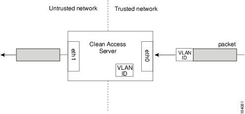
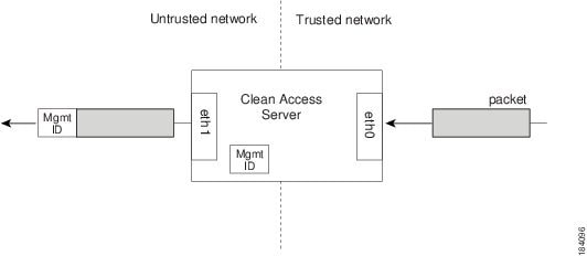
[Vlan Id Passthrough] for packets from eth0 to eth1 is disabled.Would you like to enable it? (y/n)? [n]
Note
•
By default, the VLAN ID is not passed through, that is, the VLAN ID is stripped from packets passed through the CAS, as illustrated in Figure 4-3. The IDs are retained by the Clean Access Server and attached to response messages passed from the untrusted network back to the trusted network.
Figure 4-3 VLAN ID Termination
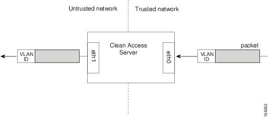
In VLAN ID passthrough, the identifier is retained on traffic that passes through the interface.
Figure 4-4 VLAN ID Passthrough
Step 7
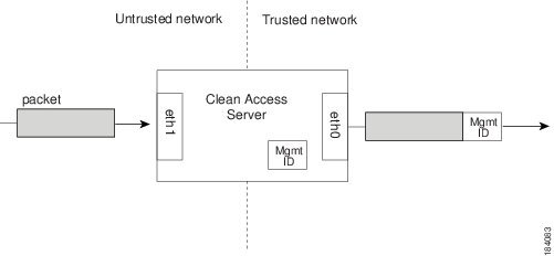
[Management Vlan Tagging] for egress packets of eth0 is disabled.Would you like to enable it? (y/n)? [n]
Note
A Management VLAN identifier is a default VLAN identifier that is added to a packet if it does not have its own VLAN identifier or if the identifier was originally stripped by the adjacent interface. The setting at the prompt applies to traffic passing from the untrusted network to the trusted network.
Figure 4-5 Eth0 Egress Packets with Management VLAN ID Tagging
Note
•
Step 8
Please enter the IP address for the untrusted interface eth1 []: 192.168.10.10You entered 192.168.10.10 Is this correct? (y/n)? [y]Step 9
Please enter the netmask for the interface eth1 []: 255.255.255.0You entered 255.255.255.0, is this correct? (y/n)? [y]Step 10
•
•
Please enter the IP address for the default gateway []: 192.168.10.1You entered 192.168.10.1 Is this correct? (y/n)? [y]Step 11
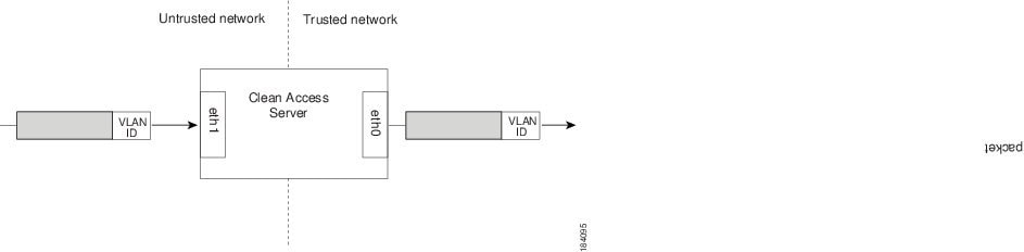
[Vlan Id Passthrough] for packets from eth1 to eth0 is disabled.Would you like to enable it? (y/n)? [n]Figure 4-6 VLAN ID Passthrough
Step 12
[Management Vlan Tagging] for egress packets of eth1 is disabled.Would you like to enable it? (y/n)? [n]
Note
Figure 4-7 Eth1 Egress Packets with Management VLAN ID Tagging
Step 13
Please enter the hostname [nacserver]: cas1You entered cas1 Is this correct? (y/n)? [y]Step 14
Please enter the IP address for the name server: []: 172.10.16.16You entered 172.10.16.16 Is this correct? (y/n)? [y]Step 15
The shared secret used between Clean Access Manager and Clean Access Server is the default
string: cisco123
This is highly insecure. It is recommended that you choose a string that is unique to your installation.Please remember to configure all Clean Access Devices with the same string.Only the first 8 characters supplied will be used.Please enter the shared secret between Clean Access Server and Clean Access Manager:
Caution
Step 16
a.
>>> Configuring date and time:The timezone is currently not set on this system.Please identify a location so that time zone rules can be set correctly.Please select a continent or ocean.1) Africa2) Americas3) Antarctica4) Arctic Ocean5) Asia6) Atlantic Ocean7) Australia8) Europe9) Indian Ocean10) Pacific Ocean11) none - I want to specify the time zone using the Posix TZ format.#? 2b.
Please select a country.1) Anguilla 18) Ecuador 35) Paraguay2) Antigua & Barbuda 19) El Salvador 36) Peru3) Argentina 20) French Guiana 37) Puerto Rico4) Aruba 21) Greenland 38) St Kitts & Nevis5) Bahamas 22) Grenada 39) St Lucia6) Barbados 23) Guadeloupe 40) St Pierre & Miquelon7) Belize 24) Guatemala 41) St Vincent8) Bolivia 25) Guyana 42) Suriname9) Brazil 26) Haiti 43) Trinidad & Tobago10) Canada 27) Honduras 44) Turks & Caicos Is11) Cayman Islands 28) Jamaica 45) United States12) Chile 29) Martinique 46) Uruguay13) Colombia 30) Mexico 47) Venezuela14) Costa Rica 31) Montserrat 48) Virgin Islands (UK)15) Cuba 32) Netherlands Antilles 49) Virgin Islands (US)16) Dominica 33) Nicaragua17) Dominican Republic 34) Panamac.
Please select one of the following time zone regions.1) Eastern Time2) Eastern Time - Michigan - most locations3) Eastern Time - Kentucky - Louisville area4) Eastern Time - Kentucky - Wayne County5) Eastern Time - Indiana - most locations6) Eastern Time - Indiana - Crawford County7) Eastern Time - Indiana - Starke County8) Eastern Time - Indiana - Switzerland County9) Central Time10) Central Time - Indiana - Daviess, Dubois, Knox, Martin, Perry & Pulaski Counties11) Central Time - Indiana - Pike County12) Central Time - Michigan - Dickinson, Gogebic, Iron & Menominee Counties13) Central Time - North Dakota - Oliver County14) Central Time - North Dakota - Morton County (except Mandan area)15) Mountain Time16) Mountain Time - south Idaho & east Oregon17) Mountain Time - Navajo18) Mountain Standard Time - Arizona19) Pacific Time20) Alaska Time21) Alaska Time - Alaska panhandle22) Alaska Time - Alaska panhandle neck23) Alaska Time - west Alaska24) Aleutian Islands25) Hawaiid.
The following information has been given:United StatesPacific TimeIs the above information OK?1) Yes2) NoStep 17
Current date and time hh:mm:ss mm/dd/yy [11:23:33 08/22/08]: 11:23:33 08/22/08You entered 11:23:33 08/22/08 Is this correct? (y/n)? [y]Step 18
a.
Note
b.
c.
d.
e.
f.
g.
You entered the following:Domain: mydomain.comOrganization unit: testOrganization name: accessCity name: My TownState code: CACountry code: USIs this correct? (y/n)? [y]When you confirm your values, the certificate is generated and the Clean Access Server database is initialized.
Step 19
Enable Prelogin Banner Support? (y/n)? [n]For more information and an example of the Pre-login Banner feature, see Figure 12-2 on page 12-3.
Step 20
Cisco NAC Appliance supports using Strong Passwords for root user login. Passwords must be at least 8 characters long and feature a combination of upper- and lower-case letters, digits, and other characters. For example, the password 10-9=One would not satisfy the requirements because it does not feature two characters from each category, but 1o-9=OnE is a valid password. For more details, see the "Manage System Passwords" section in the "Administer the CAM" chapter in the Cisco NAC Appliance - Clean Access Manager Installation and Configuration Guide, Release 4.6(1).
For security reasons, it is highly recommended that you change the password for the root
user.
** Please enter a valid password for root user as per the requirements below! **Changing password for user root.You can now choose the new password.A valid password should be a mix of upper and lower case letters,digits, and other characters. Minimum of 8 characters and maximumof 16 characters with characters from all of these classes. Minimumof 2 characters from each of the four character classes is mandatory.An upper case letter that begins the password and a digit that endsit do not count towards the number of character classes used.Enter new password:Re-type new password:passwd: all authentication tokens updated successfully.Step 21
Please enter an appropriately secure password for the web console admin user.New password for web console admin:Confirm new password for web console admin:Step 22
Configuration is complete.Changes require a REBOOT of Clean Access Server.Step 23
# rebootStep 24
Important Notes for SSL Certificates
•
•
–
–
For details on CAM certificates, see the Cisco NAC Appliance - Clean Access Manager Installation and Configuration Guide, Release 4.6(1).
•
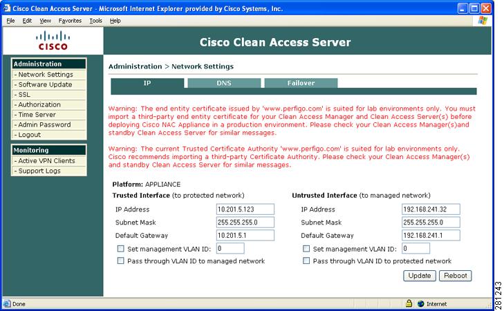
Note
Figure 4-8 Administrator Web Console Messages Warning to Obtain Trusted Certificate Authority and Remove Existing "www.perfigo.com" Certificate
CAS CLI Commands
The CAM web admin console allows you to perform most of the tasks required for administering Cisco NAC Appliance deployment. However, there are two cases where the command line interface of the CAS can be or must be used:
•
•
To run the CLI commands, access the CAS using SSH and log in as user root and enter the root user password. If already serially connected to the CAS, you can run CLI commands from the terminal emulation console after logging in as root (see Install the Clean Access Server Software from CD-ROM).
CAS CLI Commands for Cisco NAC Appliance
The format service perfigo <command> is used to enter a command from the command line. Table 4-1 lists the commonly used Cisco NAC Appliance CLI commands.
Table 4-1 Cisco NAC Appliance CLI Commands for CAS
service perfigo startStarts up the CAS. If the CAS is already running, a warning message appears. The CAS must be stopped for this command to be used.
service perfigo stopShuts down the Cisco NAC Appliance service.
Note
service perfigo maintenanceThis command brings the CAS to maintenance mode, in which only the basic CAS router runs and continues to handle VLAN-tagged packets. The command allows communication through the management VLAN and is intended for environments where the CAS is in trunk mode and the native VLAN is different than the management VLAN.
Note
service perfigo platformThis command allows you to determine whether the CAS is a standard Clean Access Server appliance or a Cisco NAC network module installed in a Cisco ISR router chassis. The output displays either "APPLIANCE" or "NME-NAC" as the platform setting.
For detailed installation and configuration information, see Getting Started with Cisco NAC Network Modules in Cisco Access Routers and Installing Cisco Network Modules in Cisco Access Routers.
service perfigo restartShuts down the Cisco NAC Appliance service and starts it up again. This is used when the service is already running and you want to restart it.
Note
service perfigo rebootShuts down and reboots the machine. You can also use the Linux reboot command.
service perfigo configStarts the configuration script to modify the CAS configuration. After completing service perfigo config, you must reboot the CAS. For instructions on using the script, see Perform the Initial Configuration
service perfigo timeUse to modify the time zone settings.
CAS CLI Commands for Cisco NAC Profiler
The Clean Access Server is shipped with a default version of the Cisco NAC Profiler Collector component, which needs to be enabled and configured separately when integrating with the Cisco NAC Profiler solution. Table 4-2 lists CLI commands issued on the CAS for the Cisco NAC Profiler Collector service. For complete details on the Cisco NAC Profiler solution, refer to the Cisco NAC Profiler Installation and Configuration Guide and Release Notes for Cisco NAC Profiler.
Note
Table 4-2 Cisco NAC Profiler Collector CLI Commands for CAS
service collector start
Starts the Collector service on the CAS.
service collector stop
Shuts down the Collector service on the CAS.
service collector verify
Displays the configured Collector Services running on the CAS
Collector Network ConfigurationCollector Name = bcas1-fwConnection Type = serverListen on IP = 10.40.1.10Network IP ACL127.0.0.110.10.0.21110.10.0.21010.10.0.212Port Number = 31416Encryption type = AESShared secret = profilerservice collector status
Displays the running status of the individual Collector modules on the CAS, for example:
Profiler Statuso Server Not Installedo Forwarder Runningo NetMap Runningo NetTrap Runningo NetWatch Runningo NetInquiry Runningo NetRelay Runningservice collector restart
Stops and then restarts the Collector service on the CAS. This is used when the service is already running and you want to restart it.
service collector config
Starts the Collector service configuration script to allow communication with the Cisco NAC Profiler Server. For example:
[root@caserver12 /]# service collector configEnable the NAC Collector (y/n) [y]:Configure NAC Collector (y/n) [y]:Network configuration to connect to a NAC Profiler ServerConnection type (server/client) [client]:Connect to IP [127.0.0.1]: 192.168.96.20Port number [31416]:Encryption type (AES, blowfish, none) [AES]: noneShared secret []: cisco1232-- Configured caserver12-fw-- Configured caserver12-nm-- Configured caserver12-nt-- Configured caserver12-nw-- Configured caserver12-ni-- Configured caserver12-nrNAC Collector has been configuredFor detailed installation and configuration information, see the Cisco NAC Profiler Installation and Configuration Guide.
CAM/CAS Connectivity Across a Firewall
See the Cisco NAC Appliance - Clean Access Manager Installation and Configuration Guide, Release 4.6(1) for details on which ports to open in a firewall to allow communication between the Clean Access Manager and Clean Access Server(s).
Configuring the CAS Behind a NAT Firewall
Caution
If deploying the Clean Access Server behind a firewall (there is a NAT router between CAS and CAM), you will need to perform the following steps to make the CAS accessible:
Step 1
Step 2
Step 3
Step 4
Step 5
CATALINA_OPTS="-server -Xms64m -Xmx${MAX}m -Xincgc -Djava.util.logging.config.file=${CATALINA_HOME}/conf/redirect-log.properties -Dperfigo.jmx.context=${PERFIGO_SECRET} -Djava.security.auth.login.config=${CATALINA_HOME}/conf/sso-login.conf -Dsun.net.inetaddr.ttl=60 -Dsun.net.inetaddr.negative.ttl=10 -Djava.security.egd=file:/dev/urandom"-Djava.rmi.server.hostname=caserver1"Step 6
Step 7
Step 8
Step 9
Step 10
<public_IP_address> <caserver1_hostname> <caserver2_hostname>where:
•
•
The Clean Access Server(s) should now be addressable behind the firewall.
Configuring Additional NIC Cards
The Configuration Utility script assumes that the CAM and CAS machines come with eth0 (NIC1) and eth1 (NIC2) interfaces by default and allows you to configure these during initial installation. If your system has additional network interface cards (e.g. NIC3, NIC4), you can use the following instructions to configure the additional interfaces (e.g. eth2, eth3) on those cards. Typically, eth2 needs to be configured when setting up Clean Access Server systems for High Availability. For HA, once the eth2 (NIC3) interface is configured with the proper addressing, it can then be configured as the dedicated UDP heartbeat interface for the HA-CAS.
Note
•
•
To Configure an Additional NIC
Step 1
ifconfig eth2
Step 2
Step 3
cd /etc/sysconfig/network-scripts
Step 4
vi ifcfg-eth2Step 5
DEVICE=eth2IPADDR=192.168.0.253NETMASK=255.255.255.252BROADCAST=192.168.0.255NETWORK=192.168.0.252BOOTPROTO=staticONBOOT=yesTYPE=EthernetStep 6
Step 7
Note
Troubleshooting the Installation
Note
Network Interface Card (NIC) Driver Not Supported
For complete details, refer to the "Troubleshooting Network Card Driver Support Issues" section of the Supported Hardware and System Requirements for Cisco NAC Appliance (Cisco Clean Access).
Resetting the Clean Access Server Configuration
If incorrect network, shared secret, or VLAN settings have rendered the Clean Access Server unreachable from the Clean Access Manager, you can reset the Clean Access Server's configuration. Note that resetting the configuration restores the Clean Access Server configuration to its install state. Any configuration settings made since installation will be lost.
To reset the configuration:
Step 1
Step 2
# rm /perfigo/access/bin/env
Step 3
# service perfigo reboot
You can now add the CAS to the CAM. See Chapter 5, "Configuring the CAS Managed Network."