[an error occurred while processing this directive]

Support

Installing the IPS 4345 and IPS 4360

 Feedback

Table Of Contents

Installing the IPS 4345 and IPS 4360

Contents

Installation Notes and Caveats

Product Overview

Specifications

Accessories Kit

Front and Back Panel Features

Installing the Appliance on the Network

Rack Mounting the Appliance

Installing and Removing the Power Supply in the IPS 4360


Installing the IPS 4345 and IPS 4360


Contents

This chapter describes the Cisco IPS 4345 and the IPS 4360, and includes the following sections:

Installation Notes and Caveats

Product Overview

Specifications

Accessories Kit

Front and Back Panel Features

Installing the Appliance on the Network

Rack Mounting the Appliance

Installing and Removing the Power Supply in the IPS 4360

Installation Notes and Caveats


Note Read through the entire guide before beginning any of the installation procedures.


Warning Only trained and qualified personnel should install, replace, or service this equipment. Statement 49

Caution Read the safety warnings in the Regulatory Compliance and Safety Information for the Cisco ASA 5500-X Series Adaptive Security Appliances and the Intrusion Prevention System 4300 Series Appliances document and follow proper safety procedures when performing the steps in this guide.

Product Overview

The IPS 4345 delivers 500 Megabits of intrusion prevention performance. You can use the IPS 4345 to protect both half Gigabit subnets and aggregated traffic traversing switches from multiple subnets. The IPS 4345 is a purpose-built device that has support for both copper and fiber NIC environments thus providing flexibility of deployment in any environment. It replaces the IPS 4240 and the IPS 4255.

The IPS 4360 delivers 1 Gigabit of intrusion prevention performance. You can use the IPS 4360 to protect Gigabit subnets and aggregated traffic traversing switches from multiple subnets. The IPS 4360 is a purpose-built device that has support for both copper and fiber NIC environments thus providing flexibility of deployment in any environment. It replaces the IPS 4260.

All connectivity is on the back of the appliance. The IPS 4345 and the IPS 4360 have eight Gigabit Ethernet network ports. The network port numbers increase from right to left and from bottom to top. There is also a built-in management port, a console interface, and 2 USB ports.

The IPS 4345 monitors 500 Megabits of aggregate network traffic on multiple sensing interfaces and is also inline ready. It supports both copper and fiber interfaces. The 500 Mbps performance is traffic combined from all sensing interfaces. The 500 Mbps performance for the IPS 4345 is based on multiple models of common traffic mixes based on common deployment scenarios while running IPS 7.1.(3)E4 software.

The IPS 4360 monitors greater than 1 Gbps of aggregate network traffic on multiple sensing interfaces and is also inline ready. It supports both copper and fiber interfaces. The 1-Gbps performance is traffic combined from all sensing interfaces. The 1-Gbps performance for the IPS 4360 is based on multiple models of common traffic mixes based on common deployment scenarios while running IPS 7.1.(3)E4 software.


Note The IPS 4345 and IPS 4360 do not currently support hardware bypass.


Specifications

Table 4-1 lists the specifications for the IPS 4345 and the IPS 4360.

Table 4-1 IPS 4345 and IPS 4360 Specifications 

Dimensions and Weight
IPS 4345
IPS 4360

Height

1.67 in (4.2418 cm)

1.67 in (4.2418 cm)

Width

16.7 in (42.418 cm)

16.7 in (42.418 cm)

Depth

15.6 in (39.624 cm)

19.1 in (48.514 cm)

Weight

14.52 lb (6.58616 kg)
with 1 power supply

16.88 lb (7.65663 kg)
with 1 power supply
18.92 (8.58196 kg)
with 2 power supplies

Form factor

1U, 19-inch rack-mountable

1U, 19-inch rack-mountable

Power
   

Power supply

400W

450W

Input current (each input)

4.85A

100V to 120V~/5A
200V to 240V~/2.5A

Leakage current (mA)

3.5mA

3.5mA

Input voltage range

100 to 240~ VAC

100 to 120V/200 to 240V~

Rated input frequency

50 to 60 Hz

50 to 60Hz

Operating power
Steady state/maximum

372W

382W

Total heat dissipation

730 BTU/hr

730 BTU/hr

Output hold-up time

20mS

12mS

Inrush current

40A

40A

Environment
   

Temperature

Operating: 23°F to 49°F
(-5°C to 45°C)
Nonoperating: -13°F to -94°F (-25°C to -70°C)

Operating: 23°F to 49°F
(-5°C to 45°C)
Nonoperating: -13°F to -94°F
(25°C to -70°C)

Airflow

Front to back

Front to back

Relative humidity (noncondensing)

Operating: 0% to 90%
Nonoperating: 10% to 90%

Operating: 0% to 90%
Nonoperating: 10% to 90%

Altitude

Operating: 0 to 10,000 ft
(0 to 3048 m)
Nonoperating: 0 to 15,000 ft
(0 to 4572 m)

Operating: 0 to 10,000 ft
(0 to 3048 m)
Nonoperating: 0 to 15,000 ft
(0 to 4572 m)

Acoustic noise

Operating: 64.2
Nonoperating: 70G,4.22m/s

Operating: 67.9
Nonoperating: 70G,4.22m/s

Shock

50G,2ms

50G,2ms

Vibration

Operating: 0.41Grms,3Hz to 500Hz with spectral break points of 0.0005G2/Hz at 10Hz and 200Hz and 5dB/octave roll-off at each end
Nonoperating: 1.12Grms,3Hz to 500Hz with spectral break points of 0.0065G2/Hz at 10Hz and 100Hz and 5dB/octave roll-off at each end

Operating: 0.41Grms,3Hz to 500Hz with spectral break points of 0.0005G2/Hz at 10Hz and 200Hz and 5dB/octave roll-off at each end.
Nonoperating: 1.12Grms,3Hz to 500Hz with spectral break points of 0.0065G2/Hz at 10Hz and 100Hz and 5dB/octave roll-off at each end


Accessories Kit

The IPS 4345 and IPS 4360 accessories kit contains the following items:

IPS 4345—Documentation, a power cord, a yellow Ethernet cable, 10-32 Phillips screws (4), 12-24 Phillips screws (4), a blue console cable PC terminal adapter, and a power cord retainer.

IPS 4360—Documentation, a power cord, a blue console cable PC terminal adapter, a power cord retainer, and a slide rail kit.

Front and Back Panel Features

This section describes the IPS 4345 and IPS 4360 front and back panel features and indicators.

Front Panel Features

Figure 4-1 shows the front view of the IPS 4345 and IPS 4360.

Figure 4-1 IPS 4345 and IPS 4360 Front Panel View

1

Power button

2

Indicators


Figure 4-2 shows the indicators for the IPS 4345. These indicators are also found on the back panel of the IPS 4345.

Figure 4-2 IPS 4345 Indicators

Figure 4-3 shows the indicators for the IPS 4360. These indicators are also found on the back panel of the IPS 4360.

Figure 4-3 IPS 4360 Indicators

Table 4-2 describes the indicators on the IPS 4345 and IPS 4360.

Table 4-2 IPS 4345 and IPS 4360 Indicators 

Indicator
Description

BOOT

Indicates how the power-up diagnostics are proceeding:

Flashing green—Power-up diagnostics are running or the system is booting.

Green—System has passed power-up diagnostics.

Amber—Power-up diagnostics failed.

ACTIVE

Indicates whether the system is off or on:

Off—No power.

Green—System has power.

PS1

Indicates the state of the power supply module installed on the right when facing the back panel:

Off—No power supply module present or no AC input.

Green—Power supply module present, on, and good.

Amber—Power or fan module off or failed.

PS0

Indicates the state of the power module installed on the left when facing the back panel:

Off—No power supply module present or no AC input.

Green—Power supply module present, on, and good.

Amber—Power or fan module off or failed.

ALARM

Indicates whether a component has failed:

Off—No alarm.

Flashing yellow—Critical alarm.

Major failure of hardware component or software module, temperature over the limit, power out of tolerance, or OIR is ready to remove the module.

HD1

N/A

HD2

N/A


S

Figure 4-4 shows the back panel features.


Note The illustration shows the IPS 4360, which has two removable power supply modules. The IPS 4345 has one built-in power supply module.


Figure 4-4 IPS 4345 and IPS 4360 Back Panel Features

1

Reserved for future use

2

Chassis cover removal screw

3

Management port1

4

Network interface ports2

5

Power supply modules

6

Indicators

7

Serial console port3

8

Reserved for future use

1 The Management 0/0 interface is a GigabitEthernet interface that supports FastEthernet and is designed for management traffic only.

2 GigabitEthernet interfaces from right to left and top to bottom—GigabitEthernet 0/0, 0/1, 0/2, and 0/3 and Gigabitethernet 1/0, 1/1, 1/2, and 1/3.

3 The serial console port uses 9600 baud, 8 data bits, 1 stop bit, and no parity.


Table 4-3 describes the rear MGMT and network interface indicators.

Table 4-3 Management and Network Interface Indicators 

Indicator
 
Description

Left side

Green
Flashing green

Physical activity
Network activity

Right side

Not lit
Green
Amber

10 Mbps
100 Mbps
1000 Mbps


Installing the Appliance on the Network


Warning IMPORTANT SAFETY INSTRUCTIONS

This warning symbol means danger. You are in a situation that could cause bodily injury. Before you work on any equipment, be aware of the hazards involved with electrical circuitry and be familiar with standard practices for preventing accidents. Use the statement number provided at the end of each warning to locate its translation in the translated safety warnings that accompanied this device. Statement 1071

SAVE THESE INSTRUCTIONS

Warning Only trained and qualified personnel should be allowed to install, replace, or service this equipment. Statement 1030

To install the appliance on the network, follow these steps:


Step 1 Position the appliance on the network.

Step 2 Install the appliance in a rack, if you are rack mounting it.

Step 3 Before connecting a computer or terminal to the ports, check to determine the baud rate of the serial port.

The baud rate must match the default baud rate (9600 baud) of the console port of the appliance. Set up the terminal as follows: 9600 baud (default), 8 data bits, no parity, 1 stop bits, and Flow Control (FC) = Hardware.

Step 4 Connect to the management port.

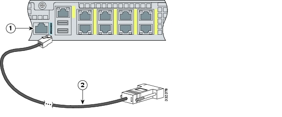
Connect one RJ-45 connector to the management port and connect the other end to the management port on your computer or network device. The appliance has a dedicated management interface referred to as Management 0/0, which is a GigabitEthernet interface with a dedicated port used only for traffic management.

1

Management 0/0 port

2

RJ-45 Ethernet cable


Step 5 Connect to the console port.

The console cable has a DB-9 connector on one end for the serial port on your computer, and the other end is an RJ-45 connector. Connect the RJ-45 connector to the console port on the appliance, and connect the other end of the cable, the DB-9 connector, to the console port on your computer.
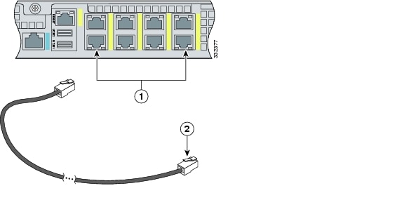
1

RJ-45 console port

2

RJ-45 to DB-9 console cable


Step 6 Connect to the Ethernet ports.

Connect the RJ-45 connector to the Ethernet port and connect the other end of the RJ-45 connector to your network device, such as a router, switch, or hub.

1

RJ-45 Ethernet ports

2

RJ-45 connector


Step 7 Attach the power cable to the appliance and plug the other end in to a power source (a UPS is recommended).

Step 8 Power on the appliance.

Step 9 Initialize the appliance.

Step 10 Install the most recent Cisco IPS software. You are now ready to configure intrusion prevention on the appliance.


Rack Mounting the Appliance

The slide rail mounting system provides a quick, convenient, and secure method for rack mounting the appliance. You can use it for both the IPS 4345 and IPS 4360.


Note The IPS 4360 ships with a slide rail mounting system, but you can also order it and use it for the IPS 4345.


For instructions on how to install the slide rail mounting system, refer to the Hardware Documentation section of Navigating the Cisco ASA Series Documentation found at this URL:

http://www.cisco.com/en/US/docs/security/asa/roadmap/asaroadmap.html

Installing and Removing the Power Supply in the IPS 4360

The IPS 4360 ships with one power supply installed. You can add an additional power supply or you can order it with two power supplies installed. Having two power supplies installed provides a redundant power option. This configuration ensures that if one power supply fails, the other power supply assumes the full load until the failed power supply is replaced. To maintain airflow, an empty bay must be covered or both bays must be populated with power supplies.

If only one power supply is installed, do not remove the power supply unless the appliance has been powered off. Removing the only operational power supply causes an immediate power loss.


Caution If you remove a power supply, replace it immediately to prevent disruption of service.


Caution If the appliance is subjected to environmental overheating, it shuts down and you must manually power cycle the appliance.


Warning This unit has more than one power supply connection; all connections must be removed completely to completely remove power from the unit. Statement 102

Caution For DC power supplies, use an 80 VDC 20A fuse or circuit breaker on the input during installation.

To remove and install the power supply, follow these steps:


Step 1 If you are adding an additional power supply, from the back of the appliance, push the lever on the slot cover to the left to release it, grasp the handle of the slot cover and pull it away from the chassis. Save the slot cover for future use. Continue with Step 3.

Step 2 If you are replacing a power supply, follow these steps:

a. Power off the appliance.

b. From the back panel of the appliance, unplug the power supply cable.

c. Push the lever on the power supply to the left and remove the power supply by grasping the handle and then pulling the power supply away from the chassis. Continue with Step 3.

Step 3 Install the new power supply by aligning it with the power supply bay and pushing it into place until it is seated.

Step 4 Connect the power cable. If you are installing two power supplies for a redundant configuration, plug each one into a power source (we recommend a UPS).

Step 5 Power on the appliance if you powered it off to replace the only power supply.

Step 6 Check the PS0 and PS1 indicators on the front panel to make sure they are green. On the back panel of the appliance, make sure the power supply indicator on the bottom of each installed power supply is green.


[an error occurred while processing this directive]