Table Of Contents
Shelf Controller Gigabit Ethernet Card
Shelf Controller Gigabit Ethernet Card
This chapter describes the shelf controller Gigabit Ethernet card (SCGE) located on the front (SFC) side of the fabric card chassis (FCC). It includes the following sections:
The SCGE card described in this chapter uses a Class 1 laser. The following warnings apply to the SCGE card.
Warning
Class 1 Laser Product. Statement 113
Warning
Note
Cisco Catalyst switches.Throughout this chapter, both versions of the SCGE cards are referred to as SCGE cards, unless otherwise noted.
SCGE Functional Overview
The shelf controller Gigabit Ethernet (SCGE) card is the local system management node for an FCC. It is available in 2-port and 22-port Gigabit Ethernet (GE) interface configurations. The 2-port SCGE card links an FCC to the external Catalyst switch. The 22-port SCGE card features an integrated switch that eliminates the need for the 2-port SCGE card and the external Cisco Catalyst switch. The SCGE card also controls power up, initialization, SFCs, the optical interface module LED (OIM-LED) card, alarms, power supplies, and fans in an FCC. It also includes the 48-V soft-start circuitry for the fan tray.
The SCGE card provides system initialization, debugging, and low-level hardware control for all SFCs in an FCC and other system cards. The card includes front-panel ports and an alphanumeric LED display. It also includes two PC Card (PCMCIA) slots for local storage needs. One PC card is removable and the other one is fixed. Communication within the chassis takes place over a redundant set of backplane Fast Ethernet (FE) links controlled by the SCGE card.
Note
The SCGE card globally:
•
•
•
In active mode, the SCGE:
•
•
•
•
•
•
•
•
In standby mode, the SCGE card:
•
•
•
The FCC holds up to 24 SFCs, 2 SCGE cards, 2 fan trays, 24 optical interface module (OIM) cards, 2 OIM-LED cards, 2 alarm modules, and 2 AC or DC power shelves. Except for the SCGE cards, OIM cards, and fan trays, each of these components has its own service processor (SP) with two backplane FE links to the SCGE cards.
In addition, the two SCGE cards have one FE link between them, and each SCGE card has one backplane FE link routed back to itself. The 48-V soft-start circuit of the fan tray is part of the SCGE card. The SCGE card controls the fan speed and monitors the status of the fan trays through four I2C buses, with two buses going to each fan tray.
2-Port SCGE Card Overview
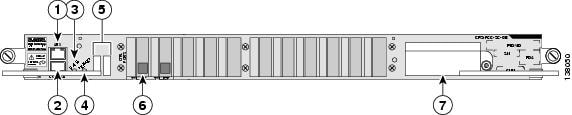
This section describes the 2-port SCGE card (CRS-FCC-SC-GE) and its components. Figure 5-1 shows the front panel of the 2-port SCGE card in a horizontal view.
Figure 5-1 2-Port SCGE Card Front Panel (Horizontal View)
RJ-45 auxiliary (AUX) port
Alphanumeric LEDs
RJ-45 CONSOLE port
Gigabit Ethernet interface
STATUS LED
PCMCIA card slots
PRIMARY LED
Note
Front-Panel Interface
The front panel of the 2-port SCGE card includes various components that interface with the user. This section describes the front-panel interfaces.
Asynchronous Serial Ports
The 2-port SCGE card has two asynchronous serial ports, the CONSOLE and auxiliary (AUX) ports. These ports allow you to connect external serial devices so you can monitor and manage the system. Both ports use RJ-45 receptacles.
•
•
LED Displays
The 2-port SCGE card includes the following LED displays:
•
•
•
–
–
The 2-port SCGE card includes a safety shutdown circuit that powers down all voltages except the 5-V housekeeping voltage. When an abnormal condition is sensed, the STATUS LED on the front panel flashes yellow. Ten seconds later, the shutdown is triggered and power to the card is shut down until the card is reset. After the card powers down, it must be power-cycled by removing it from the chassis or powering down the entire chassis. This mechanism requires that the 5-V housekeeping voltage be functioning correctly.
Gigabit Ethernet Interface
The 2-port SCGE card includes a two-port GE interface (1000BASE-LX) for connection to the control network that links all LCCs and FCCs. See the Cisco CRS-1 Carrier Routing System Multishelf System Interconnection and Cabling Guide for complete multishelf system cabling information.
PCMCIA PC Cards
The 2-port SCGE card includes one removable and one fixed PC Card (PCMCIA Type I / II). The removable, external PC Card facilitates image files of up to 1 gigabyte. The nonremovable, internal PC Card also facilitates image files of up to 1 gigabyte. However, this card is for Cisco use only and is not accessible to users.
22-Port SCGE Card Overview
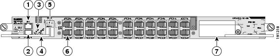
This section describes the 22-port SCGE card (SC-GE-22) and its components. Figure 5-2 shows the front panel of the 22-port SCGE card in a horizontal view.
Figure 5-2 22-Port SCGE Card Front Panel (Horizontal View)
RJ-45 auxiliary (AUX) port
Alphanumeric LEDs
RJ-45 CONSOLE port
Gigabit Ethernet interface
STATUS LED
PCMCIA card slots
PRIMARY LED
Note
Front-Panel Interface
The front panel of the 22-port SCGE card includes various components that interface with the user. This section describes the front-panel interfaces.
Asynchronous Serial Ports
The 22-port SCGE card has two asynchronous serial ports, the CONSOLE and auxiliary (AUX) ports. These ports allow you to connect external serial devices so you can monitor and manage the system. Both ports use RJ-45 receptacles.
•
•
LED Displays
The 22-port SCGE card includes the following LED displays:
•
•
•
–
–
The 22-port SCGE card includes a safety shutdown circuit that powers down all voltages except the 5-V housekeeping voltage. When an abnormal condition is sensed, the STATUS LED on the front panel flashes yellow. Ten seconds later, the shutdown is triggered and power to the card is shut down until the card is reset. After the card powers down, it must be power-cycled by removing it from the chassis or powering down the entire chassis. This mechanism requires that the 5-V housekeeping voltage be functioning correctly.
Gigabit Ethernet Interface
The 22-port SCGE card includes a 22-port GE interface (1000BASE-LX) for connection to the control network that links all LCCs and FCCs. See the Cisco CRS-1 Carrier Routing System Multishelf System Interconnection and Cabling Guide for complete multishelf system cabling information.
PCMCIA PC Cards
The 22-port SCGE card includes one removable and one fixed PC Card (PCMCIA Type I / II). The removable, external PC Card facilitates image files of up to 1 gigabyte. The nonremovable, internal PC Card also facilitates image files of up to 1 gigabyte. However, this card is for Cisco use only and is not accessible to users.