Feedback Feedback
|
Table Of Contents
Cisco AS5850 Universal Gateway
Commissioning GuidelinesInformation About Cisco AS5850 Universal Gateway Commissioning
How to Commission the Cisco AS5850 Universal Gateway
Analyze the System Boot Dialog
Verify the Operating Environment
Inspect the Initial Running Configuration
Explore the Cisco IOS File System
Task 2. Configuring Basic Cisco IOS Software
Configure Host Name, Enable-Secret Password, and Time Stamps
Task 3. Configuring Channelized T1 or E1
Task 4. Configuring Channelized T3
Task 6. Configuring the Serial Interfaces
Task 7. Configuring Ports and Lines
Task 8. Enabling IP Basic Setup
Task 9. Testing Asynchronous EXEC-Shell Connections
Task 10. Configuring GigE Egress
Task 11. Confirming the Final Running Configuration
Cisco Product Security Overview
Reporting Security Problems in Cisco Products
Obtaining Technical Assistance
Cisco Technical Support Website
Definitions of Service Request Severity
Obtaining Additional Publications and Information
Cisco AS5850 Universal Gateway
Commissioning Guidelines
These guidelines detail Cisco AS5850 commissioning, from formal functional setup of the equipment, through systematic software configurations, to initial preparation of the system for data/voice call processing, using local-based authentication.
Use this guide in conjunction with these other Cisco AS5850 documents:
•
Cisco AS5850 Universal Gateway Hardware Installation Guide at http://www.cisco.com/univercd/cc/td/doc/product/access/acs_serv/as5850/hw_inst/5850hig/
•
•
Contents
•
•
Information About Cisco AS5850 Universal Gateway Commissioning
To build a network using the Cisco AS5850, it is necessary to understand the following:
•
•
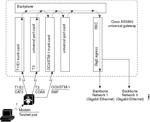
The Cisco AS5850 universal gateway basic interfaces are as follows:
•
•
Figure 1 shows the Cisco AS5850 system architecture.
Figure 1 Cisco AS5850 System Architecture
Route-Switch-Controller Card
The route-switch-controller (RSC) card is the main processor card for the universal gateway. It installs in either slot 6 or slot 7 and plugs directly into the backplane, and performs the following functions:
•
•
•
•
•
•
•
•
Note
The Dial Shelf Interconnect Protocol (DSIP) enables communication between RSC and feature cards:
•
–
–
•
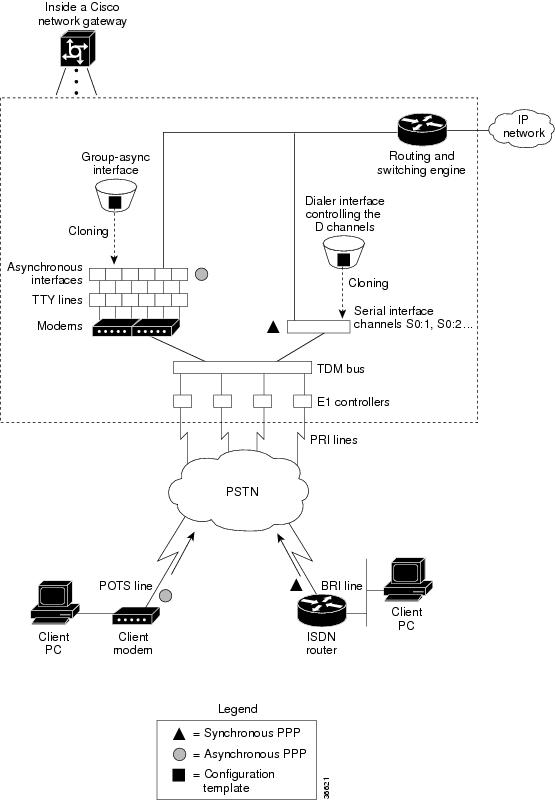
Call-Processing Components
As shown in Figure 2, the following components process a call:
•
•
•
•
•
•
Figure 2 Cisco AS5850 Call-Processing Components
One asynchronous PPP call requires the following:
•
•
•
•
•
One synchronous PPP call requires the following:
•
•
Note
How to Commission the Cisco AS5850 Universal Gateway
This section contains the following information:
•
•
•
•
•
•
•
•
•
•
Task 1. Verifying Basic Setup
To verify that basic system components are functioning, see the following sections:
•
•
•
Analyze the System Boot Dialog
To view the boot sequence through a terminal session, you must have a console connection to the universal gateway before it powers up.
The following boot sequence occurs. Event numbers and comments are inserted in the example to describe the boot sequence.
In this segment, the universal gateway decompresses the system boot image, tests the NVRAM for validity, and decompresses the Cisco OS software image.
System Bootstrap, Version 12.2(2)T, RELEASE SOFTWARE (fc1)Copyright (c) 2000 by cisco Systems, Inc.5850-rsc platform with 524288 Kbytes of main memorySelf decompressing the image : ######################################################################################################################################################################### [OK]Sometimes boot images do not support hardware cards. Error messages look like this sample.
%OIR-3-SEATED: Insert/removal failed
Note
Self decompressing the image :
#######################################################################################
################################################################################## [OK]In this segment the following components are detected:
•
•
•
Restricted Rights LegendUse, duplication, or disclosure by the Government issubject to restrictions as set forth in subparagraph(c) of the Commercial Computer Software - RestrictedRights clause at FAR sec. 52.227-19 and subparagraph(c) (1) (ii) of the Rights in Technical Data and ComputerSoftware clause at DFARS sec. 252.227-7013.cisco Systems, Inc.170 West Tasman DriveSan Jose, California 95134-1706Cisco Internetwork Operating System SoftwareIOS (tm) 5850 Software (C5850-P6-M), Version 12.2(20010828:201655)]Copyright (c) 1986-2001 by cisco Systems, Inc.Compiled Tue 28-Aug-01 16:20 byImage text-base: 0x60008960, data-base: 0x6160E000cisco c5850 (R7K) processor (revision 0.12) with 196608K/65536K bytes of memory.R7000 CPU at 259Mhz, Implementation 39, Rev 2.1, 256KB L2, 2048KB L3 CacheLast reset from Mbus resetChannelized E1, Version 1.0.X.25 software, Version 3.0.0.Bridging software.SuperLAT software (copyright 1990 by Meridian Technology Corp).Primary Rate ISDN software, Version 1.1.1 FastEthernet/IEEE 802.3 interface(s)2 Gigabit Ethernet/IEEE 802.3 interface(s)1404 terminal line(s)24 Channelized T1/PRI port(s)2 Channelized T3 port(s)507K bytes of non-volatile configuration memory.32768K bytes of Compact Flash card at slot 0 (Sector size 128K).16384K bytes of Flash internal SIMM (Sector size 256K).
Note
The following system message and prompt appears.
--- System Configuration Dialog ---Would you like to enter the initial configuration dialog? [yes/no]: noBecause the universal gateway has never been configured, the Cisco IOS software cannot find a startup-config file, so abort the configuration dialog. In this example, the Cisco IOS software is configured manually; the automatic setup script is not used. The RSC card auto-detects the state of each card in the chassis.
00:00:09: %MBUS-3-UNKNOWN_REGISTER: Status change message for register 9 in slot 6,value = 200:00:09: %MBUS-3-UNKNOWN_REGISTER: Status change message for register 0 in slot 6,value = 8800:00:09: %MBUS-3-UNKNOWN_REGISTER: Status change message for register 9 in slot 6,value = 000:00:37: %SYS-7-NV_BLOCK_INIT: Initalized the geometry of nvram00:00:42: %LINK-5-CHANGED: Interface FastEthernet6/0, changed state to initializing00:00:42: %LINK-5-CHANGED: Interface GigabitEthernet6/1, changed state to initializing00:00:42: %DSCREDCLK-5-BSWITCHT: Backup clock matched to the active clock reference,slot 3 line 000:00:43: %DSCREDCLK-5-BNORMAL: Backup clock moving to NORMAL to phase lock to theactive clock00:00:43: %LINEPROTO-5-UPDOWN: Line protocol on Interface FastEthernet6/0, changedstate to down00:00:43: %LINEPROTO-5-UPDOWN: Line protocol on Interface GigabitEthernet6/1, changedstate to down00:00:45: %LINK-5-CHANGED: Interface GigabitEthernet6/1, changed state to administrativelydown00:00:52: %LINK-3-UPDOWN: Interface FastEthernet6/0, changed state to up00:00:53: %LINEPROTO-5-UPDOWN: Line protocol on Interface FastEthernet6/0, changedstate to up00:00:56: %SYS-5-CONFIG_I: Configured from memory by console00:01:15: %LINK-3-UPDOWN: Interface GigabitEthernet6/0, changed state to up00:01:17: %SYS-5-RESTART: System restarted --Cisco Internetwork Operating System SoftwareIOS (tm) 5850 Software (C5850-P6-M), Version 12.1(20001120:130907)[ssangiah-121_5_xv_build 100]Copyright (c) 1986-2000 by cisco Systems, Inc.Compiled Mon 20-Nov-00 05:09 by00:01:17: %LINEPROTO-5-UPDOWN: Line protocol on Interface GigabitEthernet6/0, changedstate to up00:01:17: %SYS-6-BOOTTIME: Time taken to reboot after reload = 209 seconds00:01:17: %OIR-6-REMCARD: Card removed from slot 11, interfaces disabled00:01:17: %OIR-6-REMCARD: Card removed from slot 12, interfaces disabledPress RETURN to get started!Router>Verify the Operating Environment
To verify the operating environment, perform the following steps as appropriate for your system.
Step 1
Step 2
AS5850# show environmentSlot # Exhaust Sensor Inlet Sensor(deg C) (deg C)0 54.5 37.01 50.5 31.52 32.0 32.54 44.5 35.55 44.0 28.56 26.5 24.57 26.5 24.58 41.5 27.59 40.5 29.010 42.0 29.011 33.5 33.013 47.0 32.0Slot # 3.3V 5V MBUS 5V(mv) (mv) (mv)0 3260 4968 50801 3260 4920 50722 3276 4976 50884 3268 4976 50805 3260 4976 51046 3284 5016 51287 3288 4984 51208 3276 4976 50809 3276 4968 508010 3256 4976 508811 3272 4944 507213 3264 4944 5096Slot # 5.15V MBUS 5V 48V AMP_48 1.60V(mv) (mv) (Volt) (Amp) (mv)24 5520 5136 49 13 164024 RAW 690 642 698 209 41025 5536 5136 50 13 180825 RAW 692 642 712 218 452PEMF slot 24: AC Shelf is normalPEMF slot 24: Blower is normal. (MBUS Port2 returns 8E)PEMF slot 25: AC Shelf is normalPEMF slot 25: Blower is normal. (MBUS Port2 returns 8E)Step 3
AS5850# show versionCisco Internetwork Operating System SoftwareIOS (tm) 5850 Software (C5850-P6-M), Version 12.1(20000624:130156)]Copyright (c) 1986-2000 by cisco Systems, Inc.Compiled Thu 20-Jul-00 09:11 byImage text-base: 0x60008908, data-base: 0x612B0000ROM: System Bootstrap, Version 12.0(20000306:065252) [gclendon-rsc-rommon 104],EROM: 5850 Software (C5850-BOOT-M), Version 12.1(20000624:130156) []AS5850 uptime is 18 hours, 30 minutesSystem returned to ROM by reloadSystem image file is "disk0:c5850-p6-mz"cisco c5850 (R7K) processor with 229376K/32768K bytes of memory.R7000 CPU at 262Mhz, Implementation 39, Rev 1.0, 256KB L2, 2048KB L3 CacheLast reset from unexpected valueChannelized E1, Version 1.0.X.25 software, Version 3.0.0.Bridging software.SuperLAT software (copyright 1990 by Meridian Technology Corp).Primary Rate ISDN software, Version 1.1.1 FastEthernet/IEEE 802.3 interface(s)2 Gigabit Ethernet/IEEE 802.3 interface(s)756 terminal line(s)24 Channelized T1/PRI port(s)1 Channelized T3 port(s)507K bytes of non-volatile configuration memory.
Inspect the Feature Cards
To inspect the feature cards, perform the following steps.
Step 1
AS5850# show chassisSystem is in classic-split mode, RSC in slot 6.Slots owned: 0 1 2 3 4 5Slots configured: 0 1 2 3 4 5Slots owned by other: 8 9 10 11 12 13Slot Board CPU DRAM I/O Memory State ElapsedType Util Total (free) Total (free) Time0 24T1 0%/0% 0( 0%) 0( 0%) Booting 00:00:234 CT3_UP216 0%/0% 0( 0%) 0( 0%) Booting 00:00:235 UP324 0%/0% 0( 0%) 0( 0%) Up 00:00:01System set for auto bootPossible feature-card states include unknown, down, resetting, booting, and up. The Up state means that a card can communicate with the RSC card.
Each universal port card contains its own DRAM memory and performs its own call processing. A normal CPU utilization range is 20-40%.
Step 2
a.
Note
b.
AS5850# show dsi6/0 is up, line protocol is upHardware is AmdFE, address is 00b6.eaf4.2b00 (bia 00b6.eaf4.2b00)MTU 1500 bytes, BW 100000 Kbit, DLY 100 usec,reliability 255/255, txload 1/255, rxload 1/255Encapsulation ARPA, loopback not setUnknown duplex, Unknown Speed, 100BaseTX/FXARP type:ARPA, ARP Timeout 04:00:00Last input 00:00:00, output 00:00:00, output hang neverLast clearing of "show interface" counters neverQueueing strategy:fifoOutput queue 0/600, 0 drops; input queue 0/600, 0 drops1 minute input rate 0 bits/sec, 0 packets/sec1 minute output rate 0 bits/sec, 0 packets/sec45114 packets input, 3795862 bytesReceived 0 broadcasts, 0 runts, 0 giants, 0 throttles0 input errors, 0 CRC, 0 frame, 0 overrun, 0 ignored0 watchdog0 input packets with dribble condition detected22342 packets output, 15268108 bytes, 0 underruns(0/0/0)0 output errors, 0 collisions, 1 interface resets0 output errors, 0 collisions, 1 interface resets0 babbles, 0 late collision, 0 deferred0 lost carrier, 0 no carrier0 output buffer failures, 0 output buffers swapped outInterface 6/0Hardware is AMD LagunaADDR:64FD7E24, FASTSEND:6001ED60, MCI_INDEX:0DIST ROUTE ENABLED:0Route Cache Flag:0LADRF=0x0000 0x0000 0x0000 0x0000CSR0 =0x00000072, CSR3 =0x00001044, CSR4 =0x0000491D, CSR15 =0x00008180CSR80 =0x00009900, CSR114=0x00000000, CRDA =0x16462250, CXDA =0x16465230BCR9 =0x00000001 (full-duplex)CSR5 =0x00000001, CSR7 =0x00000A20, CSR100=0x0000F000, CSR125=0x00005C3CBCR2 =0x00001000, BCR9 =0x00000001, BCR18 =0x000019E0, BCR22 =0x0000FF06BCR25 =0x00000017, BCR26 =0x0000000B, BCR27 =0x00000000, BCR32 =0x00004080BCR4 =0x000000C0, BCR7 =0x00000090, BCR20 =0x00000303, BCR39 =0x00000000BCR33 =0x00004800, BCR34 =0x0000FFFFHW filtering information:Promiscuous Mode Enabled, PHY Addr Enabled, Broadcast Addr EnabledPHY Addr=00B6.EAF4.2B00, Multicast Filter=0x0000 0x0000 0x0000 0x0000amdp2_instance=0x64FD9B70, registers=0x48000000, ib=0x6461D20rx ring entries=512, tx ring entries=512rxring=0x6461D80, rxr shadow=0x64FD9D2C, rx_head=77, rx_tail=0txring=0x6463DC0, txr shadow=0x64FDA558, tx_head=327, tx_tail=327, tx_count=0spurious_idon=0, throttled=0, enabled=0, disabled=0rx_framing_err=0, rx_overflow_err=0, rx_buffer_err=0, rx_bpe_err=0rx_soft_overflow_err=0, rx_no_enp=0, rx_discard=0, rx_miss_count=0tx_one_col_err=0, tx_more_col_err=0, tx_no_enp=0, tx_deferred_err=0tx_underrun_err=0, tx_late_collision_err=0, tx_loss_carrier_err=0tx_exc_collision_err=0, tx_buff_err=0, fatal_tx_err=0 tx_limited=0(0)
Note
Caution
Messages appear on the console terminal after the feature card is physically removed from slot 12 and reinserted. Approximately 120 seconds elapse before all these messages appear.
AS5850>04:42:13: %ISDN-6-LAYER2DOWN: Layer 2 for Interface Se1/12/0:0:23, TEI 0 changedto down04:42:46: %DSIPPF-5-DS_KEEPALIVE_LOSS: DSIP Keepalive Loss from slot 1204:42:53: %DSIPPF-5-DS_HELLO: DSIP Hello from slot 12 SucceededAS5850>The following boot sequence occurs in the previous example:
•
•
•
•
c.
AS5850# dsip console slave 12Trying Dial shelf slot 12 ...Entering CONSOLE for slot 12Type "^C^C^C" to end this sessionDA-Slot12>DA-Slot12#DA-Slot12#DA-Slot12#Terminate NIP IO session? [confirm][Connection to Dial shelf slot 12 closed by local host]AS5850#
Note
•
•
•
To learn more about these and other Cisco IOS commands, start at http://www.cisco.com/univercd/cc/td/doc/product/software/ and click on your Cisco IOS release.
Use the DSIP Commands
The RSC card communicates with the feature cards using the following:
•
•
•
Note
To use the DSIP commands, perform the following steps.
Step 1
Note
AS5850# show dsipDSIP transport statistics:IPC : input msgs=595876, bytes=54824426; output msgs=80748, bytes=4884676total consumed ipc msgs=653; total freed ipc msgs = 653transmit contexts in use = 10, free = 246, zombie = 0, invalid = 0ipc getmsg failures = 0, ipc timeouts=0core getbuffer failures=0, api getbuffer failures=0dsip test msgs rcvd = 0, sent = 0CNTL : input msgs=18800, bytes=1282416; output msgs=9585, bytes=5215320getbuffer failures=0DATA : input msgs=540, bytes=19440; output msgs=0, bytes=0DSIP Private Buffer Pool Hits = 0DSIP registered addresses:Shelf0 : Master: 0044.efbe.3d37, Status=localDSIP Clients:-------------ID Name0 Console1 Clock2 Modem3 Logger4 TDM5 Trunk6 Async data7 Unused8 Dial shelf manager9 Unused10 Unused11 RSC Red. UI12 Unused13 NextPort14 Signalling15 Unused16 DSIP MIPC17 Marvel Flow Manager18 gigE19 Unused20 Egress Driver21 DSIP TestDSIP local ports:----------------Client:Portname Portid In-Msgs Bytes Last-i/pConsole:Master 10005 0 0 neverClock:Master 10006 1058 245228 00:00:51Modem:Master 10007 2 28 17:35:41Logger:Master 10008 0 0 neverTDM:Master 10009 2 48 17:35:41Trunk:Master 1000A 51432 4319776 00:00:00Async data:Master 1000B 0 0 neverDial shelf manager:Master 1000D 0 0 neverRSC Red. UI:Master 1000E 0 0 neverNextPort:Master 1000F 737 30736 17:35:15Signalling:Master 10010 0 0 neverDSIP MIPC:Master 10011 0 0 neverMarvel Flow Manager:Master 10012 2 8 17:35:40gigE:Master 10013 2 8 17:35:39Egress Driver:Master 10014 25337 3445832 00:00:00DSIP Test:Master 10015 0 0 neverDSIP remote ports:-----------------Client:Portname Portid Out-Msgs Bytes Last-o/p Last-actModem:Slave1 1080007 326 8008 17:35:57 17:36:34NextPort:Slave1 108000A 56 3904 17:35:58 17:36:33Marvel Flow Manager:Slave1 108000D 2 2700 17:36:31 17:36:31gigE:Slave1 108000E 1 12 17:36:30 17:36:30Clock:Slave13 1140006 1 28 17:35:43 17:35:43Modem:Slave13 1140007 218 6280 17:35:15 17:35:43Trunk:Slave13 1140009 8 4512 17:35:43 17:35:43NextPort:Slave13 114000B 38 2608 17:35:16 17:35:42Marvel Flow Manager:Slave1 114000E 2 2700 17:35:41 17:35:41gigE:Slave13 114000F 1 12 17:35:39 17:35:39DSIP ipc queue:---------------There are 0 IPC messages waiting for acknowledgement in the transmit queue.There are 0 messages currently in use by the system.DSIP ipc nodes:---------------There are 3 nodes in this IPC realm.ID Type Name Last LastSent Heard10000 Local IPC Master 0 01080000 DSIP Dial Shelf:Slave1 33 331140000 DSIP Dial Shelf:Slave13 40 40DSIP version information:------------------------Local DSIP major version = 5, minor version = 2All feature boards are running DSIP versions compatible with router shelfLocal clients registered versions:------------------------------------Client Name Major Version Minor VersionConsole 5 2Clock 2 1Modem 1 0Logger No version No versionTDM No version No versionTrunk No version No versionAsync data No version No versionVOICE 0 0Dial shelf No version No versionRSC Red. UI 0 1NextPort 0 0Signalling 1 5DSIP MIPC No version No versionMarvel Flow No version No versiongigE No version No versionEgress Driv No version No versionDSIP Test No version No versionMismatched remote client versions:Step 2
AS5850# show dsip transportDSIP transport statistics:IPC : input msgs=596027, bytes=54838680; output msgs=80772, bytes=4886020total consumed ipc msgs=653; total freed ipc msgs = 653transmit contexts in use = 10, free = 246, zombie = 0, invalid = 0ipc getmsg failures = 0, ipc timeouts=0core getbuffer failures=0, api getbuffer failures=0dsip test msgs rcvd = 0, sent = 0CNTL : input msgs=18804, bytes=1282744; output msgs=9587, bytes=5215440getbuffer failures=0DATA : input msgs=540, bytes=19440; output msgs=0, bytes=0DSIP Private Buffer Pool Hits = 0DSIP registered addresses:Shelf0 : Master: 0044.efbe.3d37, Status=localAS5850#Step 3
AS5850# show dsip versionDSIP version information:------------------------Local DSIP major version = 5, minor version = 2All feature boards are running DSIP versions compatible with router shelfLocal clients registered versions:------------------------------------Client Name Major Version Minor VersionConsole 5 2Clock 2 1Modem 1 0Logger No version No versionTDM No version No versionTrunk No version No versionAsync data No version No versionVOICE 0 0Dial shelf No version No versionRSC Red. UI 0 1NextPort 0 0Signalling 1 5DSIP MIPC No version No versionMarvel Flow No version No versiongigE No version No versionEgress Driv No version No versionDSIP Test No version No versionMismatched remote client versions:-----------------------------------
Note
Inspect the Initial Running Configuration
The Cisco IOS software creates an initial running configuration. To familiarize yourself with the default settings, inspect the software configuration on the RSC card as follows.
AS5850# show running-configBuilding configuration...Current configuration : 1495 bytes!version 12.2no service single-slot-reload-enableservice timestamps debug uptimeservice timestamps log uptimeno service password-encryption!hostname AS5850!!redundancymode classic-splitno logging bufferedlogging rate-limit console 10 except errors!!resource-pool disablespe link-info poll voice 5!!ip subnet-zeroip cef distributedno ip finger!!controller T3 0/0cablelength 224!controller T3 1/0cablelength 224!!interface FastEthernet6/0no ip addressip route-cache distributedlogging event link-statusshutdown!interface GigabitEthernet6/0no ip addressip route-cache distributedlogging event link-statusshutdownno negotiation auto!interface GigabitEthernet6/1no ip addressip route-cache distributedlogging event link-statusshutdownno negotiation auto!interface Group-Async0no ip addressip route-cache distributedgroup-range 0/00 4/323!ip kerberos source-interface anyip classlessno ip http server!!line con 0logging synchronoustransport input noneline aux 0line vty 0 4line 0/00 1/215activation-character 0disconnect-character 0modem InOutno modem status-pollno modem log rs232escape-character soft 0escape-character 0hold-character 0line 2/00 4/323activation-character 0disconnect-character 0modem InOutno modem status-pollno modem log rs232escape-character soft 0escape-character 0hold-character 0!endExplore the Cisco IOS File System
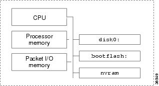
Familiarize yourself with the file system and memory storage areas. The Cisco IOS file system provides a consolidated interface to the following:
•
•
•
Figure 3 shows the memory locations inside the Cisco AS5850.
Figure 3 Cisco AS5850 Memory Locations
Table 1 describes the memory types on the Cisco AS5850.
To inspect the file system, perform the following steps as appropriate for your system.
Step 1
AS5850# show file systemsFile Systems:Size(b) Free(b) Type Flags Prefixes31916032 14307328 flash rw disk0:- - network rw rcp:- - opaque rw null:- - opaque rw system:- - network rw tftp:520184 481796 nvram rw nvram:* 15990784 11484640 flash rw bootflash: flash:- - network rw ftp:AS5850#Step 2
AS5850# dir system:Directory of system:/1 -rw- 51613 <no date> running-config2 dr-x 0 <no date> memory12 dr-x 0 <no date> vfilesNo space information availableAS5850#
Note
Step 3
AS5850# pwddisk0:AS5850# dirDirectory of disk0:/3 -rw- 325539 Jan 01 2000 04:33:44 np_6_83_2.spe83 -rw- 8987568 Jan 02 2000 02:45:30 c5850-p6-mz.Aug232278 -rw- 8617256 Jan 01 2000 00:17:16 c5850-p6-mz.Sep531916032 bytes total (13299712 bytes free)Step 4
AS5850# dir bootflash:Directory of bootflash:/1 -rw- 1863976 Mar 01 1993 00:05:28 c5850-boot-mz.May2615990784 bytes total (14100676 bytes free)
Note
Step 5
•
•
•
AS5850# dir nvram:Directory of nvram:/1 -rw- 739 <no date> startup-config2 ---- 24 <no date> private-config3 -rw- 739 <no date> underlying-config129016 bytes total (128277 bytes free)AS5850#
Verify Memory Usage
Use the show memory summary command to do the following:
•
•
–
–
To determine and calculate memory usage, perform the following steps.
Step 1
AS5850# show memory summaryHead Total(b) Used(b) Free(b) Lowest(b) Largest(b)Processor 616CCD20 479408864 44937912 434470952 431866220 431896392I/O E000000 33554432 2633464 30920968 30066928 30132444Processor memoryAlloc PC Size Blocks Bytes What0x60009E3C 172 4 688 Init0x6000F748 432 1080 466560 IDB: Serial Info0x6000F748 436 1 436 IDB: Serial Info0x6000F748 444 1 444 IDB: Serial Info0x60017BE4 2048 1 2048 Init0x60017C10 4096 1 4096 Init0x6001B09C 184 1 184 Init0x600265F0 128 25 3200 RIF Cache0x6006CDFC 176 1086 191136 FIB: FIBIDB0x6006D514 30000 1 30000 FIB: HWIDB MAP TABLE0x6006D6A8 560 1086 608160 FIB: FIBHWIDB0x6006D8CC 30000 1 30000 Init0x6006EF08 1460 1 1460 RemoveReceiveHash Entries0x60071274 1900 1 1900 FIB one path chunk0x60071274 65496 1 65496 FIB one path chunk0x6007CB74 1072 1 1072 FIB: Control Block0x6007CBA0 32 1 32 Init0x6007CE4C 30000 1 30000 FIB: Root-table0x6007CE68 30000 1 30000 FIB: Cblk-table0x6007CED8 144 1 144 FIB ndb0x6007CEF4 384 1 384 FIB rdb0x6007CF30 92 1 92 Init
Caution
Table 2 describes the significant fields in the previous display.
Step 2
•
•
•
Total memory (457.2 MB) = Used memory (42.9 MB) + free memory (414.3 MB)
Step 3
Total Processor = Total RAM - Cisco IOS software (use the show version command to get the MB assigned for all of Cisco IOS software + processor)
cisco c5850 (R7K) processor (revision 0.12) with 491520K/32768K bytes of memory.491520K = 480 MB
+ 32768K = 32 MB
Total = 512 MB (what you purchased)
Verify CPU Utilization
High utilization causes network performance problems. Knowing when the gateway is running at over 50% utilization is critical because the gateway might start dropping packets if an unexpected traffic burst comes through, or if OSPF gets recalculated. Fast switching reduces CPU utilization.
To verify CPU utilization, perform the following steps.
Step 1
AS5850# show processes cpuCPU utilization for five seconds: 0%/0%; one minute: 0%; five minutes: 0%PID Runtime(ms) Invoked uSecs 5Sec 1Min 5Min TTY Process1 0 88 0 0.00% 0.00% 0.00% 0 Load Meter2 1856 14859 124 0.00% 0.44% 0.28% 0 Exec3 384 63 6095 0.00% 0.09% 0.04% 0 Check heaps4 0 1 0 0.00% 0.00% 0.00% 0 Chunk Manager5 0 1 0 0.00% 0.00% 0.00% 0 Pool Manager6 0 2 0 0.00% 0.00% 0.00% 0 Timers7 0 2 0 0.00% 0.00% 0.00% 0 Serial Backgroun8 52 6 8666 0.00% 0.00% 0.00% 0 RSC Ucode Downlo9 0 2 0 0.00% 0.00% 0.00% 0 DS OIR Handler o10 0 469 0 0.00% 0.00% 0.00% 0 FB manager11 12 1873 6 0.00% 0.00% 0.00% 0 MBUS System12 64 31 2064 0.00% 0.00% 0.00% 0 ARP Input13 0 117 0 0.00% 0.00% 0.00% 0 HC Counter Timer14 0 2 0 0.00% 0.00% 0.00% 0 DDR Timers15 0 2 0 0.00% 0.00% 0.00% 0 Dialer event16 4 2 2000 0.00% 0.00% 0.00% 0 Entity MIB API17 0 1 0 0.00% 0.00% 0.00% 0 RM PROCESS18 0 1 0 0.00% 0.00% 0.00% 0 RM PROCESS19 0 1 0 0.00% 0.00% 0.00% 0 RM PROCESS20 0 1 0 0.00% 0.00% 0.00% 0 RM PROCESS21 0 2 0 0.00% 0.00% 0.00% 0 CAS ProcessPID Runtime(ms) Invoked uSecs 5Sec 1Min 5Min TTY Process22 0 2 0 0.00% 0.00% 0.00% 0 IPC Zone Manager23 0 471 0 0.00% 0.00% 0.00% 0 IPC Periodic Tim24 28 275 101 0.00% 0.00% 0.00% 0 IPC Seat Manager25 0 1 0 0.00% 0.00% 0.00% 0 SERIAL A'detect26 0 1 0 0.00% 0.00% 0.00% 0 Critical Bkgnd27 8 496 16 0.00% 0.00% 0.00% 0 Net Background28 0 28 0 0.00% 0.00% 0.00% 0 Logger29 0 435 0 0.00% 0.00% 0.00% 0 TTY Background30 4 471 8 0.00% 0.00% 0.00% 0 Per-Second Jobs31 0 3 0 0.00% 0.00% 0.00% 0 rsc_sync_process32 0 59 0 0.00% 0.00% 0.00% 0 Net Input33 476 89 5348 0.08% 0.10% 0.08% 0 Compute load avg34 48 8 6000 0.00% 0.00% 0.00% 0 Per-minute Jobs35 0 7554 0 0.00% 0.00% 0.00% 0 RSC Redundancy36 4 16258 0 0.00% 0.00% 0.00% 0 MBUS monitoring37 0 2 0 0.00% 0.00% 0.00% 0 marker38 0 469 0 0.00% 0.00% 0.00% 0 MIPC Periodic Ti39 0 331 0 0.00% 0.00% 0.00% 0 MIPC Server Proc40 0 1 0 0.00% 0.00% 0.00% 0 FDM TCAM Daemon41 428 3457 123 0.00% 0.00% 0.00% 0 NIP Boot Daemon42 72 3548 20 0.00% 0.00% 0.00% 0 DSIP Daemon43 0 1 0 0.00% 0.00% 0.00% 0 DSIP INTRAPI DaePID Runtime(ms) Invoked uSecs 5Sec 1Min 5Min TTY Process44 0 571 0 0.00% 0.00% 0.00% 0 DS RSC Clock Dae45 0 107 0 0.00% 0.00% 0.00% 0 Env Mon46 0 2 0 0.00% 0.00% 0.00% 0 CSM Periodic47 0 1 0 0.00% 0.00% 0.00% 0 Portware Downloa48 0 1 0 0.00% 0.00% 0.00% 0 COT Timer proces49 0 1 0 0.00% 0.00% 0.00% 0 COT Queue proces50 4 13 307 0.00% 0.00% 0.00% 0 PM SPE SM Proces52 0 2 0 0.00% 0.00% 0.00% 0 PM FW Process53 0 2 0 0.00% 0.00% 0.00% 0 PM DOWNLOAD MAIN54 12 70 171 0.00% 0.00% 0.00% 0 EST msg processi55 0 8 0 0.00% 0.00% 0.00% 0 VRM reset proces56 0 1 0 0.00% 0.00% 0.00% 0 VRM57 0 1 0 0.00% 0.00% 0.00% 0 PM CSM Event Bac58 4 36 111 0.00% 0.00% 0.00% 0 RSC PIF Interfac59 0 471 0 0.00% 0.00% 0.00% 0 DSBIC Periodic60 24 314 76 0.00% 0.00% 0.00% 0 IP Input61 48 122 393 0.00% 0.00% 0.00% 0 CDP Protocol62 0 74 0 0.00% 0.00% 0.00% 0 IP Background63 0 1 0 0.00% 0.00% 0.00% 0 PPP IP Add Route64 0 9 0 0.00% 0.00% 0.00% 0 Adj Manager65 0 1 0 0.00% 0.00% 0.00% 0 TCP Timer66 0 1 0 0.00% 0.00% 0.00% 0 TCP Protocols67 0 1 0 0.00% 0.00% 0.00% 0 Probe Input68 0 1 0 0.00% 0.00% 0.00% 0 RARP Input69 0 1 0 0.00% 0.00% 0.00% 0 HTTP Timer70 0 1 0 0.00% 0.00% 0.00% 0 Socket Timers71 0 2 0 0.00% 0.00% 0.00% 0 DHCPD Receive72 0 8 0 0.00% 0.00% 0.00% 0 IP Cache Ager73 0 1 0 0.00% 0.00% 0.00% 0 COPS74 0 1 0 0.00% 0.00% 0.00% 0 PAD InCall75 0 2 0 0.00% 0.00% 0.00% 0 X.25 Background76 0 2 0 0.00% 0.00% 0.00% 0 Emulator77 0 8 0 0.00% 0.00% 0.00% 0 TCP Intercept Ti78 0 1 0 0.00% 0.00% 0.00% 0 Time Range Proce80 0 1 0 0.00% 0.00% 0.00% 0 ISDN Timer81 0 1 0 0.00% 0.00% 0.00% 0 sssapp82 0 2 0 0.00% 0.00% 0.00% 0 tcl ivr app83 0 2 0 0.00% 0.00% 0.00% 0 tcl ivr app84 0 2 0 0.00% 0.00% 0.00% 0 tcl ivr app85 0 2 0 0.00% 0.00% 0.00% 0 tcl ivr app86 0 2 0 0.00% 0.00% 0.00% 0 tcl ivr app87 0 2 0 0.00% 0.00% 0.00% 0 tcl ivr app88 0 2 0 0.00% 0.00% 0.00% 0 tcl ivr app89 4 2 2000 0.00% 0.00% 0.00% 0 tcl ivr appPID Runtime(ms) Invoked uSecs 5Sec 1Min 5Min TTY Process90 0 1 0 0.00% 0.00% 0.00% 0 CallMIB Backgrou91 0 1 0 0.00% 0.00% 0.00% 0 ISDNMIB Backgrou92 0 1 0 0.00% 0.00% 0.00% 0 SNMP ConfCopyPro93 0 1 0 0.00% 0.00% 0.00% 0 Syslog Traps94 0 3 0 0.00% 0.00% 0.00% 0 AAA Accounting96 0 4 0 0.00% 0.00% 0.00% 0 DHCPD Timer97 0 121 0 0.00% 0.00% 0.00% 0 DHCPD DatabaseStep 2
Table 3 describes the significant output fields in the previous example.
Whenever memory cannot be allocated to a process request (a memory leak), a console error message appears. To identify the problem, inspect the first few output lines of the show memory summary command and show processor memory command.
Task 2. Configuring Basic Cisco IOS Software
To apply a basic running configuration to the universal gateway, see the following sections:
•
Tip
Configure Host Name, Enable-Secret Password, and Time Stamps
You assign a host name to the universal gateway, specify an enable-secret password, and turn on time stamps.
•
•
•
•
To configure a hostname, enable-secret passwords, and time stamps, perform the following steps.
Step 1
ip hostname Gatewayenable secret yourpasswordhereservice password-encryptionservice timestamps debug datetime msecservice timestamps log datetime msec
Note
Step 2
Gateway# disableGateway> enablePassword:Gateway# show privilegeCurrent privilege level is 15Gateway#
Configure Local AAA Security
Configure AAA to perform login authentication by using the local username database. The login keyword authenticates EXEC-shell users. Additionally, configure PPP authentication to use the local database if the session was not already authenticated by login.
AAA is the Cisco IOS software security model used on all Cisco devices. AAA provides the primary framework through which you set up access control on the universal gateway.
In this basic discussion, the same authentication method is used on all interfaces. AAA is set up to use the local database configured on the universal gateway. This local database is created with the username configuration commands.
Note
To configure local security, perform the following steps.
Step 1
Gateway# configure terminalEnter configuration commands, one per line. End with CNTL/Z.Gateway(config)#Step 2
Gateway(config)# username admin password adminpasshereGateway(config)# username Harry password HarrypasshereStep 3
Gateway(config)# aaa new-modelGateway(config)# aaa authentication login default localGateway(config)# aaa authentication ppp default if-needed localStep 4
Gateway(config)# Ctrl-ZGateway#Step 5
Caution
Gateway# loginUser Access VerificationUsername: adminPassword:Gateway#A successful login means your local username works on any TTY or VTY line. Do not disconnect your session until you can log in.
Tip
Note
Table 4 describes the configuration line-item commands.
Set Up a Login Banner
Create a login banner. However, do not tell users what device they are connecting to until after they log on. Providing device-sensitive information can tempt unauthorized users to hack into the system.
To set up a login banner, perform the following steps.
Step 1
Gateway(config)# banner login |Enter TEXT message. End with the character '|'.This is a secured device.Unauthorized use is prohibited by law.|Gateway(config)#^ZGateway#Step 2
Gateway#Gateway# loginThis is a secured device.Unauthorized use is prohibited by law.User Access VerificationUsername: adminPassword:Gateway#
Configure Basic IP
To configure a basic dial-access service of two loopback interfaces, bring up one Fast Ethernet interface, and add an IP route to the default gateway, perform the following steps.
Step 1
!interface Loopback0ip address 172.22.99.1 255.255.255.0!interface Loopback1ip address 172.22.90.1 255.255.255.0!interface FastEthernet0/1/0ip address 172.22.66.23 255.255.255.0!ip route 0.0.0.0 0.0.0.0 172.22.66.1!The advantage of assigning a gateway's IP address to a loopback rather than a physical interface is that a loopback interface never goes down. The roles of the two loopback interfaces is as follows:
•
•
Step 2
Gateway# ping 172.22.66.1Type escape sequence to abort.Sending 5, 100-byte ICMP Echos to 172.22.66.1, timeout is 2 seconds:.!!!!Success rate is 80 percent (4/5), round-trip min/avg/max = 1/1/1 msGateway#This step verifies that you have IP connectivity with another device on the subnet. If the ping succeeds to the default gateway, try pinging the DNS server in your backbone. Make sure the backbone is configured to get to the universal gateway; otherwise, the ping does not work. Configure the backbone gateways to support the routes to the networks that you are using.
Note
Task 3. Configuring Channelized T1 or E1
This section shows how to configure channelized T1 or E1. You can allocate the available channels for channelized E1 and T1 in the following ways:
•
•
•
•
•
To configure a basic T1 or E1 controller, perform the following steps.
Step 1
Gateway> enablePassword: passwordGateway#Step 2
Gateway# configure terminalEnter configuration commands, one per line. End with CNTL/Z.Gateway(config)#Step 3
Gateway(config)# controller [t1 | e1] slot/portGateway(config-controller)#for the Sonet controller:
Router(config)# controller E1 slot/port.path:E1 contollerRouter(config-controller)#Step 4
Gateway(config-controller)# framing esfor enter the framing type for the CE1 controller.
Gateway(config-controller)# framing crc4Step 5
Gateway(config-controller)# linecode b8zsor define the line code as high-density bipolar 3 (HDB3) for the CE1 controller.
Gateway(config-controller)# linecode hdb3Step 6
Gateway(config-controller)# Ctrl-ZGateway#
Tip
Verify
To verify that your controller is up and running and no alarms have been reported:
•
Gateway# show controller t1 1/7T1 1/7 is up.No alarms detected.Framing is ESF, Line Code is B8ZS, Clock Source is Line Primary.Version info of slot 2: HW: 2, Firmware: 14, NEAT PLD: 13, NR Bus PLD: 19Data in current interval (476 seconds elapsed):0 Line Code Violations, 0 Path Code Violations0 Slip Secs, 0 Fr Loss Secs, 0 Line Err Secs, 0 Degraded Mins0 Errored Secs, 0 Bursty Err Secs, 0 Severely Err Secs, 0 Unavail SecsTotal Data (last 24 hours)0 Line Code Violations, 0 Path Code Violations,0 Slip Secs, 0 Fr Loss Secs, 0 Line Err Secs, 0 Degraded Mins,0 Errored Secs, 0 Bursty Err Secs, 0 Severely Err Secs, 0 Unavail Secs•
–
–
Tip
•
•
•
Task 4. Configuring Channelized T3
Your CT3 card offers 28 individual T1 channels (bundled in the T3) for serial transmission of voice and data. The CT3 link supports the maintenance data link channel in C-bit parity mode and also payload and network loopbacks. The T1s multiplexed in the CT3 link support facilities data link (FDL) in extended super frame (ESF) framing.
To configure channelized T3, perform the following steps.
Step 1
Gateway> enablePassword: passwordGateway#Step 2
Gateway# configure terminalEnter configuration commands, one per line. End with CNTL/Z.Gateway(config)#Step 3
Gateway(config)# controller t3 slot/portGateway(config-controller)#Step 4
Gateway(config-controller)# framing c-bitStep 5
Gateway(config-controller)# clock source lineStep 6
Gateway(config-controller)# cablelength 450Step 7
Gateway(config-controller)# t1 1-28 controlleror omit specified T1 controllers while configuring others. In this instance, T1 controllers 11-14, 21, 22, and 24-28 are not configured.
Gateway(config-controller)# t1 1-10,15-20,23 controllerStep 8
Gateway(config-controller)# Ctrl-ZGateway#
Tip
Verify
To verify that your controller is up and running and no alarms have been reported:
•
Gateway# show controller t3 1/0T3 1/0 is up.Applique type is Channelized T3No alarms detected.MDL transmission is disabledFEAC code received:No code is being receivedFraming is C-BIT Parity, Line Code is B3ZS, Clock Source is InternalData in current interval (270 seconds elapsed):0 Line Code Violations, 0 P-bit Coding Violation0 C-bit Coding Violation, 0 P-bit Err Secs0 P-bit Severely Err Secs, 0 Severely Err Framing Secs0 Unavailable Secs, 0 Line Errored Secs0 C-bit Errored Secs, 0 C-bit Severely Errored SecsTotal Data (last 32 15 minute intervals):0 Line Code Violations, 0 P-bit Coding Violation,0 C-bit Coding Violation, 0 P-bit Err Secs,0 P-bit Severely Err Secs, 0 Severely Err Framing Secs,0 Unavailable Secs, 0 Line Errored Secs,0 C-bit Errored Secs, 0 C-bit Severely Errored SecsTask 5. Configuring ISDN PRI
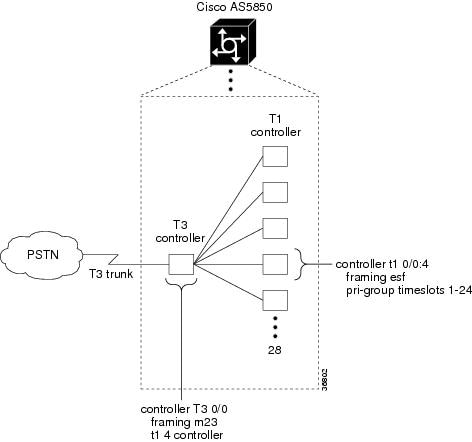
Figure 4 displays the logical controller components inside a Cisco AS5850. The figure demonstrates that a T3 trunk card requires T1 and T3 controller configuration settings. In the figure, only the fourth controller is configured. There are a total of 28 T1 controllers to configure.
Figure 4 Matching Controller Settings
Channelized T1 ISDN PRI offers 23 B channels and 1 D channel. Channelized E1 ISDN PRI offers 30 B channels and 1 D channel. Channel 24 is the D channel for T1, and channel 16 is the D channel for E1. ISDN provides out-of-band signaling using the D channel for signaling and the B channels for user data.
Note
•
To configure ISDN PRI, perform the following steps.
Step 1
Gateway> enablePassword: passwordGateway#Step 2
Gateway# configure terminalEnter configuration commands, one per line. End with CNTL/Z.Gateway(config)#Step 3
Gateway(config)# isdn switch-type switch-type
Note
Note
Step 4
Gateway(config)# controller t1 1/0or
Gateway(config)# controller t3 7/0:16or
Specify the E1 controller you want to configure.
Gateway(config)# controller e1 1/0or, for Sonet controller
Router(config)# controller E1 slot/port.path:E1 contoller
Note
Step 5
Gateway(config-controller)# pri-group [timeslots range]
Note
For CE1 ISDN PRI—If you do not specify the time slots, the specified controller is configured for 30 B channels and 1 D channel. B channel numbers range from 1 to 31; channel 16 is the D channel for E1. Corresponding serial interface numbers range from 0 to 30. In commands, the D channel is interface serial slot/port:15—for example, interface serial 1/0:15.Step 6
Gateway(config-controller)# Ctrl-ZGateway#Step 7
Gateway# show controller t3T3 0/0 is up.Applique type is Channelized T3No alarms detected.FEAC code received: No code is being receivedFraming is M23, Line Code is B3ZS, Clock Source is InternalData in current interval (201 seconds elapsed):0 Line Code Violations, 0 P-bit Coding Violation0 C-bit Coding Violation, 0 P-bit Err Secs0 P-bit Severely Err Secs, 0 Severely Err Framing Secs0 Unavailable Secs, 0 Line Errored Secs0 C-bit Errored Secs, 0 C-bit Severely Errored SecsTotal Data (last 1 15 minute intervals):30664 Line Code Violations, 49191 P-bit Coding Violation,47967 C-bit Coding Violation, 0 P-bit Err Secs,0 P-bit Severely Err Secs, 0 Severely Err Framing Secs,2 Unavailable Secs, 0 Line Errored Secs,10 C-bit Errored Secs, 10 C-bit Severely Errored SecsGateway#Gateway# show controller T1 0/0:4T1 0/0:4 is up.Applique type is Channelized T1Cablelength is shortNo alarms detected.Framing is ESF, Line Code is AMI, Clock Source is Line.Data in current interval (240 seconds elapsed):0 Line Code Violations, 0 Path Code Violations0 Slip Secs, 0 Fr Loss Secs, 0 Line Err Secs, 0 Degraded Mins0 Errored Secs, 0 Bursty Err Secs, 0 Severely Err Secs, 0 Unavail SecsData in Interval 1:0 Line Code Violations, 8 Path Code Violations11 Slip Secs, 26 Fr Loss Secs, 0 Line Err Secs, 0 Degraded Mins0 Errored Secs, 0 Bursty Err Secs, 0 Severely Err Secs, 26 Unavail SecsTotal Data (last 1 15 minute intervals):0 Line Code Violations, 8 Path Code Violations,11 Slip Secs, 26 Fr Loss Secs, 0 Line Err Secs, 0 Degraded Mins,0 Errored Secs, 0 Bursty Err Secs, 0 Severely Err Secs, 26 Unavail Secs#Step 8
Gateway# clear counter t3Gateway# show controller t3In the display output, focus on the data in the current interval. Error counters stop increasing when the controller is configured correctly.
From the reference point of the universal gateway, Table 6 provides a list of E1 alarm conditions and descriptions.
Note
Step 9
Gateway# show ip interface brief | inc :23Serial0/0:4:23 unassigned YES NVRAM up upGateway#Step 10
Gateway# show interface s0/0:4:23
Tip
Task 6. Configuring the Serial Interfaces
Configure the serial D channels to route incoming voice calls from the PSTN to the integrated modems. The behavior of the B channels is controlled by the D-channel configuration instructions. The D channel is the signaling channel.
Table 7 describes the relationship between T1 controllers and serial interfaces.
•
•
•
To configure the serial interfaces, perform the following steps.
Step 1
Gateway(config)# interface serial 1/0/0:4:23Gateway(config-if)# isdn incoming-voice modemStep 2
a.
Gateway# show isdn statusGlobal ISDN Switchtype = primary-niISDN Serial0/0:4:23 interfacedsl 0, interface ISDN Switchtype = primary-5essLayer 1 Status:ACTIVELayer 2 Status:TEI = 0, Ces = 1, SAPI = 0, State = MULTIPLE_FRAME_ESTABLISHEDLayer 3 Status:0 Active Layer 3 Call(s)Activated dsl 0 CCBs = 0The Free Channel Mask: 0x807FFFFFTotal Allocated ISDN CCBs = 0b.
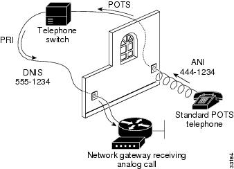
Gateway# show isdn servicePRI Channel Statistics:ISDN Se0/0:4:23, Channel [1-24]Configured Isdn Interface (dsl) 0Channel State (0=Idle 1=Propose 2=Busy 3=Reserved 4=Restart 5=Maint_Pend)0 0 0 0 0 0 0 0 0 0 0 0 0 0 0 0 0 0 0 0 0 0 0 3Service State (0=Inservice 1=Maint 2=Outofservice)0 0 0 0 0 0 0 0 0 0 0 0 0 0 0 0 0 0 0 0 0 0 0 0Step 3
Figure 5 Sending a POTS Telephone Call to a Network Gateway
Note
•
•
Task 7. Configuring Ports and Lines
Ports and lines are configured after the following occur:
•
•
Each modem is mapped to a dedicated asynchronous line inside the universal gateway. After the modem inout command is applied to the lines, the gateway is ready to accept modem calls.
AAA security is applied to the lines by the aaa new-model command and aaa authentication login default local command. AAA performs logon authentication by using the local username database. The login keyword authenticates EXEC-shell users.
Note
To configure ports and lines, perform the following steps.
Step 1
Gateway(config)# line 2/00 10/323Gateway(config-line)# modem InOut
Note
Step 2
Gateway# show speStep 3
TTY line numbers map to specific slots. Each slot is hard-coded with 324 TTY lines. In the example, the first modem card is in slot 1.
Gateway# show SPE modem 1/00
Task 8. Enabling IP Basic Setup
To tune IP routing behavior and domain-name services for EXEC-shell users, perform the following steps.
Step 1
Gateway(config)# ip subnet-zeroGateway(config)# no ip source-routeGateway(config)# ip classlessTable 8 describes the previous commands.
Step 2
ip domain-lookupip host aurora 172.22.100.9ip domain-name the.docip name-server 172.22.11.10ip name-server 172.22.12.10Table 9 describes the previous commands.
Task 9. Testing Asynchronous EXEC-Shell Connections
This task verifies that the following components are working:
•
•
•
The Cisco IOS software provides a command-line interface (CLI) called the EXEC. The EXEC has the following properties:
•
•
–
–
–
–
While performing this task, some administrators try to make complex services function, such as PPP-based web browsing. However, many other elements still need to be configured (for example, PPP and IPCP) before these services may be configured.
The asynchronous-shell test ensures that the EXEC log-in prompt can be accessed by a client modem. Taking a layered approach to building a network isolates problems and saves time.
Note
•
To test asynchronous EXEC-shell connections, perform the following steps.
Step 1
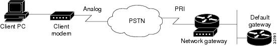
Figure 6 Network Test Environment
Step 2
atOKStep 3
atdt5551234CONNECT 28800 V42bisStep 4
This is a secured device.Unauthorized use is prohibited by law.User Access VerificationUsername: theuserPassword:Gateway>Step 5
Gateway# show callerActive IdleLine User Service Time Timecon 0 admin TTY 00:13:43 00:00:00tty 648 theuser TTY 00:00:20 00:00:08Gateway# show caller user theuserUser: theuser, line tty 436, service TTYActive time 00:00:34, Idle time 00:00:09Timeouts: Absolute Idle IdleSession ExecLimits: - - 00:10:00Disconnect in: - - 00:09:50TTY: Line 1/00DS0: (slot/unit/channel)=0/4/2Status: Ready, Active, No Exit BannerCapabilities: Hardware Flowcontrol In, Hardware Flowcontrol OutModem Callout, Modem RI is CDModem State: ReadyGateway#Step 6
Gateway# telnet 172.22.66.26Trying 172.22.66.26 ... OpenUser Access VerificationUsername: adminPassword:Gateway#
Task 10. Configuring GigE Egress
To commission Gigabit Ethernet service, perform the following steps.
Note
Step 1
Gateway# config tGateway(config)# interface GigabitEthernet6/1Gateway(config-if)# ip address 172.21.101.50 255.255.255.0Configure additional IP addresses as required.
Step 2
Gateway(config-if)# no shutdownStep 3
Gateway# show interface gigabitethernet6/1GigabitEthernet6/1 is up, line protocol is upStep 4
Gateway# ping 172.22.66.1Sending 5, 100-byte ICMP Echos to 172.22.66.1, timeout is 2 seconds:.!!!!Success rate is 80 percent (4/5), round-trip min/avg/max = 1/1/1 msGateway#
Task 11. Confirming the Final Running Configuration
After you complete the tasks in this section, your final running configuration looks like this.
Gateway# show running-configBuilding configuration...Current configuration:!version 12.2service timestamps debug uptimeservice timestamps log uptimeno service password-encryption!hostname Gateway!resource-pool disable!modem-pool Defaultpool-range 0/0-0/215,1/0-1/323,13/0-13/215!ip subnet-zeroip host aurora 172.21.100.100ip domain-name the.docip name-server 172.22.11.10ip name-server 172.22.12.11!redundancymode classic-splitisdn switch-type primary-5ess!controller T3 0/0framing m23cablelength 0t1 1-2 controller!controller T1 0/0:1framing esfpri-group timeslots 1-24!controller T1 0/0:2framing esfpri-group timeslots 1-24!interface Serial0/0:1:23no ip addressip mroute-cacheisdn switch-type primary-5essisdn incoming-voice modem!interface Serial0/0:2:23no ip addressip mroute-cacheisdn switch-type primary-5essisdn incoming-voice modem!interface FastEthernet6/0no ip addressip route-cache distributedlogging event link-statusshutdown!interface GigabitEthernet6/0no ip addressip route-cache distributedlogging event link-statusshutdownno negotiation auto!interface GigabitEthernet6/1no ip addressip route-cache distributedlogging event link-statusshutdownno negotiation auto!interface Async0/00no ip addressip route-cache distributed!interface Async0/01no ip addressip route-cache distributed!interface Async0/02no ip addressip route-cache distributed!interface Async0/03no ip addressip route-cache distributed!interface Group-Async0no ip addressip route-cache distributedno group-range!ip classlessno ip http serverip pim ssm!line con 0transport input noneline aux 0line vty 0 4line 0/00 0/215modem InOutno modem ibcno modem status-pollno modem log rs232line 1/00 1/323modem InOutno modem ibcno modem status-pollno modem log rs232line 13/00 13/215modem InOutno modem ibcno modem status-pollno modem log rs232endIf your configuration is close to the above, your Cisco AS5850 is now configured for basic dial-up services. If your configuration differs significantly, retrace your steps to make sure no sections were skipped.
Note
Additional References
This section contains the following information:
•
•
•
Obtaining Documentation
Cisco documentation and additional literature are available on Cisco.com. Cisco also provides several ways to obtain technical assistance and other technical resources. These sections explain how to obtain technical information from Cisco Systems.
Cisco.com
You can access the most current Cisco documentation at this URL:
http://www.cisco.com/web/learning/le3/ccie/index.html
You can access the Cisco website at this URL:
You can access international Cisco websites at this URL:
http://www.cisco.com/public/countries_languages.shtml
Documentation DVD
Cisco documentation and additional literature are available in a Documentation DVD package, which may have shipped with your product. The Documentation DVD is updated regularly and may be more current than printed documentation. The Documentation DVD package is available as a single unit.
Registered Cisco.com users (Cisco direct customers) can order a Cisco Documentation DVD (product number DOC-DOCDVD=) from the Ordering tool or Cisco Marketplace.
Cisco Ordering tool:
http://www.cisco.com/en/US/partner/ordering/
Cisco Marketplace:
http://www.cisco.com/go/marketplace/
Ordering Documentation
You can find instructions for ordering documentation at this URL:
http://www.cisco.com/univercd/cc/td/doc/es_inpck/pdi.htm
You can order Cisco documentation in these ways:
•
http://www.cisco.com/en/US/partner/ordering/
•
Documentation Feedback
You can send comments about technical documentation to bug-doc@cisco.com.
You can submit comments by using the response card (if present) behind the front cover of your document or by writing to the following address:
Cisco Systems
Attn: Customer Document Ordering
170 West Tasman Drive
San Jose, CA 95134-9883We appreciate your comments.
Cisco Product Security Overview
Cisco provides a free online Security Vulnerability Policy portal at this URL:
http://www.cisco.com/en/US/products/products_security_vulnerability_policy.html
From this site, you can perform these tasks:
•
•
•
A current list of security advisories and notices for Cisco products is available at this URL:
If you prefer to see advisories and notices as they are updated in real time, you can access a Product Security Incident Response Team Really Simple Syndication (PSIRT RSS) feed from this URL:
http://www.cisco.com/en/US/products/products_psirt_rss_feed.html
Reporting Security Problems in Cisco Products
Cisco is committed to delivering secure products. We test our products internally before we release them, and we strive to correct all vulnerabilities quickly. If you think that you might have identified a vulnerability in a Cisco product, contact PSIRT:
•
•
Tip
Never use a revoked or an expired encryption key. The correct public key to use in your correspondence with PSIRT is the one that has the most recent creation date in this public key server list:
http://pgp.mit.edu:11371/pks/lookup?search=psirt%40cisco.com&op=index&exact=on
In an emergency, you can also reach PSIRT by telephone:
•
•
Obtaining Technical Assistance
For all customers, partners, resellers, and distributors who hold valid Cisco service contracts, Cisco Technical Support provides 24-hour-a-day, award-winning technical assistance. The Cisco Technical Support Website on Cisco.com features extensive online support resources. In addition, Cisco Technical Assistance Center (TAC) engineers provide telephone support. If you do not hold a valid Cisco service contract, contact your reseller.
Cisco Technical Support Website
The Cisco Technical Support Website provides online documents and tools for troubleshooting and resolving technical issues with Cisco products and technologies. The website is available 24 hours a day, 365 days a year, at this URL:
http://www.cisco.com/techsupport
Access to all tools on the Cisco Technical Support Website requires a Cisco.com user ID and password. If you have a valid service contract but do not have a user ID or password, you can register at this URL:
http://tools.cisco.com/RPF/register/register.do
Note
Submitting a Service Request
Using the online TAC Service Request Tool is the fastest way to open S3 and S4 service requests. (S3 and S4 service requests are those in which your network is minimally impaired or for which you require product information.) After you describe your situation, the TAC Service Request Tool provides recommended solutions. If your issue is not resolved using the recommended resources, your service request is assigned to a Cisco TAC engineer. The TAC Service Request Tool is located at this URL:
http://www.cisco.com/techsupport/servicerequest
For S1 or S2 service requests or if you do not have Internet access, contact the Cisco TAC by telephone. (S1 or S2 service requests are those in which your production network is down or severely degraded.) Cisco TAC engineers are assigned immediately to S1 and S2 service requests to help keep your business operations running smoothly.
To open a service request by telephone, use one of the following numbers:
Asia-Pacific: +61 2 8446 7411 (Australia: 1 800 805 227)
EMEA: +32 2 704 55 55
USA: 1 800 553-2447For a complete list of Cisco TAC contacts, go to this URL:
http://www.cisco.com/techsupport/contacts
Definitions of Service Request Severity
To ensure that all service requests are reported in a standard format, Cisco has established severity definitions.
•
•
•
•
Obtaining Additional Publications and Information
Information about Cisco products, technologies, and network solutions is available from various online and printed sources.
•
http://www.cisco.com/go/marketplace/
•
•
•
http://www.ilmc.com/iq_magazine
•
•
http://www.cisco.com/en/US/learning/index.html
This document is to be used in conjunction with the Cisco AS5850 Universal Gateway Hardware Installation Guide, Cisco AS5850 Universal Gateway Card Guide, and Cisco AS5850 Operations, Administration, Maintenance, and Provisioning Guide.
© 2001-2005, Cisco Systems, Inc.
All rights reserved.