Feedback Feedback
|
Table Of Contents
Cisco AS5800 Universal Access Server Split Dial Shelf Installation and Configuration
Cisco AS5800 Universal Access Server Overview
Cisco 5814 Dial Shelf Overview
Dial Shelf Interconnect Port Adapter Overview
Preventing Electrostatic Discharge Damage
Installing and Removing Flash Memory Cards
Installing a Flash Memory Card
Commands for Split Dial Shelf Systems
Split Dial Shelf Configuration
Verifying and Troubleshooting the Installation
Problem Solving with Subsystems
Cisco AS5800 Universal Access Server Split Dial Shelf Installation and Configuration
The split dial shelf configuration of the Cisco AS5800 Universal Access Server dial platform increases bandwidth by using two Cisco 7206 router shelves to service a single Cisco AS5814 dial shelf. The dual router shelves serve as the interfaces between the "split" Cisco AS5814 dial shelf and the external network. This configuration provides the equivalent of two Cisco AS5800 Universal Access Servers in a single rack.
This document explains how to install and configure dual Cisco 7206 router shelves in the Cisco AS5800 Universal Access Server to implement the split dial shelf configuration. Also included are instructions for verifying and troubleshooting the installation.
Note
Use this document in conjunction with the Cisco AS5800 Universal Access Server Hardware Installation and Configuration Guide, the Cisco AS5800 Universal Access Server Software Installation and Configuration Guide, and the Cisco 7206 Installation and Configuration Guide that shipped with your Cisco AS5800 Universal Access Server.
Document Contents
The following sections are included in this document:
•
•
•
If You Need More Information
For additional information regarding the Cisco AS5800 Universal Access Server that is beyond the scope of this document, use the following resources:
•
•
•
•
•
If you are reading Cisco product documentation on the World Wide Web, you can submit comments electronically. Click Feedback on the toolbar, and then select Documentation. After you complete the form, click Submit to send it to Cisco. We appreciate your comments.
•
•
•
•
•
•
•
•
•
•
•
•
•
•
Cisco AS5800 Universal Access Server Overview
The Cisco AS5800 Universal Access Server is a high-density Integrated Services Digital Network (ISDN) and modem WAN dial aggregation system that provides digital and analog call termination. The Cisco AS5800 is intended to be used in service provider dial point of presence (POP), or centralized enterprise dial environments, and integrates with Cisco AS5200 and Cisco AS5300 access servers for scaling your service provider network.
The AS5800 components include a Cisco AS5814 dial shelf and dual Cisco 7206 router shelves. An optional AC power shelf is also available. Feature cards in the dial shelf communicate with the router shelves over nonblocking interconnect cables that support 100-Mbps full-duplex service. The dual router shelves support the split dial shelf and perform all routing and packet processing. The dual router shelves also house the main system software images.
Note
The dial shelf and the dual router shelves are bundled, and can be ordered to support either AC or DC power. The dial shelf includes a blower assembly, filter module, and DC-input power entry modules (PEMs). The bundled system also includes selected ingress trunk cards and modem cards, as well as dial shelf controller (DSC) cards, Flash memory cards, cables, and Cisco IOS software.
The AS5800 also supports high availability of service through online insertion and removal (OIR) capabilities and redundant power supplies that are hot swappable. All active components within the dial shelf chassis support OIR, which allows components to be removed or replaced while the system is powered on. Feature cards can be busied-out through the software to avoid loss of calls.
Increased Bandwidth
The Cisco AS5800 Universal Access Server is limited by the speed at which the router shelf can process and switch packets. Additional capacity, as well as redundancy, is provided by installing dual router shelves and splitting the dial shelf. This solution reduces the unit of failure to half of the Cisco AS5800 system while doubling system capacity. The split dial shelf configuration thus increases system bandwidth by having two router shelves service a single dial shelf.
Each router shelf connects to one of the DSCs in the dial shelf. Load sharing is managed by having the dial shelf feature boards divided between the two router shelves. Each router controls its own set of feature boards as if those were the only boards present—there is no interaction between feature boards owned by one router and feature boards owned by the other router, or between the two routers. You must configure the division of the dial shelf slots between the two routers so that each router controls an appropriate mix of trunk and modem cards.
For example, if a dial shelf contained two T3 cards in slots 0 and 1, with modem cards in the remaining slots, 2 through 11, a typical configuration would be where one router shelf owned slot 0 and slots 2 through 6, and the other router shelf owned slot 1 and slots 7 through 11. With this configuration each router shelf would own one T3 trunk card and five modem cards.
An example of an incorrect configuration would be to have one router shelf own slots 0 through 5, and the other router shelf own slots 6 through 11. In this case, the first router shelf would own both trunk cards and the second router shelf would own no trunk cards. The software cannot detect invalid configurations; you must correctly allocate the slots in the dial shelf.
Other configuration problems can arise if there are two routers connected to the dial shelf, but one router is not configured in split mode. There can also be problems if both routers are configured in split mode. If a dial-shelf split slots command (as entered) would result in a slot ownership conflict, the command will be rejected. Only one router can claim ownership of any dial shelf slot. See the "Commands for Split Dial Shelf Systems" section for more information.
Note
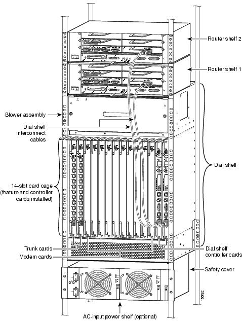
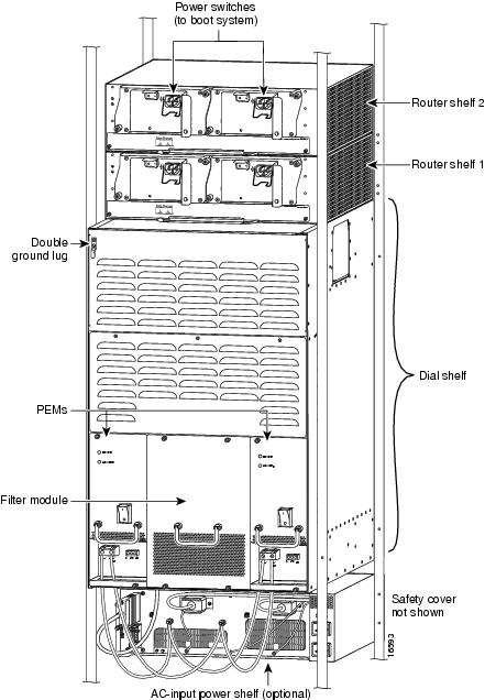
shows a front view of a fully configured Cisco AS5800 Universal Access Server with dual router shelves (split dial shelf). shows a rear view of the same system.
Figure 1 Cisco AS5800 Universal Access Server with Split Dial Shelf—Front View
Figure 2 Cisco AS5800 Universal Access Server with Split Dial Shelf—Rear View
Cisco 5814 Dial Shelf Overview
The Cisco AS5814 dial shelf contains 14 slots (numbered 0 through 13 on the backplane) and can support up to 10 modem cards, 2 T3 or 4 T1 trunk cards, and 2 DSCs. Slots 12 and 13 in the dial shelf are dedicated slots for the DSCs. Metal guard pins on the backplane module prevent you from installing any other type of card in these two slots. The modular chassis supports OIR and redundant power, and includes environmental monitoring and feedback control.
The dial shelf contains ingress interfaces (CT1/CE1 or CT3/CE3 Primary Rate Interfaces (PRI)) that terminate ISDN and modem calls, and break out individual calls from the appropriate telco services. Digital signal level 0 (DS0) or ISDN calls are terminated on the trunk card High-level Data Link Control (HDLC) controllers, and analog calls are sent to modem resources on the modem cards. As a result, any DS0 can be mapped to any HDLC controller or modem module. You can install multiple ingress interface cards of like or different types, which enables you to configure your systems as fully operative, port redundant, or card redundant, depending on your specific needs.
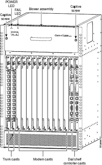
shows the Cisco AS5814 dial shelf fully loaded.
Figure 3 Cisco AS5814 Dial Shelf
Clock Management
The DSCs also provide clock and power control to the dial shelf feature cards. Each DSC contains a block of logic that is referred to as the common logic and system clocks. This block of logic can use a variety of sources to generate the system timing, including an E1/E3 or T1/T3 input signal from the BNC connector on the DSC's front panel.
Only one common logic is active at any one time, which is indicated by the clock (CLK) LED on the DSC's front panel. The active common logic is user selectable and is independent from each DSC. This assures that if a DSC needs replacing, or if the slave DSC becomes the master, clocking remains stable. The selected common logic should not be changed during normal operation, unless related hardware failure is suspected or diagnosed.
The configuration commands for the master clock specify the various clock sources and a priority for each source. Together these commands define a list, ordered by priority, of the clock sources used to generate the master clock. The prioritized list, configured on the router shelves, is passed to and stored by the DSC providing the active clock. In the event of failure of the highest priority clock source, the DSC switches to the source with the next highest priority.
With a split dial shelf, the clock sources can be configured on either of the router shelves. Typically a router configures clock sources only from the slots that it owns; clock sources from other slots can be configured, but they will be ignored. On the dial shelf, all valid clock source configurations need to be known to the DSC providing the clock, including the clock source configurations on the router connected to the other DSC.
In a typical Cisco AS5800 configuration (without a split dial shelf), clock source configuration lines that specify an external clock are sent directly from the router shelf to both DSCs. In the split dial shelf configuration a router can send the clock source configuration only to the DSC to which it is connected, not to both DSCs. If an external clock is used in a split dial shelf configuration, it must be configured identically on both router shelves and must be physically connected to both DSCs.
An error condition can arise if a clock input on one router is configured to have the same priority as a clock input configured on the other router. However, the command is not rejected since we may not know all the values configured on the other router. Warning messages are issued to both routers when this condition is detected. Two clock inputs specified with identical priorities will both go into the ordered list of clock sources, but the one received first by the DSC providing the active clock will be assigned a higher priority.
The show dial-shelf clocks command shows all configured clock sources, even those from non-owned trunk cards. There can be only one DSC providing the master clock; however, it may need to have backup clock sources configured from all trunk cards present (regardless of which DSC owns them).
Dial Shelf OIR Events
Each DSC needs to know whether it is to operate in split mode or normal mode, and in split mode it needs to know which slots are owned by its connected router. Currently the DSCs receive inventory messages from the router shelves, informing them which cards the routers think are present in the dial shelf. In split mode operation, these messages have been extended to inform the DSC which mode is current, and the set of slots it owns if it is in split mode.
Split dial shelf configurations are managed by having the slots that are owned by one router appearing as empty slots to the other router. A router shelf is informed of dial shelf OIR events by messages that are sent to the router shelf when a card is inserted in or removed from a slot. In the split dial shelf configuration, once a DSC is informed by the connected router which slots it owns, it sends messages only for dial shelf OIR events that occur in slots that the connected router shelf owns. The hub on each DSC is configured to ignore traffic from cards in non-owned slots.
Feature Board Bootup
When a feature board starts running, it sends a message to the DSC. The DSC checks if it is the master for that slot. In the split dial shelf mode, only the DSC whose connected router owns the slot containing the feature board will respond to the message. The feature board subsequently uses receive firmware and a bootstrap image from that DSC, and configures itself to communicate through that DSC's hub. The first time a router shelf sends an inventory response to the DSC, it includes a flag indicating that all feature boards should be reloaded. In the split mode the final feature board image is downloaded by each DSC from the router shelf that owns it.
Slot Ownership Arbitration
The DSCs communicate between themselves to determine which one is to be active, where "being active" implies being the master for all the feature board slots in the dial shelf. In the split mode, each DSC is the master for the set of feature boards in the slots owned by its connected router. Additional messages are used to indicate when the DSCs are in split mode, and what set of slots they control.
A DSC that is already in split mode simply advertises that it is in split mode and which slots it is claiming. When the second DSC receives an indication that the first DSC is in split mode, its behavior depends on the current configuration of its attached router.
•
•
Hub Redundancy
In normal mode, both DSCs are connected to the same router shelf. The active DSC monitors the status of its link to the router shelf and, in the event of link failure, requests the other DSC to take over. When operating in split mode, each DSC is connected to a different router shelf, so the DSCs do not send or respond to link failure messages. If one DSC's link fails, the other DSC cannot transparently take over.
TDM Resource Allocation
Trunk cards and modem cards are tied together across a time-division multiplexing (TDM) bus on the dial shelf backplane. Timeslots for the TDM bus are allocated on a call-by-call basis by the router shelf. This is implemented by initializing a queue, at start-up, with one element for each usable timeslot (currently 14*128 = 1792 timeslots are used). Timeslots are allocated for a call from the front of the queue, and replaced at the end of the queue when the call is completed. For split dial shelf operation timeslots are added to the queue dynamically as they are needed. When a TDM slot is required and the queue is empty, a chunk of TDM slots is allocated to the queue.
In normal mode, the router shelf connected to the DSC in slot 12 allocates timeslots starting from 0 going up, and the router shelf connected to the DSC in slot 13 allocates timeslots starting from 1791 going down. For split dial shelf operation each router is assigned half of the usable set of timeslots. The router shelf connected to the DSC in slot 12 controls the first half of the timeslots (0-895). The router shelf connected to the DSC in slot 13 controls the second half of the timeslots (896-1791).
Environmental Monitoring
In split mode, environmental monitoring for the full dial shelf is carried out by both DSCs. This means that warnings about overheating cards go to both router shelves, regardless of which one owns the card (or even if neither claims ownership of the card). By having the warnings go to both routers, the chance of an environmental problem going unreported is reduced.
Cisco 7206 Router Overview
This section provides physical and functional overviews of the Cisco 7206 router shelves. It contains physical descriptions of the router hardware and major components, and functional descriptions of hardware-related features.
The Cisco 7206 router supports call signaling for PRI interfaces, packet processing, and multiprotocol, multimedia routing and bridging with all commonly used high-speed LAN and WAN interfaces including Ethernet, Fast Ethernet (FE), Asynchronous Transfer Mode (ATM), High-Speed Serial Interface (HSSI), and Fiber Distributed Data Interface (FDDI).
The Cisco 7206 router shelf handles upper layer routing tasks, and provides the following features:
•
•
•
•
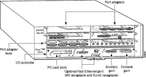
shows the significant Cisco 7206 router components.
Figure 4 Cisco 7206 Router Components
Note
Network Interfaces
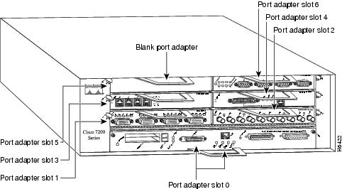
Network interfaces reside on port adapters that provide the connection between the router's three Peripheral Component Interconnect (PCI) buses and external networks. The Cisco 7206 has six slots (slot 1 through slot 6) for the port adapters, one slot for an Input/Output (I/O) controller, and one slot for a network processing engine (NPE). You can place port adapters in any of the six available slots.
The front of the Cisco 7206 provides access to an I/O controller and up to six network interface port adapters. The I/O controller contains the following:
•
•
•
Note
The port adapters installed in the Cisco 7206 router are of the same type as those installed on the second-generation Versatile Interface Processors (VIP2s) in the Cisco 7500 series routers, in Cisco 7000 series routers using the Cisco 7000 series Route Switch Processor (RSP7000) and Cisco 7000 series Chassis Interface (RSP7000CI), and in the Cisco uBR7246 universal broadband router. The port adapters installed in the Cisco 7206 support OIR. For an explanation of OIR, see the "Online Insertion and Removal" section.
Note
Port adapter slots in the Cisco 7206 routers are numbered from left to right from the bottom up, beginning with port adapter slot 1 and continuing through port adapter slot 6. Port adapter slot 0 is the Fast Ethernet port on the I/O controller. See .
Figure 5 Port Adapter Slot Numbering
Power Supplies
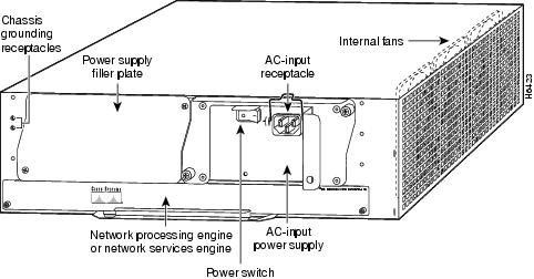
The Cisco 7206 router comes equipped with one 280W AC-input or one 280W DC-input power supply. A fully configured Cisco 7206 router operates with only one installed power supply; however, a second, optional power supply of the same type provides hot-swappable, load-sharing, redundant power. shows the rear of a Cisco 7206 router configured with a single AC-input power supply. (A power supply filler plate is installed over the second power supply bay.)
Caution
The power supply has the router's main power switch and either an AC-input power receptacle or a hardwired DC-input power cable (depending on the type of installed power supply). The rear of the Cisco 7206 router provides access to the network processing engine and the power supplies. Adjacent to the power supply bays there are two chassis ground receptacles that provide a chassis ground connection for ESD equipment or a two-hole grounding lug. See .
Figure 6 Cisco 7206 Router—Rear View
Three internal fans draw cooling air into chassis and across internal components to maintain an acceptable operating temperature. The three fans are enclosed in a tray that is located in the subchassis.
Caution
Network Processing Engine
The network processing engine has no external connectors or LEDs. There is a handle for removing and installing the network processing engine and two captive screws for securing it to the chassis.
Note
The Midplane
The I/O controller, port adapters, power supplies, and network processing engine slide into their respective chassis slots and connect directly to the router's midplane; there are no internal cables to connect. The midplane distributes DC power from the power supplies to the I/O controller, port adapters, fan tray, and network processing engine.
The midplane also identifies OIR of the port adapters, bridges the PCI buses from the port adapters to packet static random-access memory (SRAM) on the network processing engine, arbitrates traffic across the PCI buses, and generates the clock signals for the port adapters on each PCI bus.
Rack-Mount Kit
A rack-mount kit is standard equipment included with all Cisco 7206 routers when they are shipped from the factory. The kit provides the hardware needed to mount the router in a standard 19-inch equipment rack or a telco rack. Steps for installing the Cisco 7206 router in an equipment rack are explained in the chapter "Installing the Cisco 7206" in the Cisco 7206 Installation and Configuration Guide (Document Number DOC-7206-ICG=).
A fully configured Cisco 7206, with two installed power supplies and all chassis slots filled, weighs approximately 50 pounds (22.7 kilograms [kg]). For clearance requirements and rack-mount installation considerations, refer to the section "Site Environment" in the chapter "Preparing for Installation" in the Cisco 7206 Installation and Configuration Guide (Document Number DOC-7206-ICG=).
Field-Replaceable Units
The Cisco 7206 router is easy to service; all its major components are field replaceable units (FRUs). Instructions for removing and replacing individual FRUs are contained in separate documents called configuration notes, which accompany every FRU shipped from the factory. The configuration notes are also available on the Documentation CD-ROM and on Cisco Connection Online (CCO).
The following Cisco 7206 components are FRUs:
•
Detailed instructions for removing and replacing the network processing engine are contained in the configuration note Network Processing Engine Replacement Instructions (Part Number 78-3225-xx).
•
Detailed instructions for removing and replacing the I/O controller are contained in the configuration note Input/Output Controller Replacement Instructions (Part Number 78-3224-xx).
•
The Cisco 7206 is shipped from the factory with up to six installed port adapters that provide a variety of network media types (based on your order). The port adapters connect directly to the router's midplane. Port adapters installed in the Cisco 7206 router support OIR.
Detailed instructions for removing, replacing, and configuring the port adapter types supported by the Cisco 7206 are contained in the configuration note for that port adapter. For example, if you plan to replace a 4-port, half-duplex Token Ring port adapter in your Cisco 7206 router, refer the configuration note PA-4R Token Ring Port Adapter Installation and Configuration (Part Number 78-2661-xx).
For general instructions about how to remove and replace a port adapter, refer to the section "Replacing a Port Adapter" in the chapter "Maintaining the Cisco 7206" in the Cisco 7206 Installation and Configuration Guide (Document Number DOC-7206-ICG=).
•
Detailed instructions for removing and replacing the Cisco 7206 power supplies are contained in the configuration notes 280-Watt AC-Input Power Supply Replacement Instructions (Part Number 78-3227-xx) and 280-Watt DC-Input Power Supply Replacement Instructions (Part Number 78-3420-xx).
•
Detailed instructions for removing and replacing the fan tray are contained in the configuration note Subchassis and Fan Tray Replacement Instructions (Part Number 78-3228-xx).
•
Detailed instructions for removing and replacing subchassis are contained in the configuration note Subchassis and Fan Tray Replacement Instructions (Part Number 78-3228-xx).
•
To replace the chassis you must remove all internal components; therefore, when replacing the chassis, refer to the individual configuration notes that explain how to remove and replace each internal component.
•
Detailed instructions for removing and replacing Flash memory cards and SIMMs are contained in the configuration note Memory Replacement Instructions for the Network Processing Engine and Input/Output Controller (Part Number 78-3226-xx).
Instructions for installing and removing a Flash memory card are also contained in the section "Installing and Removing a Flash Memory Card" in the chapter "Maintaining the Cisco 7206" of the Cisco 7206 Installation and Configuration Guide (Document Number DOC-7206-ICG=).
•
For detailed instructions about how to install the rack-mount and cable-management brackets on your Cisco 7206, refer to the sections "Rack-Mounting the Cisco 7206" and "General Installation" in the chapter "Installing the Cisco 7206" in the Cisco 7206 Installation and Configuration Guide (Document Number DOC-7206-ICG=).
Dial Shelf Interconnect Port Adapter Overview
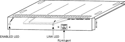
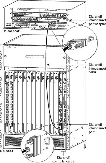
The router shelf contains a dial shelf interconnect port adapter (see ) with a single RJ-45 receptacle, which is used to connect a router shelf to a DSC card in the Cisco AS5814 dial shelf. The interconnect port adapter installs in any 7206 router shelf port adapter slot and connects directly to the DSC on the dial shelf via a single dial shelf interconnect cable (DSIC). These nonblocking interconnect cables support 100-Mbps full-duplex data transfer.
Data is converted into packets by the feature cards, transmitted to a hub on a DSC, then sent to the dial shelf interconnect port adapter on the router shelf. Conversely, packets from the router shelves are sent to the DSCs, where they are transmitted over the backplane to the modem and trunk cards.
Figure 7 Dial Shelf Interconnect Port Adapter
Dial Shelf Interconnect Cable
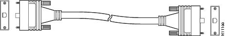
The dial shelf interconnect port adapter includes a Cisco proprietary dial shelf interconnect cable (DSIC) (see .), customized with jackscrews on each end to ensure that the connection is not inadvertently interrupted. You should use this specially designed cable that shipped with your dial shelf interconnect port adapter to connect the DSC to the router shelf.
Warning
Caution
Figure 8 Dial Shelf Interconnect Cable
Table 1 RJ-45 Receptacle Pinout
Note
The instructions for connecting the cables for other types of port adapters installed in the Cisco 7206 are contained in the respective configuration notes for each port adapter. These configuration notes accompany every port adapter that is shipped from the factory as an installed item in a Cisco 7206 or as a FRU. These documents are also available on the Cisco Connection Documentation CD-ROM and on Cisco Connection Online (CCO).
Safety Guidelines
This section provides safety and ESD-prevention guidelines to help you avoid injury to yourself and avoid damage to the equipment. Cisco recommends the following safety guidelines when working with equipment that connects to electrical power or telephone wiring:
•
•
•
•
•
•
Preventing Electrostatic Discharge Damage
Electrostatic discharge (ESD) damages equipment and impairs electrical circuitry. ESD occurs when printed circuit boards are improperly handled and results in complete or intermittent failures.
The system feature cards and dual router shelves consist of a printed circuit board that is fixed in a metal carrier. Electromagnetic interference (EMI) shielding, connectors, and a handle are integral components of the carrier. Handle the system feature cards and dual router shelves by their carrier edges and handle only; never touch the printed circuit board components or connector pins.
Although the metal carrier helps to protect the printed circuit boards from ESD, wear a preventive antistatic strap whenever handling the dial shelf feature cards, dual router shelves, router shelf network processing engine, I/O controller, or port adapters. Ensure that the strap makes good skin contact and connect the strap's clip to an unpainted chassis surface to safely channel unwanted ESD voltages to ground.
If no wrist strap is available, ground yourself by touching the metal part of the chassis.
Cisco recommends the following guidelines to prevent ESD damage:
•
•
•
Caution
Safety Warnings
Safety warnings appear throughout this publication in procedures that, if performed incorrectly, may harm you. A warning symbol precedes each warning statement.
Warning
Waarschuwing Dit waarschuwingssymbool betekent gevaar. U verkeert in een situatie die lichamelijk letsel kan veroorzaken. Voordat u aan enige apparatuur gaat werken, dient u zich bewust te zijn van de bij elektrische schakelingen betrokken risico's en dient u op de hoogte te zijn van standaard maatregelen om ongelukken te voorkomen. Voor vertalingen van de waarschuwingen die in deze publicatie verschijnen, kunt u het document Regulatory Compliance and Safety Information (Informatie over naleving van veiligheids- en andere voorschriften) raadplegen dat bij dit toestel is ingesloten.
Varoitus Tämä varoitusmerkki merkitsee vaaraa. Olet tilanteessa, joka voi johtaa ruumiinvammaan. Ennen kuin työskentelet minkään laitteiston parissa, ota selvää sähkökytkentöihin liittyvistä vaaroista ja tavanomaisista onnettomuuksien ehkäisykeinoista. Tässä julkaisussa esiintyvien varoitusten käännökset löydät laitteen mukana olevasta Regulatory Compliance and Safety Information -kirjasesta (määräysten noudattaminen ja tietoa turvallisuudesta).
Attention Ce symbole d'avertissement indique un danger. Vous vous trouvez dans une situation pouvant causer des blessures ou des dommages corporels. Avant de travailler sur un équipement, soyez conscient des dangers posés par les circuits électriques et familiarisez-vous avec les procédures couramment utilisées pour éviter les accidents. Pour prendre connaissance des traductions d'avertissements figurant dans cette publication, consultez le document Regulatory Compliance and Safety Information (Conformité aux règlements et consignes de sécurité) qui accompagne cet appareil.
Warnung Dieses Warnsymbol bedeutet Gefahr. Sie befinden sich in einer Situation, die zu einer Körperverletzung führen könnte. Bevor Sie mit der Arbeit an irgendeinem Gerät beginnen, seien Sie sich der mit elektrischen Stromkreisen verbundenen Gefahren und der Standardpraktiken zur Vermeidung von Unfällen bewußt. Übersetzungen der in dieser Veröffentlichung enthaltenen Warnhinweise finden Sie im Dokument Regulatory Compliance and Safety Information (Informationen zu behördlichen Vorschriften und Sicherheit), das zusammen mit diesem Gerät geliefert wurde.
Avvertenza Questo simbolo di avvertenza indica un pericolo. La situazione potrebbe causare infortuni alle persone. Prima di lavorare su qualsiasi apparecchiatura, occorre conoscere i pericoli relativi ai circuiti elettrici ed essere al corrente delle pratiche standard per la prevenzione di incidenti. La traduzione delle avvertenze riportate in questa pubblicazione si trova nel documento Regulatory Compliance and Safety Information (Conformità alle norme e informazioni sulla sicurezza) che accompagna questo dispositivo.
Advarsel Dette varselsymbolet betyr fare. Du befinner deg i en situasjon som kan føre til personskade. Før du utfører arbeid på utstyr, må du vare oppmerksom på de faremomentene som elektriske kretser innebærer, samt gjøre deg kjent med vanlig praksis når det gjelder å unngå ulykker. Hvis du vil se oversettelser av de advarslene som finnes i denne publikasjonen, kan du se i dokumentet Regulatory Compliance and Safety Information (Overholdelse av forskrifter og sikkerhetsinformasjon) som ble levert med denne enheten.
Aviso Este símbolo de aviso indica perigo. Encontra-se numa situação que lhe poderá causar danos físicos. Antes de começar a trabalhar com qualquer equipamento, familiarize-se com os perigos relacionados com circuitos eléctricos, e com quaisquer práticas comuns que possam prevenir possíveis acidentes. Para ver as traduções dos avisos que constam desta publicação, consulte o documento Regulatory Compliance and Safety Information (Informação de Segurança e Disposições Reguladoras) que acompanha este dispositivo.
¡Advertencia! Este símbolo de aviso significa peligro. Existe riesgo para su integridad física. Antes de manipular cualquier equipo, considerar los riesgos que entraña la corriente eléctrica y familiarizarse con los procedimientos estándar de prevención de accidentes. Para ver una traducción de las advertencias que aparecen en esta publicación, consultar el documento titulado Regulatory Compliance and Safety Information (Información sobre seguridad y conformidad con las disposiciones reglamentarias) que se acompaña con este dispositivo.
Varning! Denna varningssymbol signalerar fara. Du befinner dig i en situation som kan leda till personskada. Innan du utför arbete på någon utrustning måste du vara medveten om farorna med elkretsar och känna till vanligt förfarande för att förebygga skador. Se förklaringar av de varningar som förkommer i denna publikation i dokumentet Regulatory Compliance and Safety Information (Efterrättelse av föreskrifter och säkerhetsinformation), vilket medföljer denna anordning.
Online Insertion and Removal
All port adapters in the Cisco 7206 router also support OIR. OIR functionality allows you to add, remove, or replace port adapters while the system is operating; you do not need to notify the software or shut down the system power. This provides a method that is seamless to end users, maintains all routing information, and ensures session preservation. For specific procedures for installing and replacing a port adapter in a Cisco 7206 router, refer to the appropriate port adapter configuration note.
Caution
Tools and Parts Required
Your Cisco 7206 chassis is fully assembled at the factory; no assembly is required. However, you will need the following tools and equipment to remove and replace the router chassis. If you need additional equipment, contact a service representative for ordering information.
•
•
•
•
In addition, you might need the following external equipment:
•
•
•
Several T1 CSU/DSU devices are available as additional equipment, and most provide either a V.35, EIA/TIA-449, or EIA-530 electrical interface.
•
•
•
Ensuring Easy System Access
If your Cisco AS5800 Universal Access Server is installed in a standard 19-inch, 4-post rack or standard telco rack, cables from other equipment in the rack might obstruct access to the rear of the system. Rack power strips or other permanent fixtures might also cause obstruction.
To ensure easy system access when the Cisco AS5800 Universal Access Server is installed in a rack:
•
•
Removing a Router Shelf
Warning
Warning
Caution
Caution
To remove the Cisco 7206 router shelf, complete the following steps:
Step 1
Step 2
Caution
Note
Step 3
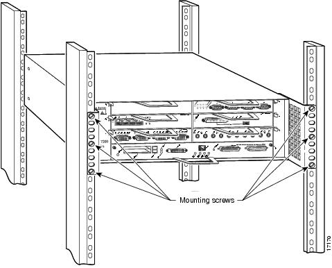
If you rack-mounted the Cisco 7206 router from the rear, the rack mount brackets are installed at the rear of the chassis. You must remove the mounting screws from both brackets before you can remove the chassis from the rack.
Warning
Figure 9 Removing the Mounting Screws
Step 4
This completes the procedure for removing the chassis from the rack.
Replacing a Router Shelf
Warning
Caution
Caution
For detailed instructions about how to replace the Cisco 7206, refer to the chapter "Installing the Cisco 7206" in the Cisco 7206 Installation and Configuration Guide (Document Number DOC-7206-ICG=).
Connecting the Cables
To connect the dial shelf interconnect cables, complete the following steps:
Warning
Step 1
Step 2
Step 3
Step 4
Step 5
Caution
Figure 10 Connecting the Dial Shelf Interconnect Cables
Warning
For more information about the dial shelf interconnect cable and dial shelf interconnect port adapter, refer to the document Cisco AS5800 Universal Access Server Dial Shelf Interconnect Port Adapter Installation and Replacement (Part Number 78-4663-xx).
Installing and Removing Flash Memory Cards
Both the router shelf and the dial shelf contain PCMCIA slots for inserting Flash memory cards. The router shelf PCMCIA slots are located on the I/O controller and are oriented horizontally; the dial shelf PCMCIA slots are located on the DSC and are oriented vertically. Except for the orientation of the slots, the installation procedures are the same for both shelves.
This section describes inserting and removing a Flash memory card in a router shelf. For procedures specific to the dial shelf, refer to the Cisco AS5800 Access Server Hardware Installation and Configuration Guide (Document Number DOC-AS5800-HICG=) that shipped with your dial shelf.
Note
Installing a Flash Memory Card
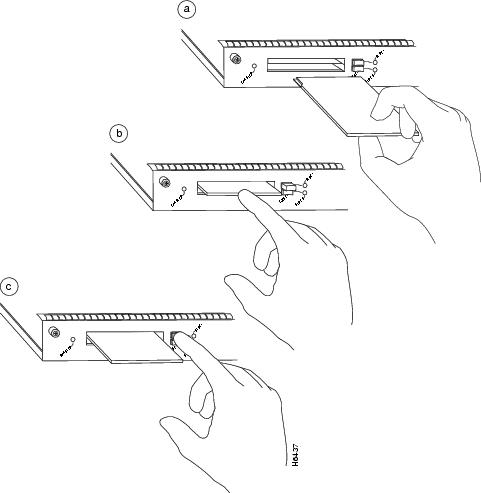
The I/O controller has two PCMCIA slots for Flash memory cards: slot 0 (lower) and slot 1 (upper). Complete the following steps to insert a Flash memory card in either PCMCIA slot:
Step 1
Step 2
Note
Removing a Flash Memory Card
To remove a Flash memory card from either PCMCIA slot, complete the following steps:
Step 1
Step 2
Step 3
This completes the steps for inserting and removing a Flash memory card.
This completes the router shelf and Flash memory installation procedures. If you have any questions or need assistance, proceed to the "Cisco Connection Online" section.
Figure 11 Inserting and Removing a PCMCIA Flash Memory Card
Starting the Cisco 7206
After installing your Cisco 7206 and connecting the cables, start each router as follows:
Step 1
•
•
•
•
•
•
Step 2
Step 3
Step 4
Step 5
Cisco Internetwork Operating System SoftwareIOS (tm) 7200 Software (C7200-J-M), Version 11.3(6.3)AACopyright (c) 1986-1998 by cisco Systems, Inc.Compiled Sun 21-Oct-98 04:10 by ...
Note
Step 6
--- System Configuration Dialog ---At any point you may enter a questions mark '?' for help. Use ctrl-c to abort configuration dialog at any prompt. Default settings are in square brackets '[]'.Continue with configuration dialog? [yes]:You have the option of proceeding with the setup command facility to configure the interfaces, or exiting from setup and using configuration commands to configure global (system-wide) and interface-specific parameters. You do not have to configure the interfaces immediately; however, you cannot enable the interfaces or connect them to any networks until you have configured them.
Many of the port adapter LEDs will not go on until you have configured the interfaces. To verify correct operation of each interface, complete the first-time start-up procedures and configuration, then refer to the configuration note for each port adapter for LED descriptions and to check the status of the interfaces.
Commands for Split Dial Shelf Systems
The split mode is intended to support two router shelves connected to a single dial shelf. To use this arrangement as intended, both router shelves should have split dial shelf configured. However, a second router is not required; a single router can run in split mode with all slots owned by that router.
Split Dial Shelf Configuration
Split dial shelf configuration is implemented by connecting two router shelves to a single dial shelf. You allocate the slots in the dial shelf between the two router shelves to achieve the desired configuration. The two router shelves are both configured to run in split mode by means of a new top level router configuration command:
dial-shelf split slots {slot-numbers}
where slot-numbers is a list of the dial shelf slot numbers (from 0 through 11) that the router owns, with the slot numbers separated by spaces. Slot ownership for each of the two router shelves is configured individually using the dial-shelf split slots command.
•
•
•
When you configure a Cisco AS5800 system to operate in split mode, it is the same as having two Cisco AS5800 systems with each having a separate set of feature boards assigned to its router; they just happen to be sharing a single dial shelf. Modem pooling, for example, is the same as if you had two separate Cisco AS5800 systems. Router shelf 1 has a modem pool that consists of all the modem cards that reside in slots owned by router shelf 1. The same situation applies to router shelf 2.
Changing to Split Mode
This section describes the procedure required to transition a router from normal mode to split mode, and changing the set of slots a router owns while it is in split mode. Since the process of switching the ownership of a slot from one router to the other is potentially disruptive (when a feature board is restarted, all calls through that card are lost), a router shelf cannot take over a slot until ownership is relinquished by the router that currently claims ownership, either by reconfiguring the router or disconnecting that router or its associated DSC.
The dial shelf is split by dividing the ownership of the feature boards between the two router shelves. You must configure the division of the dial shelf slots between the two router shelves so that each router controls an appropriate mix of trunk and modem cards. Each router shelf controls its set of feature boards as if those were the only boards present. There is no interaction between feature boards owned by one router and feature boards owned by the other router.
Split mode is entered when the dial-shelf split slots command is parsed on the router shelf. This can occur when the router is starting up and parsing the stored configuration, or when the command is entered when the router is already up. On parsing the dial-shelf split slots command, the router frees any resources associated with cards in the slots that it no longer owns, as specified by exclusion of slot numbers from the slot-numbers argument. The router should be in the same state as if the card had been removed from the slot; all calls through that card will be terminated. The configured router then informs its connected DSC that it is in split mode, and which slots it claims to own.
In split mode, a router shelf uses only half of the 1,792 available TDM timeslots. (See the "TDM Resource Allocation" section.) If a dial-shelf split slots command is entered when the total calls using timeslots exceeds the number that would normally be available to the router in split mode, the command is rejected. This should occur only when a change to split mode is attempted where the dial shelf has more than 896 calls in progress (more than half of the 1,792 available timeslots). Otherwise, a transition from normal mode to split mode can be made without disturbing the cards in the slots that remain owned, and calls going through those cards will stay up.
Transition Procedure
To transition from normal mode to split mode, complete the following steps:
Step 1
Having the same version of IOS running on both DSCs and both router shelves is not mandatory; however, it is a good idea. There is no automatic checking that the versions are the same.
Step 2
The entire procedure for transitioning from normal mode to split mode should require approximately one hour if all the hardware is already installed.
Step 3
Step 4
Enter the dial-shelf split slots {slot-numbers} command, specifying the slot numbers that are to be owned by the existing router shelf.
Step 5
Enter the dial-shelf split slots {slot-numbers} command, specifying the slot numbers that are to be owned by the new router shelf. Do not specify any of the slot numbers that you specified in Step 4. The range of valid slot numbers is 0 through 11.
Step 6
Step 7
Step 8
Enter the show dial-shelf command for each router. This command has been extended so that the response indicates that the router shelf is running in split mode and which slots the router shelf owns. The status of any cards in any owned slots is shown, just as they are in the present show dial-shelf command.
Step 9
Changing Slot Sets
You can change the sets of slots owned by the two router shelves while they are in split mode by first removing slot(s) from the set owned by one router, then adding them to the slot set of the other router. The changed slot set information is sent to the respective DSCs, and the DSCs determine which slots have been removed and which added from the new slot set information. It should be clear that moving a slot in this manner will disconnect all calls that were going through the card in that slot.
To move a slot from one router shelf's control to the others, the router releasing the slot should be modified first by entering the dial-shelf split slots remove command, specifying the slot numbers to be released. The released slot(s) can then be added to the slot set of the other router by re-entering the dial-shelf split slots command including the new slot number(s).
•
The router shelf that is losing the slot frees any resources and clears any state associated with the card in the slot it is relinquishing. The DSC reconfigures its hub to ignore traffic from that slot, and if there is a card in the slot it will be reset. This ensures that the card frees up any TDM resource it might be using, and allows it to restart under control of the router shelf that is subsequently configured to own the slot.
•
If there are no configuration conflicts, and there is a card present in the added slot, a dial-shelf OIR insertion event is sent to the router shelf, which processes the event the same as it always does. The card in the added slot is reset by the DSC to ensure a clean state, and the card downloads its image from the router shelf that now owns it.
If the other router shelf (and the other DSC) claim ownership of the same slot, the command adding the slot should be rejected. However, should a configuration conflict exist, error messages are sent to both routers and the card is not reset until one of the other router shelves and its DSC stop claiming ownership of the slot. Normally, this will not happen until you issue a dial-shelf split slots remove command surrendering the ownership claim on the slot by one of the routers.
Leaving Split Mode
Split mode is exited when the dial shelf configuration is changed by a no dial-shelf split slots command. When the split dial shelf line is removed, the router shelf will start using all of the TDM timeslots. Feature boards that were not owned in split mode, and are not owned by the other router, will be reset. Cards in slots that are owned by the other router will be reset, but only after the other DSC has been removed or is no longer claiming the slots. The split dial shelf configuration should not be removed while the second router shelf is still connected to the dial shelf.
When a router configured in split mode fails, all calls associated with the failed router are lost. Users cannot connect back in until the failed router recovers and is available to accept new incoming calls; however, the other split mode router shelf will continue to operate normally.
Potential Problems
The system will behave as configured as soon as the configuration is changed. The exception is when there is a misconfiguration, such as one router is configured in split mode and the other router is configured in normal mode, or both routers are configured in split mode and both claim ownership of the same slot(s).
Problems can arise if one of the two routers connected to a dial shelf is not configured in split mode, or if both are configured in split mode and both claim ownership of the same slot(s). If the state of the second router is known when the dial-shelf split slots command is entered and the command would result in a conflict, the command is rejected.
If a conflict in slot ownership does arise, both routers will receive warning messages until the conflict is resolved. Any card in a slot which is claimed by both routers remains under the control of the router that claimed it first, until you can resolve the conflict by correcting the configuration of one or both routers.
It should be noted that there can also be slots that are not owned by either router (orphan slots). Cards in orphan slots cannot boot up until one of the two routers claims ownership of the slot because neither DSC will download bootstrap images to cards in unowned orphan slots.
Show Commands
In normal mode, all show commands will look and behave as they do in the current system. In split mode, most show commands will look and behave as they would in the current system if there were no cards in the slots for which the other router has configured ownership. This is consistent with the view of a split dial shelf configuration being basically two separate Cisco AS5800 systems. A router shelf cannot manage, or even know the state of, any cards in slots that it does not own. For example, DSIP console and execute-on commands work only on owned slots.
There are, however, a few exceptions:
•
•
When in split mode, the show dial-shelf output is extended as in the following example:
pinetopRS#sh dial-shelfSystem is in split dial shelf mode.Slots owned: 0 2 3 4 5 6 (connected to DSC in slot 13)Slot Board CPU DRAM I/O Memory State ElapsedType Util Total (free) Total (free) Time0 CE1 0%/0% 21341728( 87%) 8388608( 45%) Up 01:11:372 CE1 0%/0% 21341728( 87%) 8388608( 45%) Up 01:11:374 Modem(HMM) 20%/20% 6661664( 47%) 6291456( 33%) Up 01:11:375 Modem(DMM) 0%/0% 6661664( 31%) 6291456( 32%) Up 01:11:376 Modem(DMM) 0%/0% 6661664( 31%) 6291456( 32%) Up 01:11:3713 DSC 0%/0% 20451808( 91%) 8388608( 66%) Up 01:16:31Dial shelf set for auto bootNote only the first two lines of output are new, the remaining information is exactly the same as in the existing system if there were no cards in the slots that are not owned (1 and 7 through 12).
•
pinetopRS#sh dial-shelf splitSystem is in split dial shelf mode, connected to DSC in slot 13.Slots owned: 0 2 3 4 5 6Non owned slots:Slot Board Type1 CE17 Modem(DMM)8 Modem(DMM)9 Modem(DMM)10 Slot Empty11 Slot Empty12 DSCNote that the show dial-shelf split command also shows the slots and corresponding feature boards for orphan slots (those slots not owned by either router shelf). This means that OIR events on all slots in the dial shelf are detected by both DSCs and the feature boards are added to or deleted from the list of boards physically present in the dial shelf. When a feature board is inserted into an orphan slot, a message is sent to both router shelves indicating that a feature board was just inserted. This message is different than an OIR event message—OIR event processing is done only for owned slots.
•
Managing a Split Dial Shelf
If you are installing split dial shelf systems, a system controller is available that provides a single system view of multiple POPs. The system controller for the Cisco AS5800 Universal Access Server includes the Cisco 3640 router running Cisco IOS software. The system controller can be installed at a remote facility so that you can access multiple systems through a console port or Web interface.
There are no new Management Information Bases (MIBs) or MIB variables required for the split dial shelf configuration. A split dial shelf appears to Simple Network Management Protocol (SNMP) management applications as two separate Cisco AS5800 systems. One console to manage the whole system is not supported—you must have a console session per router shelf (two console sessions) to configure each split of the Cisco AS5800. The system controller must manage a split dial shelf configuration as two separate Cisco AS5800 systems.
The normal mode configuration of the Cisco AS5800 requires the dial shelf and router shelf IDs to be different. In a split system, four unique shelf IDs are desirable; one for each router shelf and one for each of the slot sets; however, a split system will function satisfactorily if the router shelf IDs are the same. If a system controller is used to manage a split dial shelf configuration, then the two routers must have distinct shelf IDs, just as they must when each router has its own dial shelf.
You can download software configurations to any Cisco AS5800 using SNMP or a Telnet connection. The system controller also provides performance monitoring and accounting data collection and logging.
In addition to the system controller, a network management system with a graphical user interface (GUI) runs on a UNIX SPARC station and includes a database management system, polling engine, trap management, and map integration.
Configuring the Routers
To configure a router for split dial shelf operation, complete the following steps:
The following additional commands have been added to support split dial shelf systems:
If the system does not complete each of the steps in the start-up procedure, proceed to the "Verifying and Troubleshooting the Installation" section for troubleshooting recommendations and procedures.
Error Messages
New error messages for various split dial shelf conditions include:
Error Message    Duplicate priority clock source configured on other router
shelf.
Explanation The configuration commands for the master clock specify the clock sources and a priority for each source. Together these commands define a prioritized list of the clock sources used to generate the master clock. This list, configured on the router shelf, is passed to and stored by the DSC providing the active clock. In the event of failure of the highest priority clock source, the DSC switches to the source with the next highest priority.
With a split dial shelf, clock sources can be configured on either of the router shelves from the slots that each shelf owns. On the dial shelf, all valid clock source configurations are known to the DSC providing the clock, including the clock source configurations on the other router/DSC.
This error condition results when a clock input on one router is configured to have the same priority as one configured on the other router. The original configuration command is not rejected; however, these error messages are issued to both routers when a duplicate priority condition is detected. The two clock inputs specified with identical priorities both go into the ordered list of clock sources, but the one received first by the DSC providing the active clock is assigned a higher priority.
Recommended Action Reconfigure the clock sources on the two routers so that they have different priorities.
Error Message Other router shelf is in split mode when this one is not.Explanation The split mode is intended to support two router shelves connected to a single dial shelf. To use this arrangement, both connected router shelves should have split dial shelf configured. Problems can arise if there are two routers connected to the dial shelf, but one router is not configured in split mode.
Recommended Action Issue a dial-shelf split slots command to this router or a no-dial-shelf split slots command to the other router; however, there's no point in having a second router shelf unless both routers are in split mode.
Error Message Other router shelf is not in split mode when this one is.Explanation The split mode is intended to support two router shelves connected to a single dial shelf. To use this arrangement, both connected router shelves should have split dial shelf configured. Problems can arise if there are two routers connected to the dial shelf, but one router is not configured in split mode.
Recommended Action Issue a dial-shelf split slots command to the other router or a no-dial-shelf split slots command to this router; however, there's no point in having a second router shelf unless both routers are in split mode.
Error Message    Other router shelf has overlapping slot ownership specified
in its split dial shelf configuration.
Explanation Each router shelf connects to one of the DSCs in the dial shelf. The dial shelf feature boards are divided between the two router shelves. Each router controls its own set of feature boards as if those were the only boards present—there is no interaction between feature boards owned by one router and feature boards owned by the other router, or with the other router.
This error message was issued because both routers are configured in split mode, but there is an overlap in the set of slots each router claims. While the conflict in slot ownership continues, both router shelves will periodically receive this error message.
Recommended Action Correct the configuration of one of the routers by issuing a dial-shelf split slots command with a list of slot numbers that does not include the slot that is reporting overlapping ownership. You must configure the division of the dial shelf slots between the two router shelves so that each router controls an appropriate mix of trunk and modem cards. Any card in a slot that is claimed by both routers will remain under the control of the router that claimed it first until you resolve the conflict by correcting the configuration.
Verifying and Troubleshooting the Installation
Your Cisco 7206 routers went through extensive testing before leaving the factory. However, if you encounter problems starting the routers, use the information in the chapter "Troubleshooting the Installation" in the Cisco 7206 Installation and Configuration Guide (Document Number DOC-7206-ICG=) to help isolate the cause of the problems. Make sure to review the safety warnings listed in the publication Regulatory Compliance and Safety Information for the Cisco 7200 Series Routers (Part Number 78-3419-xx) that accompanied your Cisco 7206 before using troubleshooting procedures.
If you are unable to easily solve the problem, contact a customer service representative for assistance and further instructions. Be prepared to provide the representative with the following information:
•
•
•
•
•
•
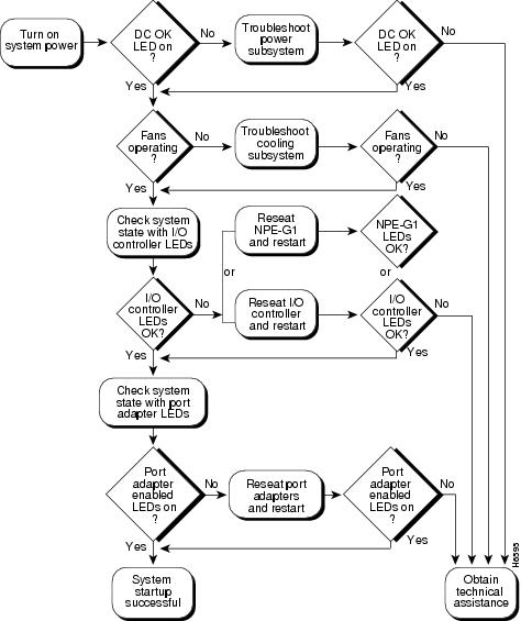
shows the general troubleshooting strategy for Cisco 7206 routers. Refer to this chart, as necessary, to isolate problems to a specific subsystem; then resolve the problem if possible.
Problem Solving with Subsystems
The key to solving problems with the system is isolating the problem to a specific subsystem. The first step in solving start-up problems is to compare what the system is doing to what it should be doing. Because a start-up problem is usually caused by a single component, it is more efficient to first isolate the problem to a subsystem rather than troubleshoot each component in the system. For these troubleshooting procedures, consider the following subsystems:
•
•
•
You can quickly verify that your new router shelf is properly installed and operative by observing the router LEDs as described in the "Starting the Cisco 7206" section."
Figure 12 Troubleshooting Strategy for Start-Up Problems
FCC Compliance
Regulatory compliance and safety information for the Cisco AS5800 Universal Access Server is contained in the Regulatory Compliance and Safety Information document that shipped with your system.
Cisco Connection Online
Cisco Connection Online (CCO) is Cisco Systems' primary, real-time support channel. Maintenance customers and partners can self-register on CCO to obtain additional content and services.
Available 24 hours a day, seven days a week, CCO provides a wealth of standard and value-added services to Cisco's customers and business partners. CCO services include product information, software updates, release notes, technical tips, the Bug Navigator, configuration notes, brochures, descriptions of service offerings, and download access to public and authorized files.
CCO serves a wide variety of users through two interfaces that are updated and enhanced simultaneously—a character-based version and a multimedia version that resides on the World Wide Web (WWW). The character-based CCO supports Zmodem, Kermit, Xmodem, FTP, and Internet e-mail, and is excellent for quick access to information over lower bandwidths. The WWW version of CCO provides richly formatted documents with photographs, figures, graphics, and video, as well as hyperlinks to related information.
You can access CCO in the following ways:
•
•
•
•
•
For a copy of CCO's Frequently Asked Questions (FAQ), contact cco-help@cisco.com. For additional information, contact cco-team@cisco.com.
Note
78-6289-01