 Feedback Feedback
|
Table Of Contents
Cisco AS5800 Universal Access Server Dial Shelf Controller Card Installation and Replacement
Cisco AS5800 Universal Access Server Overview
Dial Shelf Controller Card Overview
LED Indicators and Alarm Buttons
Preventing Electrostatic Discharge Damage
Removing and Replacing a Dial Shelf Controller Card
Removing a Dial Shelf Controller Card
Replacing a Dial Shelf Controller Card
Attaching the Dial Shelf Interconnect Cable
Verifying and Troubleshooting the Installation
Configuring the Dial Shelf Controller Card
Commands for Dual DSC Equipped Systems
Installing and Removing a Flash Memory Card
Installing a Flash Memory Card
Cisco AS5800 Universal Access Server Dial Shelf Controller Card Installation and Replacement
Product Number: DS58-DSC=, CAB-DSIC-5=, CAB-DSIC-20=
This document explains how to remove and replace the dial shelf controller card in the Cisco 5814 dial shelf chassis in the Cisco AS5800 Universal Access Server. Also included are instructions for verifying the installation. The dial shelf controller card serves as the interface between the dial shelf and the Cisco 7206 router shelf.
Note
Use this document in conjunction with the Cisco AS5800 Universal Access Server Hardware Installation and Configuration Guide and Cisco AS5800 Universal Access Server Software Installation and Configuration Guide that shipped with your Cisco AS5800 Universal Access Server.
Document Contents
The following sections are included in this document:
•
•
•
•
•
•
If You Need More Information
For information regarding the Cisco AS5800 Universal Access Server that is beyond the scope of this document or for additional information, use the following resources:
•
•
•
•
•
Cisco documentation and additional literature are available in a CD-ROM package, which ships with your product. The Documentation CD-ROM, a member of the Cisco Connection Family, is updated monthly; therefore, it might be more current than printed documentation. To order additional copies of the Documentation CD-ROM, contact your local sales representative or call customer service. The CD-ROM package is available as a single package or as an annual subscription. You can also access Cisco documentation on the World Wide Web at http://www.cisco.com, http://www-china.cisco.com, or http://www-europe.cisco.com.
If you are reading Cisco product documentation on the World Wide Web, you can submit comments electronically. Click Feedback on the toolbar, and then select Documentation. After you complete the form, click Submit to send it to Cisco. We appreciate your comments.
•
•
•
•
•
•
•
•
•
•
•
•
•
•
Cisco AS5800 Universal Access Server Overview
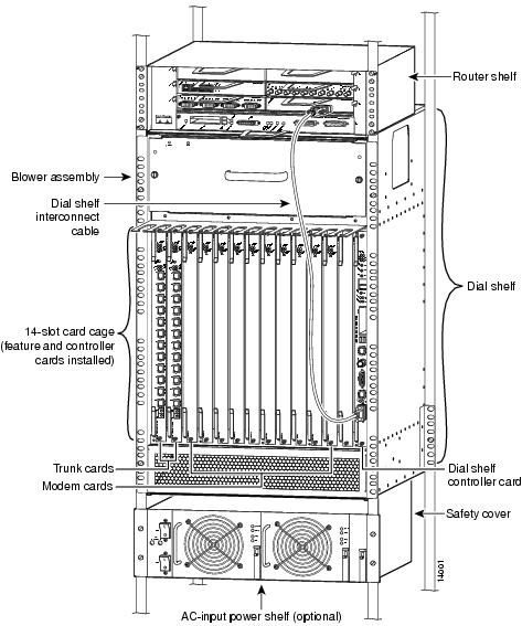
The Cisco AS5800 Universal Access Server is a high-density, ISDN and modem WAN aggregation system that provides both digital and analog call termination. It is intended to be used in service provider dial point-of-presence (POP), or centralized enterprise dial environments. The Cisco AS5800 Universal Access Server chassis components include a Cisco 5814 dial shelf and a Cisco 7206 router shelf. An optional AC power shelf is also available.
The dial shelf and router shelf are bundled, and can be ordered to support either AC or DC power. Included in the dial shelf is a blower assembly, filter module, and DC-input power entry modules (PEMs). Also included in the bundled system are ingress trunk cards, modem cards, dial shelf controller cards, Flash memory PCMCIA cards, cables, and Cisco IOS software. The dial shelf feature cards and host router shelf communicate via a dial shelf interconnect cable.
The dial shelf contains 14 slots (numbered 0 through 13 on the backplane) and can support up to 10 modem cards, 2 trunk cards, and 2 dial shelf controller cards. Slots 12 and 13 are dedicated slots for the dial shelf controller card(s). A single dial shelf controller card can be installed in either slot 12 or slot 13.
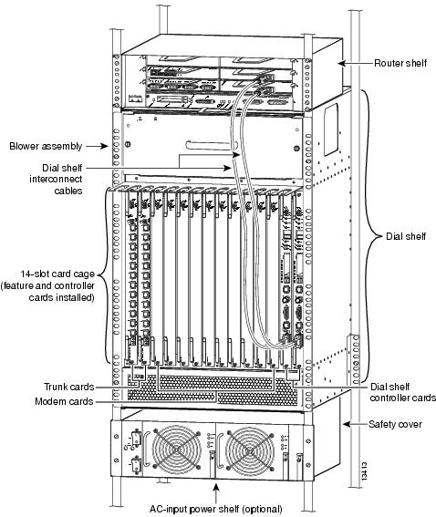
Redundancy is provided when 2 Dial Shelf Controllers (DSCs) are installed in the Dial Shelf. One DSC functions as a master. The master DCS provides all of the DCS functionality (master clock, environmental monitoring, etc.) for the Dial Shelf. The 2nd DSC functions as a slave that monitors the master DSC. The slave DSC takes over DSC functionality when it detects a serious failure in the master DSC.
Note
The router shelf supports the dial shelf and performs all routing and packet processing. The router shelf also houses the main system software images.
shows a front view of a fully configured Cisco AS5800 Universal Access Server. shows a rear view.
Figure 1 Cisco AS5800 Universal Access Server
with Single Dial Shelf Controller—Front View
Figure 2 Cisco AS5800 Universal Access Server
with Redundant Dial Shelf Controllers—Front View
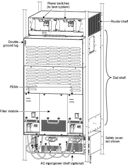
Figure 3 Cisco AS5800 Universal Access Server—Rear View
Dial Shelf Controller Card Overview
The dial shelf controller card is the main processor card for the dial shelf, and it performs the following functions:
•
•
A backplane interconnect concentrator on each dial shelf controller card connects to each feature card installed in the dial shelf.
•
•
•
•
You install the dial shelf controller card in the Cisco 5814 dial shelf in either of the 2 far-right slots (numbered on the backplane as 12 and 13). The card plugs directly into the backplane.
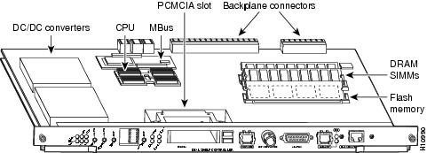
The dial shelf controller card consists of the following components:
•
•
•
•
•
•
•
lists the dial shelf controller card memory components and product numbers.
Table 1 Dial Shelf Controller Card Memory Components
DRAM
32 MB
2 16-MB SIMMS
MEM-DS58-16M
PCMCIA Flash
8 MB
16 MB
20 MBMEM-DS58-FLC8M=
MEM-DS58-FLC16M=
MEM-DS58-FLC20M=
shows the dial shelf controller card components.
Figure 4 Dial Shelf Controller Card Components
Note
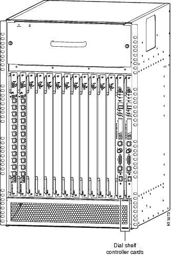
shows the front view of the Cisco 5814 dial shelf with 2 dial shelf controller cards installed.
Figure 5 Cisco 5814 Dial Shelf with Dial Shelf Controller Card Installed—Front View
LED Indicators and Alarm Buttons
The dial shelf controller card front panel contains several LEDs, pushbuttons, LCD displays, and connectors. Unlike the other feature cards installed in the Cisco 5814 dial shelf, the dial shelf controller card has 2 power LEDs, one for the card and the other for the system MBus power.
shows the dial shelf controller card front panel LEDs.
Figure 6 Dial Shelf Controller Card Front Panel LEDs
describes the dial shelf controller front panel LEDs. The LCD display information is included with LED information.
Table 2 Dial Shelf Controller LEDs, LCD Displays, and Descriptions
PWR (dial shelf controller power)
Green
Lights when power is ON.
MBUS (System MBus power)
Green
Lights when the dial shelf controller card is supplying +5 VDC to the system MBus.
MAJ (Major Alarm)
Yellow
Lights to indicate a major1 alarm condition.
MIN (Minor Alarm)
Yellow
Lights to indicate a minor2 alarm condition.
ACO (Alarm Cutoff)
Yellow
Lights to indicate the alarm cutoff button has been pressed.
HIST (history clear)
Yellow
Lights when software recognizes a major or minor alarm situation. LED powers off when the Clear Alarm button is pressed and no existing alarm condition remains.
CLK (Clock)
Green
Lights to indicate the dial shelf controller card active clock; active clock is independent from master dial shelf controller card designation.
MAST (master)
Green
Lights to indicate the system software recognizes the dial shelf controller card is in master mode.
Slot 0
Green
Lights when PCMCIA slot 0 is in use.
Slot 1
Green
Lights when PCMCIA slot 1 is in use.
DSI (dial shelf interconnect)
Green
Lights to indicate a working connection between the dial shelf and router shelf.
10BaseT (Ethernet link)
Green
Lights to indicate a working data transfer link connection between the access server and the system controller.
LCDs (upper and lower)
Alphanumeric 4 characters each
Displays ACTV to indicate active (master) card.
Displays BKUP to indicate backup (slave) card.
1 A major alarm condition includes router shelf failure, backplane interconnect failure, 2-fan failure, power supply failure, feature card failure, or conditional environmental thresholds.
2 A minor alarm condition includes modem SIMM failure, HDLC controller failure, or conditional environmental thresholds.
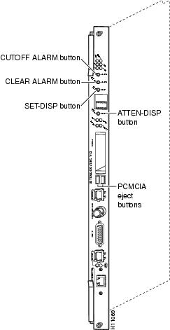
shows the dial shelf controller card front panel push-buttons, and describes push-button actions.
Figure 7 Dial Shelf Controller Card Front Panel Pushbuttons
Table 3
Dial Shelf Controller Card Pushbuttons
CautionPressing the ATTEN(tion) button on a given DSC has the effect of completely stopping all functionality on that DSC. There is no confirmation requested if the ATTEN push-button is pressed. The DSC is stopped without recourse.
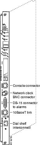
shows the dial shelf controller card front panel ports, and describes the port functions.
Figure 8 Dial Shelf Controller Card Ports
Warning
The ports labeled "Network clock," "10BaseT," "Dial Shelf Interconnect," "Console," and "Alarms" are safety extra-low voltage (SELV) circuits. SELV circuits should only be connected to other SELV circuits. Because the E1/T1 circuits are treated like telephone-network voltage, avoid connecting the SELV circuit to the telephone network voltage (TNV) circuits.
Note
Table 4
Dial Shelf Controller Card Front Panel Ports
lists dial shelf controller card environmental specifications.
Table 5
Dial Shelf Controller Card Environmental Specifications
Common Logic Interface
Each dial shelf controller card contains a block of logic referred to as the common logic and system clocks. This block generates the backplane Stratum-4 compliant 4-MHz and 8-KHz clocks used for interface timing and for the TDM bus data movement. The common logic can use a variety of sources to generate this system timing, including an E1 or T1 signal input from the BNC connector on the dial shelf controller card front panel.
Only one common logic is active a time, indicated by the CLK (clock) LED on the dial shelf controller card front panel. The active common logic is user-selectable and is independent from each dial shelf controller card. This assures that if you need to replace a dial shelf controller card, or if the slave dial shelf controller card becomes the master, clocking remains stable. The selected common logic should not be changed during normal operation unless a hardware failure in the dial shelf controller card is suspected or diagnosed.
Safety Guidelines
This section provides safety and ESD-prevention guidelines to help you avoid injury to yourself and avoid damage to the equipment. Cisco recommends the following safety guidelines when working with equipment that connects to electrical power or telephone wiring:
•
•
•
•
•
•
Preventing Electrostatic Discharge Damage
Electrostatic discharge (ESD) damages equipment and impairs electrical circuitry. ESD occurs when printed circuit boards are improperly handled and results in complete or intermittent failures.
The system feature cards and dial shelf controller cards consist of a printed circuit board that is fixed in a metal carrier. Electromagnetic interference (EMI) shielding, connectors, and a handle are integral components of the carrier. Handle the system feature cards and dial shelf controller cards by their carrier edges and handle only; never touch the printed circuit board components or connector pins.
Although the metal carrier helps to protect the printed circuit boards from ESD, wear a preventive antistatic strap whenever handling the dial shelf feature cards or dial shelf controller cards, or router shelf network processing engine, I/O controller, or port adapters. Ensure that the strap makes good skin contact and connect the strap's clip to an unpainted chassis surface to safely channel unwanted ESD voltages to ground.
If no wrist strap is available, ground yourself by touching the metal part of the chassis.
Cisco recommends the following guidelines to prevent ESD damage:
•
•
•
CautionPeriodically check the resistance value of the antistatic strap. The measurement should be within the range of 1 and 10 megohms.
Safety Warnings
Safety warnings appear throughout this publication in procedures that, if performed incorrectly, may harm you. A warning symbol precedes each warning statement.
Warning
This warning symbol means danger. You are in a situation that could cause bodily injury. Before you work on any equipment, be aware of the hazards involved with electrical circuitry and be familiar with standard practices for preventing accidents. To see translations of the warnings that appear in this publication, refer to the Regulatory Compliance and Safety Information document that accompanied this device.
Waarschuwing Dit waarschuwingssymbool betekent gevaar. U verkeert in een situatie die lichamelijk letsel kan veroorzaken. Voordat u aan enige apparatuur gaat werken, dient u zich bewust te zijn van de bij elektrische schakelingen betrokken risico's en dient u op de hoogte te zijn van standaard maatregelen om ongelukken te voorkomen. Voor vertalingen van de waarschuwingen die in deze publicatie verschijnen, kunt u het document Regulatory Compliance and Safety Information (Informatie over naleving van veiligheids- en andere voorschriften) raadplegen dat bij dit toestel is ingesloten.
Varoitus Tämä varoitusmerkki merkitsee vaaraa. Olet tilanteessa, joka voi johtaa ruumiinvammaan. Ennen kuin työskentelet minkään laitteiston parissa, ota selvää sähkökytkentöihin liittyvistä vaaroista ja tavanomaisista onnettomuuksien ehkäisykeinoista. Tässä julkaisussa esiintyvien varoitusten käännökset löydät laitteen mukana olevasta Regulatory Compliance and Safety Information -kirjasesta (määräysten noudattaminen ja tietoa turvallisuudesta).
Attention Ce symbole d'avertissement indique un danger. Vous vous trouvez dans une situation pouvant causer des blessures ou des dommages corporels. Avant de travailler sur un équipement, soyez conscient des dangers posés par les circuits électriques et familiarisez-vous avec les procédures couramment utilisées pour éviter les accidents. Pour prendre connaissance des traductions d'avertissements figurant dans cette publication, consultez le document Regulatory Compliance and Safety Information (Conformité aux règlements et consignes de sécurité) qui accompagne cet appareil.
Warnung Dieses Warnsymbol bedeutet Gefahr. Sie befinden sich in einer Situation, die zu einer Körperverletzung führen könnte. Bevor Sie mit der Arbeit an irgendeinem Gerät beginnen, seien Sie sich der mit elektrischen Stromkreisen verbundenen Gefahren und der Standardpraktiken zur Vermeidung von Unfällen bewußt. Übersetzungen der in dieser Veröffentlichung enthaltenen Warnhinweise finden Sie im Dokument Regulatory Compliance and Safety Information (Informationen zu behördlichen Vorschriften und Sicherheit), das zusammen mit diesem Gerät geliefert wurde.
Avvertenza Questo simbolo di avvertenza indica un pericolo. La situazione potrebbe causare infortuni alle persone. Prima di lavorare su qualsiasi apparecchiatura, occorre conoscere i pericoli relativi ai circuiti elettrici ed essere al corrente delle pratiche standard per la prevenzione di incidenti. La traduzione delle avvertenze riportate in questa pubblicazione si trova nel documento Regulatory Compliance and Safety Information (Conformità alle norme e informazioni sulla sicurezza) che accompagna questo dispositivo.
Advarsel Dette varselsymbolet betyr fare. Du befinner deg i en situasjon som kan føre til personskade. Før du utfører arbeid på utstyr, må du vare oppmerksom på de faremomentene som elektriske kretser innebærer, samt gjøre deg kjent med vanlig praksis når det gjelder å unngå ulykker. Hvis du vil se oversettelser av de advarslene som finnes i denne publikasjonen, kan du se i dokumentet Regulatory Compliance and Safety Information (Overholdelse av forskrifter og sikkerhetsinformasjon) som ble levert med denne enheten.
Aviso Este símbolo de aviso indica perigo. Encontra-se numa situação que lhe poderá causar danos físicos. Antes de começar a trabalhar com qualquer equipamento, familiarize-se com os perigos relacionados com circuitos eléctricos, e com quaisquer práticas comuns que possam prevenir possíveis acidentes. Para ver as traduções dos avisos que constam desta publicação, consulte o documento Regulatory Compliance and Safety Information (Informação de Segurança e Disposições Reguladoras) que acompanha este dispositivo.
¡Advertencia! Este símbolo de aviso significa peligro. Existe riesgo para su integridad física. Antes de manipular cualquier equipo, considerar los riesgos que entraña la corriente eléctrica y familiarizarse con los procedimientos estándar de prevención de accidentes. Para ver una traducción de las advertencias que aparecen en esta publicación, consultar el documento titulado Regulatory Compliance and Safety Information (Información sobre seguridad y conformidad con las disposiciones reglamentarias) que se acompaña con este dispositivo.
Varning! Denna varningssymbol signalerar fara. Du befinner dig i en situation som kan leda till personskada. Innan du utför arbete på någon utrustning måste du vara medveten om farorna med elkretsar och känna till vanligt förfarande för att förebygga skador. Se förklaringar av de varningar som förkommer i denna publikation i dokumentet Regulatory Compliance and Safety Information (Efterrättelse av föreskrifter och säkerhetsinformation), vilket medföljer denna anordning.
Online Insertion and Removal
The Cisco AS5800 Universal Access Server supports online insertion and removal (OIR), which allows you to remove and replace a dial shelf controller card or feature card while the system is operating, without affecting system operation.
Note
Each dial shelf controller card and feature card contains female connectors that connect to the system backplane. Each male backplane connector comprises a set of tiered pins, in 3 lengths. The backplane pins send specific signals to the system as they make contact with the card connectors. The system assesses the signals it receives and the order in which it receives them to determine whether to initialize a start-up or shutdown procedure.
Each dial shelf controller card and feature card is designed with two ejector levers to be used when you install or remove a card. The function of the ejector levers (see ) is to align and securely seat the card connectors in the backplane, and to facilitate the installation and removal process.
Do not force the dial shelf controller cards or feature cards into the slot, as this can damage the card connector pins if they are not aligned properly with the card connectors.
To avoid erroneous failure messages, you must allow at least 15 seconds for the system to reinitialize and note current interface configurations before you remove or insert another dial shelf controller card or feature card in the dial shelf.
Removing and Replacing a Dial Shelf Controller Card
This section lists tools and parts you need, and explains how to remove and replace a dial shelf controller card in the Cisco 5814 dial shelf chassis.
In most cases, the Cisco 5814 dial shelf chassis is shipped with the dial shelf controller card already installed. When installing your Cisco 5814 dial shelf chassis in a rack, Cisco recommends you first remove all feature cards and dial shelf controller cards to reduce the overall chassis weight.
If your Cisco 5814 dial shelf chassis, feature cards, and dial shelf controller cards have been shipped separately, proceed to the section "Replacing a Dial Shelf Controller Card."
CautionIf your system is equipped with dual DSCs, Cisco recommends that you perform DSC card replacements during low traffic periods.
Use the hw-module <shelf-id>/<slot-num> stop command to stop the backup DSC before you remove the backup (slave) DSC.
Tools and Parts Required
The following parts and tools are required to remove and replace the dial shelf controller card. If you need additional equipment, contact a service representative for ordering information.
•
•
•
•
•
•
Ensuring Easy System Access
If your Cisco AS5800 Universal Access Server is installed in a standard 19-inch, 4-post rack or standard telco rack, cables from other equipment in the rack might obstruct access to the rear of the system. Rack power strips or other permanent fixtures might also cause obstruction.
To ensure easy system access when the Cisco AS5800 Universal Access Server is installed in a rack:
•
•
Removing a Dial Shelf Controller Card
CautionDial shelf controller cards weigh 8.5 lb (3.8 kg) each. Use both hands when removing or replacing a dial shelf controller card (see ).
Warning


Use the hw-module <shelf-id>/<slot-num> stop command to stop the backup DSC before you remove the backup (slave) DSC.
To remove a dial shelf controller card, complete the following steps:

Note ![]() The power LED and MBus LED on the dial shelf controller card remains on until the card is disconnected from the backplane.
The power LED and MBus LED on the dial shelf controller card remains on until the card is disconnected from the backplane.
Step 1 ![]() Attach an ESD-preventive wrist strap between you and an unpainted chassis surface.
Attach an ESD-preventive wrist strap between you and an unpainted chassis surface.
Step 2 ![]() Disconnect all cables connected to the dial shelf controller card front panel.
Disconnect all cables connected to the dial shelf controller card front panel.
Step 3 ![]() Using a number 2 Phillips screwdriver, loosen the 2 panel fasteners on the top and bottom of the dial shelf controller card front panel. (See .)
Using a number 2 Phillips screwdriver, loosen the 2 panel fasteners on the top and bottom of the dial shelf controller card front panel. (See .)
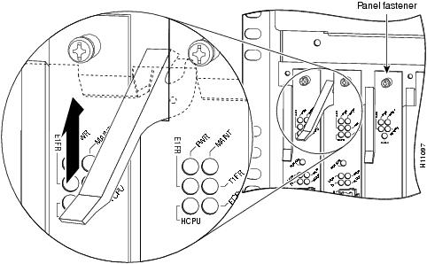
Step 4 ![]() Grasp the top and bottom ejector levers (refer to ) and pull them away from the front panel to disengage the dial shelf controller card from the backplane connectors.
Grasp the top and bottom ejector levers (refer to ) and pull them away from the front panel to disengage the dial shelf controller card from the backplane connectors.
Figure 9 Using the Ejector Levers
Step 5 ![]() Carefully slide the dial shelf controller card partially out of the slot, until you can grasp the card front panel with one hand. Place your other hand under the card to support it. (See .)
Carefully slide the dial shelf controller card partially out of the slot, until you can grasp the card front panel with one hand. Place your other hand under the card to support it. (See .)
Figure 10 Removing and Replacing a Dial Shelf Controller Card
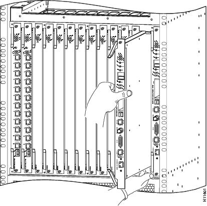
Note ![]() Use care when removing and installing the feature cards and dial shelf controller cards to avoid damage to the pin connectors. Only the feature cards and dial shelf controller cards should ever make contact with the backplane connectors.
Use care when removing and installing the feature cards and dial shelf controller cards to avoid damage to the pin connectors. Only the feature cards and dial shelf controller cards should ever make contact with the backplane connectors.
Step 6 ![]() Pull the dial shelf controller card straight out of the slot. Avoid touching the circuitry or any connector pins.
Pull the dial shelf controller card straight out of the slot. Avoid touching the circuitry or any connector pins.
Replacing a Dial Shelf Controller Card
Use the hw-module <shelf-id>/<slot-num> stop command to stop the backup DSC before you remove the backup (slave) DSC.
To replace a dial shelf controller card, complete the following steps:
Note ![]() The dial shelf controller card can be installed in either slot 12 or slot 13; however, if you install the replacement dial shelf controller card in the same slot, this will hasten the installation process.
The dial shelf controller card can be installed in either slot 12 or slot 13; however, if you install the replacement dial shelf controller card in the same slot, this will hasten the installation process.
Step 1 ![]() Ensure your ESD-preventive wrist strap is attached between you and an unpainted chassis surface.
Ensure your ESD-preventive wrist strap is attached between you and an unpainted chassis surface.
Step 2 ![]() Carefully align the dial shelf controller card carrier guides with the top and bottom grooves in the dial shelf slot. Avoid touching the circuitry or any connector pins.
Carefully align the dial shelf controller card carrier guides with the top and bottom grooves in the dial shelf slot. Avoid touching the circuitry or any connector pins.
Step 3 ![]() Slide the replacement dial shelf controller card into the dial shelf slot until the ejector levers make contact with the chassis frame. (Refer to to orient yourself with the dial shelf and dial shelf controller card.)
Slide the replacement dial shelf controller card into the dial shelf slot until the ejector levers make contact with the chassis frame. (Refer to to orient yourself with the dial shelf and dial shelf controller card.)
Step 4 ![]() Seat the dial shelf controller card in the backplane by pushing the card firmly until the ejector levers fold in toward the card front panel, and the front panel is flush with the chassis frame.
Seat the dial shelf controller card in the backplane by pushing the card firmly until the ejector levers fold in toward the card front panel, and the front panel is flush with the chassis frame.
Step 5 ![]() Using a number 2 Phillips screwdriver, tighten the panel fasteners. This secures the backplane connection and ensures proper EMI shielding.
Using a number 2 Phillips screwdriver, tighten the panel fasteners. This secures the backplane connection and ensures proper EMI shielding.
Step 6 ![]() Install a blank filler card (part number DS58-BLANK=) in all empty dial shelf card slots to keep the chassis dust free and to maintain proper air flow.
Install a blank filler card (part number DS58-BLANK=) in all empty dial shelf card slots to keep the chassis dust free and to maintain proper air flow.
This completes the steps for removing and replacing a dial shelf controller card. Proceed to the section "Connecting the Cables."
Note ![]() If you are installing the replacement dial shelf controller card into the same dial shelf slot as the card you just removed, the system recognizes the existing hardware configuration. There is no need to reconfigure the hardware. If you are installing the replacement dial shelf controller card in a different dial shelf slot, you must configure the hardware. Refer to the section "Configuring the Dial Shelf Controller Card."
If you are installing the replacement dial shelf controller card into the same dial shelf slot as the card you just removed, the system recognizes the existing hardware configuration. There is no need to reconfigure the hardware. If you are installing the replacement dial shelf controller card in a different dial shelf slot, you must configure the hardware. Refer to the section "Configuring the Dial Shelf Controller Card."
Connecting the Cables
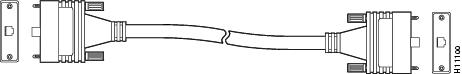
The dial shelf controller card includes a dial shelf interconnect cable to connect the card to the dial shelf interconnect port adapter in the Cisco 7206 router shelf. The connection between the dial shelf controller card and the dial shelf interconnect port adapter uses a single, full-duplex, interconnect cable, as shown in .
Figure 11 Dial Shelf Interconnect Cable
Attaching the Dial Shelf Interconnect Cable
To connect the dial shelf interconnect cable, complete the following steps:

Warning ![]()
Hazardous network voltages are present in WAN ports regardless of whether power to the router is OFF or ON. To avoid electric shock, use caution when working near WAN ports. When detaching cables, detach the end away from the router first.
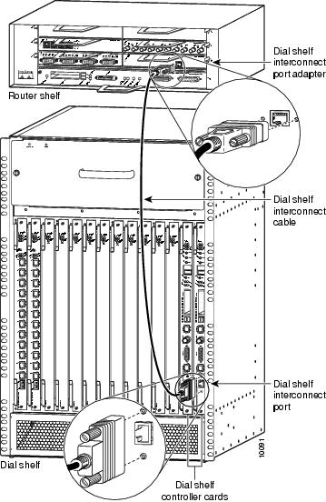
Step 1 ![]() Attach one end of your interconnect cable to the port labeled "Dial Shelf Interconnect" on the dial shelf controller card front panel. (See .)
Attach one end of your interconnect cable to the port labeled "Dial Shelf Interconnect" on the dial shelf controller card front panel. (See .)
Step 2 ![]() Tighten the jackscrews on either side of the connector.
Tighten the jackscrews on either side of the connector.
Step 3 ![]() Attach the other end of your cable to the RJ-45 port on the interconnect port adapter in the Cisco 7206 router shelf.
Attach the other end of your cable to the RJ-45 port on the interconnect port adapter in the Cisco 7206 router shelf.
Step 4 ![]() Tighten the jackscrews on either side of the connector.
Tighten the jackscrews on either side of the connector.
Figure 12 Connecting the Dial Shelf Interconnect Cable
Warning ![]()
The ports labeled "Network clock," "10BaseT," "Dial Shelf Interconnect," "Console," and "Alarms" are safety extra-low voltage (SELV) circuits. SELV circuits should only be connected to other SELV circuits. Because the E1/T1 circuits are treated like telephone-network voltage, avoid connecting the SELV circuit to the telephone network voltage (TNV) circuits.
For more information about the dial shelf interconnect cable and dial shelf interconnect port adapter, refer to the document Cisco AS5800 Universal Access Server Dial Shelf Interconnect Port Adapter Installation and Replacement (Part Number 78-4663-xx).
Verifying and Troubleshooting the Installation
Verify that your new dial shelf controller card is properly installed and operative by observing the card LEDs as follows:
•![]() Verify the power LED and MBus LED light after the dial shelf controller card has been fully installed in the dial shelf and the system is powered on.
Verify the power LED and MBus LED light after the dial shelf controller card has been fully installed in the dial shelf and the system is powered on.
•![]() If both the MBus and power LEDs are on, the card should boot normally. During the boot sequence, the 4 alarm LEDs should momentarily flash and then turn off. In addition, the two 4-character alphanumeric displays will show status messages.
If both the MBus and power LEDs are on, the card should boot normally. During the boot sequence, the 4 alarm LEDs should momentarily flash and then turn off. In addition, the two 4-character alphanumeric displays will show status messages.
After the boot sequence completes, the alphanumeric display should read:
MSTR
If the boot sequence does not complete, contact a service representative for assistance.
•![]() If either the power or MBus LED remains off, try removing and reinserting the card. If the problem persists, contact your service representative and replace the card.
If either the power or MBus LED remains off, try removing and reinserting the card. If the problem persists, contact your service representative and replace the card.
If the problem persists with a new card installed, remove the dial shelf controller card from the dial shelf slot and examine the backplane for bent connector pins.
To inspect the backplane pins, first power OFF the system to avoid hazards caused by high voltages present on the backplane connectors. Next, remove cards in neighboring slots to allow an unimpeded view of the backplane connectors. Then, using a flashlight, verify that the backplane connectors appear in good condition. If you discover bent pins, you need a new backplane. The backplane is not a field replaceable unit. Contact your service representative for instructions.
•![]() You can also use the show command to diagnose a problem with the dial shelf controller card. Enter the following command:
You can also use the show command to diagnose a problem with the dial shelf controller card. Enter the following command:
router> enable
enter password <password>
router# show diag <type {shelf | slot}>
Ctrl-Z
Configuring the Dial Shelf Controller Card
The Cisco 5814 dial shelf is designed to recognize dial shelf controller cards in specific slots within the dial shelf chassis. The backplane slots numbered 12 and 13 are the designated dial shelf controller card slots. This design supports redundancy features to further eliminate dropped calls.
Commands for Dual DSC Equipped Systems
The following new/modified commands have been added to support redundant DSC equipped systems.
Installing and Removing a Flash Memory Card
Both the router shelf and the dial shelf contain PCMCIA slots for inserting Flash memory cards. The router shelf PCMCIA slots are located on the I/O controller and are oriented horizontally; the dial shelf PCMCIA slots are located on the dial shelf controller card and are oriented vertically. Except for the orientation of the slots, the installation procedures are the same for both shelves.
This section describes inserting and removing a Flash memory card in the dial shelf. For procedures specific to the router shelf, refer to the Cisco 7206 Router Installation and Configuration Guide that shipped with your router shelf.
The dial shelf controller card has 2 PCMCIA slots for Flash memory cards. The slots are numbered left to right, slot 0 and slot 1, respectively. Complete the following steps to insert a Flash memory card in either dial shelf controller card PCMCIA slot:
Note ![]() To avoid potential problems when inserting spare Flash memory cards in your dial shelf controller cards, Cisco recommends that you reformat your Flash memory cards on a Cisco 7206 router shelf running Cisco IOS Release 11.3AA or later during your regularly scheduled service times. Refer to the Cisco 7206 Router Installation and Configuration Guide that shipped with your system for instructions on formatting a Flash memory card.
To avoid potential problems when inserting spare Flash memory cards in your dial shelf controller cards, Cisco recommends that you reformat your Flash memory cards on a Cisco 7206 router shelf running Cisco IOS Release 11.3AA or later during your regularly scheduled service times. Refer to the Cisco 7206 Router Installation and Configuration Guide that shipped with your system for instructions on formatting a Flash memory card.
Installing a Flash Memory Card
To install a Flash memory card, complete the following steps:
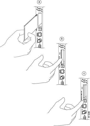
Step 1 ![]() Orient the Flash memory card so that the connector end faces the appropriate slot. (See .)
Orient the Flash memory card so that the connector end faces the appropriate slot. (See .)
Step 2 ![]() Carefully insert the card into the slot until it mates with the slot connector at the back of the slot. The eject button for the slot pops out toward you.
Carefully insert the card into the slot until it mates with the slot connector at the back of the slot. The eject button for the slot pops out toward you.
Note ![]() Flash memory cards do not insert completely flush with the dial shelf controller card front panel; a portion of the card remains outside of the slot. Do not attempt to force the card past this point.
Flash memory cards do not insert completely flush with the dial shelf controller card front panel; a portion of the card remains outside of the slot. Do not attempt to force the card past this point.
Removing a Flash Memory Card
To remove a Flash memory card from the PCMCIA slot, complete the following steps (see ):
Step 1 ![]() Press the ejector button on the slot.
Press the ejector button on the slot.
Step 2 ![]() Grasp the card and pull it from the slot.
Grasp the card and pull it from the slot.
Step 3 ![]() Place the card in an antistatic bag.
Place the card in an antistatic bag.
Figure 13 Inserting and Removing a PCMCIA Flash Card
This completes the dial shelf controller card and Flash memory installation procedures. If you have any questions or need assistance, proceed to the section "Cisco Connection Online."
FCC Compliance
Regulatory compliance and safety information for the Cisco AS5800 Universal Access Server is contained in the Regulatory Compliance and Safety Information document that shipped with your system.
Cisco Connection Online
Cisco Connection Online (CCO) is Cisco Systems' primary, real-time support channel. Maintenance customers and partners can self-register on CCO to obtain additional content and services.
Available 24 hours a day, seven days a week, CCO provides a wealth of standard and value-added services to Cisco's customers and business partners. CCO services include product information, software updates, release notes, technical tips, the Bug Navigator, configuration notes, brochures, descriptions of service offerings, and download access to public and authorized files.
CCO serves a wide variety of users through two interfaces that are updated and enhanced simultaneously—a character-based version and a multimedia version that resides on the World Wide Web (WWW). The character-based CCO supports Zmodem, Kermit, Xmodem, FTP, and Internet e-mail, and is excellent for quick access to information over lower bandwidths. The WWW version of CCO provides richly formatted documents with photographs, figures, graphics, and video, as well as hyperlinks to related information.
You can access CCO in the following ways:
•![]() WWW: http://www.cisco.com
WWW: http://www.cisco.com
•![]() WWW: http://www-europe.cisco.com
WWW: http://www-europe.cisco.com
•![]() WWW: http://www-china.cisco.com
WWW: http://www-china.cisco.com
•![]() Telnet: cco.cisco.com
Telnet: cco.cisco.com
•![]() Modem: From North America, 408 526-8070; from Europe, 33 1 64 46 40 82. Use the following terminal settings: VT100 emulation; databits: 8; parity: none; stop bits: 1; and connection rates up to 28.8 kbps.
Modem: From North America, 408 526-8070; from Europe, 33 1 64 46 40 82. Use the following terminal settings: VT100 emulation; databits: 8; parity: none; stop bits: 1; and connection rates up to 28.8 kbps.
For a copy of CCO's Frequently Asked Questions (FAQ), contact cco-help@cisco.com. For additional information, contact cco-team@cisco.com.
Note ![]() If you are a network administrator and need personal technical assistance with a Cisco product that is under warranty or covered by a maintenance contract, contact Cisco's Technical Assistance Center (TAC) at 800 553-2447, 408 526-7209, or tac@cisco.com. To obtain general information about Cisco Systems, Cisco products, or upgrades, contact 800 553-6387, 408 526-7208, or cs-rep@cisco.com.
If you are a network administrator and need personal technical assistance with a Cisco product that is under warranty or covered by a maintenance contract, contact Cisco's Technical Assistance Center (TAC) at 800 553-2447, 408 526-7209, or tac@cisco.com. To obtain general information about Cisco Systems, Cisco products, or upgrades, contact 800 553-6387, 408 526-7208, or cs-rep@cisco.com.
78-4653-02