Feedback Feedback
|
Table Of Contents
Managing and Troubleshooting NextPort Services on the UPC
Port Configuration Mode Commands
SPE Configuration Mode Commands
Disable a Port from Dial-Up Services
Upgrading SPE Firmware and Cisco IOS Images
Displaying SPE Firmware Versions
Upgrading SPE Firmware from the Cisco CCO TFTP Server
Download SPE Firmware from the Cisco CCO TFTP Server to a Local TFTP Server
Copy the SPE Firmware File from Local TFTP Server to the SPEs
Upgrading SPE Firmware from Diskettes
Copy the SPE Firmware to Your PC Hard Disk
Copy the SPE Firmware from Your PC to the SPEs
Using the SPE Firmware Bundled with Cisco IOS Software
Managing and Troubleshooting NextPort Services on the UPC
The Cisco AS5800 universal access servers support universal port carrier cards, and DMM modem cards. For details on these modem carrier cards, refer to the Cisco AS5800 Universal Access Server Hardware Installation Guide and Cisco AS5800 Universal Access Server Dial Shelf Card Guide. The universal port card (UPC) supports NextPort hardware and software interfaces. A port is defined as the binding of a TDM channel, service, and data queue to support a bidirectional service on the UPC. A universal port is a port on a UPC that can be switched freely between two or more services without changing the TDM channel.
You can manage port connections at the UPC, service proccessing element (SPE—the processor on the slot card that executes protocols to process in-band data) or port level using monitoring, polling, and troubleshooting commands. NextPort management functions are very similar to MICA modem (DMM) management functions. This document discusses procedures and commands similar in both types of services and procedures, and some unique to the NextPort architecture.
NextPort introduces shelf, slot, and SPE software hierarchies. On the Cisco AS5800, the hierarchy is shelf/slot/spe. The user can perform the following functions on an SPE:
•
General configuration such as busyout, shutdown, or clear
•
•
•
•
This document includes the following sections:
•
SPE Performance Statistics
Configuration
By default, event logging is enabled, and SPEs are polled every 12 sec. The log contains raw data in binary form, which must be viewed using the show commands listed in the "Viewing Statistics" section.You may configure some aspects of how the record is kept using the following global configuration mode commands [at the AS5800(config)# prompt]:
•
•
•
•
The following Enable Mode (also called Privileged EXEC Mode) commands allow you to clear some or all of the log events relating to the SPEs (at the AS5800# prompt):
•
•
•
Viewing Statistics
You can view SPE statistics using the Cisco IOS software with the Cisco AS5800. To view performance statistics for the UPCs, enter one or more of the following commands in Enable Mode (also called Privileged EXEC Mode), at the AS5800# prompt:
•
•
•
•
•
•
•
•
•
•
•
•
•
•
•
•
•
•
•
•
•
•
Managing Ports
This section describes how to manage NextPort ports by clearing ports, entering port configuration mode, removing ports from service, and disabling ports from dial-up service. For details on disabling a port from dial-up services, see the section, "Troubleshooting" on page 6.
Clear Ports
Ports may need to be cleared if polling attempts have failed and the port is removed from operation.This is done using the clear port command.
Use the show spe shelf/slot/spe command to view the active ports on an SPE. To clear ports on an SPE, enter the following command in Enable Mode (also called Privileged EXEC Mode). The user can clear all ports on the NAS, all ports on a slot, or a port. This replaces the clear modem command.
•
AS5800# clear port 1/4/1AS5800#•
AS5800# clear port 1/4AS5800#Port Configuration Mode
Port configuration mode allows the user to enter a mode similar to the line configuration mode. This mode allows individual ports or ranges of ports to be shut down or put in busyout mode. Port configuration mode commands replace the modem range, modem busyout, and modem shutdown commands used with MICA modems.
•
AS5800# configure terminalEnter configuration commands, one per line. End with CNTL/Z.AS5800(config)# port 1/3/1AS5800(config-port)#•
AS5800# configure terminalEnter configuration commands, one per line. End with CNTL/Z.AS5800(config)# port 1/3/1 1/3/18AS5800(config-port)#Port Configuration Mode Commands
The following commands are available in port configuration mode:
•
•
Managing SPEs
This section describes how to manage SPEs by setting the SPE country code, clearing the SPEs, entering SPE configuration mode, upgrading the SPE firmware, and performing busyout on SPEs.
SPE Country
Enter this global configuration mode command to specify the country to set the UPC parameters (including country code and encoding) for UPCs. The default is usa if the access server is configured with T1 interfaces and e1-default if the access server has E1 interfaces. Use the no form of this command to set the country code to the default of domestic.
Note
A list of all supported countries is displayed in the help file. This replaces the modem country command.
•
AS5800(config)# spe country e1-defaultSPE Configuration Mode
SPE configuration mode allows the user to enter the SPE configuration mode, which is similar to the line configuration mode. The user can configure an SPE by specifying a slot and an SPE associated with the slot or, the user can choose to configure a range of SPEs by specifying the first & last SPE in the range.
•
AS5800# config tEnter configuration commands, one per line. End with CNTL/Z.AS5800(config)# spe 1/1 1/18AS5800(config-SPE)#SPE Configuration Mode Commands
The following commands are available in SPE configuration mode:
•
•
•
•
Troubleshooting
This section describes how to perform diagnostic testing on installed ports or SPEs, test two ports back-to-back, disable ports from service, and recover a port that is frozen.
Configure SPE Self Tests
To perform self-diagnostic testing on all the installed ports during the system's initial startup or rebooting process, or during service, enter the following command in global configuration mode [the prompt is displayed as AS5800(config)#]:
•
The results of the SPE self test are displayed in the Status column of the output from the show spe modem and show spe modem active commands. Ports that pass the diagnostic test are marked as Idle, Busy, Downloading, and Reset, and are put into service. Ports that fail the diagnostic test are marked as Bad, and are not put into service or tested again until they are no longer marked as Bad. If all the ports of an SPE are bad, the corresponding SPE is also marked bad. These ports cannot be used for call connections. Depending on how many ports are present and not marked Bad, this diagnostic test may take from 5 to 15 minutes to complete. You may perform additional testing on an inoperative port by executing the test modem back-to-back command. The no port modem autotest command disables testing.
You may additionally configure the following options:
•
•
Test Two Ports Back-to-Back
When a port has tested as being Bad, you may perform additional testing by conducting a series of internal back-to-back connections and data transfers between two ports. All port test connections occur inside the access server. For example, if mobile users cannot dial into port 1/2/5 (which is the sixth port on the UPC in the second chassis slot oof shelf 1), attempt a back-to-back test with port 1/2/5 and a known-functioning port such as port 1/2/6.
Enter the following command in enable mode (the prompt is displayed as 5800#) to perform internal back-to-back port tests between two ports:
•
You might need to enable this command on several different combinations of ports to determine which one is not functioning properly. A pair of operable ports successfully connect and complete transmitting data in both directions. An operable port and an inoperable port do not successfully connect with each other.
A sample back-to-back test might look like the following:
AS5800# test modem back-to-back 1/6/7 1/6/100AS5800#.Feb 10 16:56:19.536: %PM_MODEM_MAINT-5-B2BCONNECT: Modems (1/6/07) and (1/6/100) connected in back-to-back test: CONNECT33600/V34/LAP.Feb 10 16:56:25.708: %PM_MODEM_MAINT-5-B2BMODEMS: Modems (1/6/100) and (1/6/07) completed back-to-back test: success/packets = 200/200If you attempt a back to back test on a port that is in use, the output will resemble the following example:
AS5800# test modem back-to-back 1/6/7 1/6/100Repetitions (of 10-byte packets) [1]: 100Modem 1/6/07 is currently busy, Back-to-back Test will be delayed.A port that has been confirmed to have problems can often be fixed using the clear spe command. For more information, see the "Clear an SPE" section.
Disable a Port from Dial-Up Services
To disable ports from dialing or answering calls, enter one of the following commands in port configuration mode [the prompt is displayed as AS5800(config-port)#]:
•
•
The busyout command is not executed until the active port is idle. No active connections are interrupted when you use this command. In contrast, the shutdown command immediately terminates all active connections on the specified port. The resulting port status for both these commands is the same. Enable the no form of these commands to restore a port for dial-up services.
You can still configure the following commands on a disabled port:
•
•
You may also disable ports on specified SPEs in SPE configuration mode [the prompt is displayed as AS5800(config-SPE)#]. Some problems with ports require a reload of SPE firmware, and all ports on an SPE will need to be out of service to reload the firmware.
SPE Recovery
Configure automatic recovery (removal from service and reloading of SPE firmware) of ports on an SPE at any available time from global configuration mode as shown [the prompt is displayed as 5800(config)#]:
•
When an SPE port fails to connect for a certain number of consecutive times, it indicates that a problem exists in a specific part or the whole of SPE/firmware. Such SPEs have to be recovered by downloading firmware. Any port failing to connect num-failures times will be moved to a state based on port-action, where you can choose to disable (mark the port as Bad) or recover the port when the SPE is in IDLE and has no active calls. The default for num-failures is 30.
You may also schedule recovery using the spe download maintenance configuration command.
SPE Download Maintenance
Configure a scheduled recovery of SPEs from global configuration mode as shown [the prompt is displayed as 5800(config)#]:
•
Download maintenance starts at time, steps through all the SPEs that need recovery and SPEs that need a firmware upgrade and starts maintenance on max-spes at a time. It waits for the window delay time for all the ports on the SPE to become inactive before moving the SPE to the Idle state. It will download firmware immediately after the SPE moves to idle. If the ports are still in use by the end of (window), depending on the expired-window setting, the port marked for recovery can be set to be moved to the disabled state by choosing the disable option, connections on the SPE ports will be shutdown and the firmware will downloaded by choosing the drop-call option, or the firmware download is rescheduled to the next download maintenance time by choosing the reschedule option. This process continues until the number of SPEs under maintenance are below max-spes, or until stop-time (if set), or until all SPEs marked for recovery or upgrade have had their firmware reloaded.
Clear an SPE
The clear spe Enable Mode (also called Privileged EXEC Mode) command allows the user to manually recover a port that is frozen in a suspended state. This command causes the firmware configured for that SPE to be downloaded to the specified SPE or the range of SPEs and Power on Self Test (POST) to be executed. This command can be executed regardless of the state of the SPEs. All active ports running on the SPE are prematurely terminated and messages are logged into the appropriate log. This replaces the clear modem command.
The following example shows a coldstart on SPE 1 on slot 1.
AS5800# clear spe 1/1/1AS5800# Are you sure you want to clear SPE 1/1/1(Y/N)? YUpgrading SPE Firmware and Cisco IOS Images
Cisco IOS Release 12.1(2)XD or later is required for using UPCs on the Cisco AS5800. Matching Cisco IOS images are needed for both the router shelf and the dial shelf. The required images should have been shipped with your UPC, and the Cisco IOS software may be upgraded using the same instructions as are used for upgrading unbundled firmware files.
At startup, UPCs copy a Cisco IOS software-compatible version of SPE firmware to the installed SPEs. By default, the SPE firmware version bundled with the current version of the Cisco IOS is loaded, but the SPEs may be configured to use unbundled SPE firmware files.
Note
You can acquire new SPE firmware in several ways:
•
•
•
After you have the new firmware, you can configure different firmware versions onto individual SPEs or ranges of SPEs on a UPC. You can also configure different upgrade methods.
This section describes how to upgrade SPE firmware handling your access server ports by:
1.
2.
3.
4.
How to Obtain SPE Firmware
You can obtain SPE firmware in one of two ways:
•
•
Important Upgrade Commands
There are several commands you use to upgrade SPE firmware. For examples on using the commands, see "Upgrading SPE Firmware from the Cisco CCO TFTP Server," "Upgrading SPE Firmware from Diskettes," and "Using the SPE Firmware Bundled with Cisco IOS Software" on page 24.
•
•
•
Note
Choosing an Update Strategy
Because of multiple versions of SPE firmware and the way Cisco IOS software processes these versions, Cisco suggests that you choose one of the following two strategies:
•
•
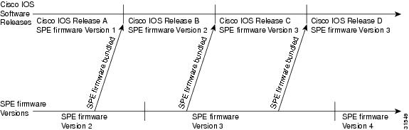
To help with the decision, Figure 3 shows a hypothetical release process. Using the SPE firmware bundled with Cisco IOS software is the easier strategy and enables you to take advantage of new SPE firmware whenever you upgrade your Cisco IOS software. You can control the SPE firmware by using the copy command as discussed later.
Figure 3 Release Timeline for Cisco IOS Software and SPE Firmware
SPE Firmware Scenarios
Table 5 provides scenarios that can occur when you upgrade Cisco IOS software or SPE firmware.
Table 5 Cisco IOS and SPE firmware upgrade scenarios
Step 1
You receive a new access server from the Cisco factory.
•
Step 2
You update Cisco IOS software, and you decide to use the version of SPE firmware selected by Cisco IOS software.
•
•
Step 3
You update Cisco IOS software, and you decide not to use the SPE firmware selected by Cisco IOS software.
•
•
Step 4
The SPEs are running a version of SPE firmware from system Flash memory that is different than the version bundled with Cisco IOS software. You decide to revert to the bundled version.
•
Step 5
Cisco releases new SPE firmware, which is a later version than the version currently running on the SPEs. You decide to use Cisco's newest SPE firmware.4
•
1 To find out the version of SPE firmware in your system, use the show spe version command. This command displays the versions running on the SPEs.
2 In part, Cisco IOS software bases this decision on the last copy command issued.
3 The copy ios-bundled command is not necessary with UPCs. By default, the version of SPE firmware bundled with the Cisco IOS software release transfers to all SPEs not specifically configured for a different SPE firmware file.
4 Cisco might ship this SPE firmware on a diskette packed with the spare carrier card.
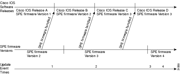
Figure 4 shows a location on the release timeline where updates might take place, and Table 6 explains the resulting versions of Cisco IOS software and SPE firmware.
Figure 4 Release Timeline for Cisco IOS Software and SPE Firmware
Table 6 Cisco IOS and SPE firmware results
Cisco IOS Software
and SPE FirmwareStep 1
You upgrade Cisco IOS software to Release B.
•
•
•
•
SPE firmware Version 2•
SPE firmware Version 2•
SPE firmware Version 1Step 2
You upgrade Cisco IOS software to Release C. (Cisco IOS software uses mapping from last copy command at Time 1).1
Cisco IOS Release C
SPE firmware Version 1Step 3
New SPE firmware Version 4 is released, you copy the file to system Flash memory, enter copy flash modem, and specify SPE firmware Version 4.
Cisco IOS Release C
SPE firmware Version 4Step 4
You upgrade Cisco IOS software to Release D.
Cisco IOS Release D
SPE firmware Version 4
1 This example assumes the last copy command was copy flash modem, and SPE firmware Version 1 was specified.
Displaying SPE Firmware Versions
Use the show spe version command to list the versions of SPE firmware running on the SPEs, residing in system Flash memory, and bundled with Cisco IOS software. This will help you decide if you need to change the version running on the modems.
The following example shows an example of the show SPE command for a system with one 324 universal port card.
AS5800# show spe versionAS5800#show spe versionIOS-Bundled Default Firmware-Filename Version Firmware-Type===================================== ======= =============system:/ucode/np_spe_firmware1 0.6.6.9 SPE firmwareOn-Flash Firmware-Filename Version Firmware-Type========================== ======= =============slot0:np.spe_36 0.6.6.5 SPE firmwareSPE-# SPE-Type SPE-Port-Range Version UPG Firmware-Filename1/04/00 CSMV6 0000-0005 0.6.6.9 N/A ios-bundled default1/04/01 CSMV6 0006-0011 0.6.6.9 N/A ios-bundled default1/04/02 CSMV6 0012-0017 0.6.6.9 N/A ios-bundled default1/04/03 CSMV6 0018-0023 0.6.6.9 N/A ios-bundled default1/04/04 CSMV6 0024-0029 0.6.6.9 N/A ios-bundled default1/04/05 CSMV6 0030-0035 0.6.6.9 N/A ios-bundled default1/04/06 CSMV6 0036-0041 0.6.6.9 N/A ios-bundled default1/04/07 CSMV6 0042-0047 0.6.6.9 N/A ios-bundled default1/04/08 CSMV6 0048-0053 0.6.6.9 N/A ios-bundled default1/04/09 CSMV6 0054-0059 0.6.6.9 N/A ios-bundled default1/04/10 CSMV6 0060-0065 0.6.6.9 N/A ios-bundled default...1/04/30 CSMV6 0180-0185 0.6.6.9 N/A ios-bundled default1/04/31 CSMV6 0186-0191 0.6.6.9 N/A ios-bundled default1/04/32 CSMV6 0192-0197 0.6.6.9 N/A ios-bundled default1/04/33 CSMV6 0198-0203 0.6.6.9 N/A ios-bundled default1/04/34 CSMV6 0204-0209 0.6.6.9 N/A ios-bundled default1/04/35 CSMV6 0210-0215 0.6.6.9 N/A ios-bundled default1/04/36 CSMV6 0216-0221 0.6.6.9 N/A ios-bundled default1/04/37 CSMV6 0222-0227 0.6.6.9 N/A ios-bundled default1/04/38 CSMV6 0228-0233 0.6.6.9 N/A ios-bundled default1/04/39 CSMV6 0234-0239 0.6.6.9 N/A ios-bundled default1/04/40 CSMV6 0240-0245 0.6.6.9 N/A ios-bundled default1/04/41 CSMV6 0246-0251 0.6.6.9 N/A ios-bundled default1/04/42 CSMV6 0252-0257 0.6.6.9 N/A ios-bundled default1/04/43 CSMV6 0258-0263 0.6.6.9 N/A ios-bundled default1/04/44 CSMV6 0264-0269 0.6.6.9 N/A ios-bundled default1/04/45 CSMV6 0270-0275 0.6.6.9 N/A ios-bundled default1/04/46 CSMV6 0276-0281 0.6.6.9 N/A ios-bundled default1/04/47 CSMV6 0282-0287 0.6.6.9 N/A ios-bundled default1/04/48 CSMV6 0288-0293 0.6.6.9 N/A ios-bundled default1/04/49 CSMV6 0294-0299 0.6.6.9 N/A ios-bundled default1/04/50 CSMV6 0300-0305 0.6.6.9 N/A ios-bundled default1/04/51 CSMV6 0306-0311 0.6.6.9 N/A ios-bundled default1/04/52 CSMV6 0312-0317 0.6.6.9 N/A ios-bundled default1/04/53 CSMV6 0318-0323 0.6.6.9 N/A ios-bundled defaultUpgrading SPE Firmware from the Cisco CCO TFTP Server
Upgrading SPE firmware from the Cisco CCO TFTP server is a two-step process:
•
•
Note
Download SPE Firmware from the Cisco CCO TFTP Server to a Local TFTP Server
Note
You can download software from the Cisco Systems CCO TFTP server using an Internet browser or using an FTP application. Both procedures are described.
Note
Using an Internet Browser
Step 1
Step 2
http://www.cisco.com/kobayashi/sw-center/
Step 3
Step 4
Step 5
Step 6
Step 7
Step 8
Using an FTP Application
Note
Step 1
terminal> ftp cco.cisco.comConnected to cio-sys.cisco.com.220-220- Cisco Connection Online | | Cisco Systems, Inc.220- Email: cco-team@cisco.com ||| ||| 170 West Tasman Drive220- Phone: +1.800.553.2447 .:|||||:..:|||||:. San Jose, CA 95134220-220- NOTE: As of February 1,1997 ftp.cisco.com will now point to this220- service. Please be advised. To use the former ftp.cisco.com after220- February 1, connect to ftpeng.cisco.com220-220- You may login with:220- + Your CCO username and password, or220- + A special access code followed by your e-mail address, or220- + "anonymous" followed by your e-mail address for guest access.220-220 cio-sys FTP server (CIOESD #103 Sun Dec 15 14:43:43 PST 1996) ready.Step 2
Name (cco.cisco.com:harry): harry331 Password required for harry.Password: letmein230-#############################################################230-# Welcome to the Cisco Systems CCO FTP server.230-# This server has a number of restrictions. If you are not familiar230-# with these, please first get and read the /README or /README.TXT file.230-# http://www.cisco.com/acs/info/cioesd.html for more info.230-#############################################################230-230- ***** NOTE: As of February 1, 1997, "cco.cisco.com", *****230- ***** "www.cisco.com" and "ftp.cisco.com" are now all *****230- ***** logical names for the same machine. *****230- ***** *****230- ***** The old "ftp.cisco.com" is an entirely *****230- ***** different machine, which is now known as *****230- ***** "ftpeng.cisco.com" or "ftp-eng.cisco.com". *****230- ***** *****230- ***** In general, "ftpeng.cisco.com" is used only for ****230- ***** distribution of Cisco Engineering-controlled *****230- ***** projects, such as beta programs, early field *****230- ***** trials, developing standards documents, etc. *****230- ***** *****230- ***** Be sure to confirm you have connected to *****230- ***** the machine you need to interact with. *****230-230- If you have any odd problems, try logging in with a minus sign (-) as230- the first character of your password. This will turn off a feature230- that may be confusing your ftp client program.230- Please send any questions, comments, or problem reports about this230- server to cco-team@cisco.com.230-230- NOTE:230- o To download files from CCO, you must be running a *passive-mode*230- capable FTP client.230- o To drop files on this system, you must cd to the /drop directory.230- o Mirrors of this server can be found at230-230- + ftp://www-europe.cisco.com European (Amsterdam)230- + ftp://www-fr.cisco.com France (Paris)230- + ftp://www-au.cisco.com Australia (Sydney)230- + ftp://www-jp.cisco.com Japan (Tokyo)230- + ftp://www-kr.cisco.com Korea (Seoul)230-230-Please read the file README230- it was last modified on Sat Feb 1 12:49:31 1997 - 163 days ago230 User harry logged in. Access restrictions apply.Remote system type is UNIX.Using binary mode to transfer files.Step 3
ftp> cd /cisco/access/5800250-Please read the file README250- it was last modified on Tue May 27 10:07:38 1997 - 48 days ago250-Please read the file README.txt250- it was last modified on Tue May 27 10:07:38 1997 - 48 days ago250 CWD command successful.Step 4
ftp> ls227 Entering Passive Mode (192,31,7,130,218,128)150 Opening ASCII mode data connection for /bin/ls.total 2688drwxr-s--T 2 ftpadmin ftpcio 512 Jun 30 18:11 .drwxr-sr-t 19 ftpadmin ftpcio 512 Jun 23 10:26 ..lrwxrwxrwx 1 root 3 10 Aug 6 1996 README ->README.txt-rw-rw-r-- 1 root ftpcio 2304 May 27 10:07 README.txt-r--r--r-- 1 ftpadmin ftpint 377112 Jul 10 18:08 SPE-firmware.x.x.x.bin-r--r--r-- 1 ftpadmin ftpint 635 Jul 10 18:08 SPE-firmware.3.1.30.readme226 Transfer complete.Step 5
ftp> binary200 Type set to I.Step 6
Step 7
ftp> quitGoodbye.Step 8
server% ls -altotal 596-r--r--r-- 1 280208 Jul 10 18:08 SPE-firmware.x.x.x.binserver% pwd/auto/tftpbootStep 9
Copy the SPE Firmware File from Local TFTP Server to the SPEs
The procedure for copying the SPE firmware file from your local TFTP server to the UPCs is a two-step process. First, transfer the SPE firmware to the access server's Flash memory. Then, configure the SPEs to use the upgrade firmware. The upgrade will occur automatically, either as you leave configuration mode, or as specified in the configuration.
These two steps are performed only once. After you copy the SPE firmware file into Flash memory for the first time, you should not have to perform these steps again. Because the SPE firmware is configurable for individual SPEs or ranges of SPEs, the Cisco IOS software automatically copies the SPE firmware to each SPE whenever-- the access server restarts.
The following procedure assumes your terminal is connected directly to the console port on the AS5800 router shelf. Use these steps to download the NextPort SPE firmware to flash:
Step 1
AS5800# show flashSystem flash directory:File Length Name/status1 4530624 c5800-js-mx[498776 bytes used, 16278440 available, 16777216 total]16384K bytes of processor board System flash (Read/Write)Step 2
AS5800# copy tftp flashSystem flash directory:File Length Name/status1 4530624 images/c5800-js-mx[498776 bytes used, 16278440 available, 16777216 total]Address or name of remote host [255.255.255.255]? juraiSource file name? SPE-firmware.x.x.x.x.binDestination file name [SPE-firmware.x.x.x.x.bin]?Accessing file 'SPE-firmware.x.x.x.x.bin' on 255.255.255.255...Loading SPE-firmware.x.x.x.x.bin from 2.2.0.1 (via Ethernet0): ! [OK]Erase flash device before writing? [confirm] noCopy 'SPE-firmware.x.x.x.x.bin' from serveras 'SPE-firmware.x.x.x.x.bin' into Flash WITHOUT erase? [yes/no] yesLoading images/SPE-firmware.x.x.x.x.bin from 2.2.0.1 (via Ethernet0):!!!!!!!!!!!!!!!!!!!!!!!!!!!!!!!!!!!!!!!!!!!!!!!!![OK - 249108/16278440 bytes]Verifying checksum... OK (0xE009)Flash device copy took 00:00:02 [hh:mm:ss]Step 3
AS5800# show flashSystem flash directory:File Length Name/status1 4530624 c5800-js-mz2 210104 SPE-firmware.x.x.x.x.bin[747948 bytes used, 16029268 available, 16777216 total]16384K bytes of processor board System flash (Read/Write)Step 4
Step 5
AS5800# copy tftp flashSystem flash directory:File Length Name/status1 4530624 images/c5800-js-mx[498776 bytes used, 16278440 available, 16777216 total]Address or name of remote host [255.255.255.255]? juraiSource file name? SPE-firmware.x.x.x.x.binDestination file name [SPE-firmware.x.x.x.x.bin]?Accessing file 'SPE-firmware.x.x.x.x.bin' on 255.255.255.255...Loading SPE-firmware.x.x.x.x.bin from 2.2.0.1 (via Ethernet0): ! [OK]Erase flash device before writing? [confirm] noCopy 'SPE-firmware.x.x.x.x.bin' from serveras 'SPE-firmware.x.x.x.x.bin' into Flash WITHOUT erase? [yes/no] yesLoading images/SPE-firmware.x.x.x.x.bin from 2.2.0.1 (via Ethernet0):!!!!!!!!!!!!!!!!!!!!!!!!!!!!!!!!!!!!!!!!!!!!!!!!![OK - 249108/16278440 bytes]Verifying checksum... OK (0xE009)Flash device copy took 00:00:02 [hh:mm:ss]To configure the SPEs to use an upgraded firmware file:
Step 1
AS5800# enableStep 2
Password: passwordAS5800#You are in privileged EXEC mode when the prompt changes to AS5800#
Step 3
AS5800# configure terminalEnter configuration commands, one per line. End with CNTL/Z.AS5800(config)#You are in global configuration mode when the prompt changes to AS5800(config)#.
Step 4
AS5800(config)# spe shelf/slot/speorAS5800(config)# spe shelf/slot/spe shelf/slot/speYou are in SPE configuration mode when the prompt changes to AS5800(config-SPE)#.
Step 5
AS5800(config-SPE)# firmware location filenameStep 6
AS5800(config-SPE)# firmware upgrade busyout | download-maintenance | rebootStep 7
AS5800(config-SPE)# exitAS5800(config)#Step 8
AS5800(config)# Ctrl-ZAS5800#Step 9
AS5800# copy running-config startup-configUpgrading SPE Firmware from Diskettes
This section describes how to copy SPE firmware from diskettes to your hard disk in a PC environment, and then upload the SPE firmware to the SPEs. The steps are similar if you are using a Macintosh or UNIX workstation.
Note
Copy the SPE Firmware to Your PC Hard Disk
This section describes how to copy the SPE firmware file to your hard disk in a PC environment. The steps are similar if you are using a Macintosh or a UNIX workstation.
Step 1
Step 2
Step 3
Copy the SPE Firmware from Your PC to the SPEs
If you are using a PC running Microsoft Windows, upgrading SPE firmware from a hard drive onto a Cisco AS5800 involves installing a TFTP application on your PC, connecting your PC and the access server, establishing a HyperTerminal session on your PC, pinging the PC and access server to make sure they are talking to each other, and finally, copying the SPE firmware from the PC to the access server. See the following sections for details.
Note
Set Up a TFTP Application on the PC
Step 1
Note
Step 2
Step 3
•
•
•
Caution
Connect your PC and the Access Server
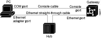
Step 1
Figure 5 Connecting a PC and an Access Server
Note
Step 2
Step 3
Establish a HyperTerminal Session
Use the steps in this section to establish a HyperTerminal session from your local PC to the Cisco AS5800. You will use the HyperTerminal session to talk to the access server.
Step 1
Step 2
Step 3
Step 4
Step 5
Step 6
•
•
•
•
•
Step 7
Step 8
Note
Ping the PC and Access Server
Ping the access server and the PC to make sure they are talking to each other and there are no configuration problems on your access server.
Step 1
a.
b.
c.
d.
Note
Step 2
AS5800# enablePassword: passwordAS5800#Step 3
AS5800# ping 172.16.1.1The access server displays five exclamation points (!) if everything is working and it displays five dots (.) if there is a problem. In the latter case, check the cabling between the router and the PC and check the access server configuration.
Upload SPE Firmware to the Access Server
The procedure for copying the SPE firmware file from your PC set up as a local TFTP server to the access server system Flash memory is a two-step process:
•
•
Perform these two steps only once. After you copy the SPE firmware file into system Flash memory for the first time, you should not have to perform these steps again. Because the code runs from the SPEs, the Cisco IOS software must automatically copy the SPE firmware to each SPE whenever the access server restarts.
Use these steps to download the NextPort SPE firmware to Flash memory:
Step 1
AS5800# show flashSystem flash directory:File Length Name/status1 4530624 c5800-js-mx[498776 bytes used, 16278440 available, 16777216 total]16384K bytes of processor board System flash (Read/Write)Step 2
AS5800# copy tftp flashSystem flash directory:File Length Name/status1 4530624 images/c5800-js-mx[498776 bytes used, 16278440 available, 16777216 total]Address or name of remote host [255.255.255.255]? juraiSource file name? SPE-firmware.x.x.x.x.binDestination file name [SPE-firmware.x.x.x.x.bin]?Accessing file 'SPE-firmware.x.x.x.x.bin' on 255.255.255.255...Loading SPE-firmware.x.x.x.x.bin from 2.2.0.1 (via Ethernet0): ! [OK]Erase flash device before writing? [confirm] noCopy 'SPE-firmware.x.x.x.x.bin' from serveras 'SPE-firmware.x.x.x.x.bin' into Flash WITHOUT erase? [yes/no] yesLoading images/SPE-firmware.x.x.x.x.bin from 2.2.0.1 (via Ethernet0):!!!!!!!!!!!!!!!!!!!!!!!!!!!!!!!!!!!!!!!!!!!!!!!!![OK - 249108/16278440 bytes]Verifying checksum... OK (0xE009)Flash device copy took 00:00:02 [hh:mm:ss]Step 3
AS5800# show flashSystem flash directory:File Length Name/status1 4530624 c5800-js-mz2 210104 SPE-firmware.x.x.x.x.bin[747948 bytes used, 16029268 available, 16777216 total]16384K bytes of processor board System flash (Read/Write)To configure the SPEs to use an upgraded firmware file:
Step 1
AS5800# enableStep 2
Password: passwordAS5800#You are in privileged EXEC mode when the prompt changes to AS5800#
Step 3
AS5800# configure terminalEnter configuration commands, one per line. End with CNTL/Z.AS5800(config)#You are in global configuration mode when the prompt changes to AS5800(config)#.
Step 4
AS5800(config)# spe shelf/slot/speorAS5800(config)# spe shelf/slot/spe shelf/slot/speYou are in SPE configuration mode when the prompt changes to AS5800(config-SPE)#.
Step 5
AS5800(config-SPE)# firmware filename location filenameStep 6
AS5800(config-SPE)# firmware filename upgrade busyout | download-maintenance | rebootStep 7
AS5800(config-SPE)# exitAS5800(config)#Step 8
AS5800(config)# Ctrl-ZAS5800#Step 9
AS5800# copy running-config startup-configUsing the SPE Firmware Bundled with Cisco IOS Software
Use this procedure to update SPE firmware on the SPEs in your access server if you decide to use the version of SPE firmware bundled with Cisco IOS software instead of the version already mapped to your ports.
To set the SPE firmware mapping to the SPE firmware version bundled with Cisco IOS software, enter the following commands:
Step 1
AS5800# enableStep 2
Password: passwordAS5800#You are in privileged EXEC mode when the prompt changes to AS5800#
Step 3
AS5800# configure terminalEnter configuration commands, one per line. End with CNTL/Z.AS5800(config)#You are in global configuration mode when the prompt changes to AS5800(config)#.
Step 4
AS5800(config)# spe shelf/slot/speorAS5800(config)# spe shelf/slot/spe shelf/slot/speYou are in SPE configuration mode when the prompt changes to AS5800(config-SPE)#.
Step 5
AS5800(config-SPE)# no firmware filename location filenameStep 6
AS5800(config-SPE)# firmware filename upgrade busyout | download-maintenance | rebootStep 7
AS5800(config-SPE)# exitAS5800(config)#Step 8
AS5800(config)# Ctrl-ZAS5800#Step 9
AS5800# copy running-config startup-configThis process does not delete any existing SPE firmware that resides in system Flash memory in case you later want to revert to it. If you decide to delete the code from system Flash memory, remember that all files in system Flash memory will be deleted, therefore save and restore any important files (for example, the Cisco IOS software image).
Note