Redundant Link Manager (RLM)
Available Languages
Table Of Contents
Supported Standards, MIBs, and RFCs
Configuring Redundant Link Manager (RLM)
RLM Default Timing and Countdown Values
Redundant Link Manager (RLM)
Feature History
11.3(7)
This feature was introduced.
12.1(5)XM2
Support was added for the Cisco AS5350 and Cisco AS5400 universal gateways.
This document describes the Redundant Link Manaer (RLM) feature that was introduced in Cisco IOS Release 11.3(7). This document contains the following sections:
•
Supported Standards, MIBs, and RFCs
•
Feature Summary
The goal of Redundant Link Manager (RLM) is to primarily provide a virtual link management over multiple IP networks so that the Q.931 signaling protocol and other proprietary protocols can be transported on top of multiple redundant links between the Cisco Signaling Controller (CSC) and the Network Access Server (NAS). In addition to this, RLM opens, maintains, and closes multiple links, manages buffers of queued signaling messages, and monitors whether links are active for link failover and Signaling Controller failover. The user can create more than one IP connection between the CSC and the NAS.
The RLM goes beyond Q.921, because it allows for future use of different upper layers, and more importantly, allows for multiple, redundant paths to be treated as one path by upper layers.
Figure 1
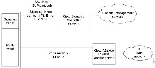
Release 2 Architecture
The protocol stack is illustrated in Table 1.
Extended Q.931 provides call control and maintenance functions. The Q.931 implementation is based on Cisco's National ISDN-2 (NI2), with custom enhancements. The Signaling Controller appears as one or more signaling points in an SS7 network, and performs interworking between the various SS7 protocols in use worldwide to the extended NI2 protocol used between the Cisco SC2200 and NAS.
Q.921 is used to encapsulate the Q.931 messages. It guarantees the in-sequence transmission of Extended Q.931 messages and provides for retransmission. UDP provides for the connectionless transfer of signaling messages across the subnetworks (LAN or WAN), connecting the access servers to the signaling controller.
Benefits
The Cisco SS7/C7 Dial Access Solution System runs on the Cisco AS5300 and Cisco AS5800 access servers in conjunction with Cisco Signaling Controller (CSC) on the Network Access Servers (NAS) to enhance features previously introduced in Cisco IOS release 11.3(5)AA. These features include:
•
•
•
Provided is support for IP connection to SS7/C7 Singnaling Controller and associated continuity testing. This support allows carrier customers to connect their access servers to the Public Switch Telephone Network (PSTN) directly, by using Signaling System #7 (SS7/C7) signaling protocols. The SS7/C7 signaling links terminate on a separate UNIX system called the Signaling Controller (SC2200). The SC2200 maps incoming calls, which are signaled via SS7/C7, to bearers on the access servers. The access servers and SC2200 interact to set up and tear down calls using an extended Q.931 protocol over Q.921 and UDP. In this manner, the access servers and SC2200 form a system that emulates an end-office switch in the PSTN.
The Cisco SS7/C7 Dial Access Solution System uses the ISDN Q.931 and Q.921 protocols over a Redundant Link Manager (RLM) module. RLM makes use of the UDP protocol to transfer information from the NAS to the CSC and vice versa. The ISDN module works in conjunction with the RLM.
Restrictions
The client or server side must support the RLM protocol, which manages those redundant links between the server and client and handles the link and server failover mechanism.
Related Technologies
The Cisco SS7/C7 Dial Access Solution System runs on the Cisco AS5300 and Cisco AS5800 access servers in conjunction with the following Cisco technologies:
•
•
•
Related Documents
•
•
•
•
Supported Platforms
The following hardware platforms support this feature:
•
•
•
•
•
•
Supported Standards, MIBs, and RFCs
Standards
No new or modified standards are supported by this feature.
MIBs
No new or modified MIBs are supported by this feature.
To obtain lists of MIBs supported by platform and Cisco IOS release and to download MIB modules, go to the Cisco MIB web site on Cisco Connection Online (CCO) at http://www.cisco.com/public/sw-center/netmgmt/cmtk/mibs.shtml.
RFCs
No new or modified RFCs are supported by this feature.
Prerequisites
The Cisco AS5350 and Cisco AS5400 do not support the Mica Modem Card, Microcom Modem Card, or VoIP Feature Card. Voice and modem functions are provided by the Universal Port Dial Feature card running SPE firmware. See the Cisco AS5350 Universal Gateway Card Installation Guide and the Cisco AS5400 Universal Gateway Card Installation Guide for more information. All references to the Cisco AS5300 in this document apply to the Cisco AS5350 and Cisco AS5400 platforms with the following exceptions:
•
•
•
Other Prerequisites
We recommend that all access servers use at least two IP interfaces to connect to the primary and alternative IP interfaces of the CSC. Otherwise, the control traffic will be impacted by the data traffic by sharing the same interface for both types of traffic.
Configuration Tasks
See the following sections for configuration tasks for the Redundant Link Manager (RLM) feature. Each task in the list indicates if the task is optional or required.
•
•
Configuring Redundant Link Manager (RLM)
Configure the access server interfaces for Redundant Link Manager.
Verifying RLM
show rlm group status
Enter the show rlm group status command and specify the group number:
Router# show rlm group 1 statusRLM Group 1 StatusUser/Port: RLM_MGR/3000Link State: Up Last Link Status Reported: UpNext tx TID: 1 Last rx TID: 0Server Link Group[r1-server]:link [10.1.1.1(Loopback1), 10.1.4.1] = socket[active]link [10.1.1.2(Loopback2), 10.1.4.2] = socket[standby]Server Link Group[r2-server]:link [10.1.1.1(Loopback1), 10.1.5.1] = socket[opening]link [10.1.1.2(Loopback2), 10.1.5.2] = socket[opening]Note the following:
•
•

Note
show isdn status
Enter the show isdn status command to view layer status information. If ISDN has not been configured, see the document ISDN Module for configuration information.
Router# show isdn statusGlobal ISDN Switchtype = primary-niISDN Serial1:23 interfacedsl 0, interface ISDN Switchtype = primary-ni :Primary D channel of nfas group 0Layer 1 Status:ACTIVELayer 2 Status:TEI = 0, Ces = 1, SAPI = 0, State = MULTIPLE_FRAME_ESTABLISHEDLayer 3 Status:0 Active Layer 3 Call(s)Activated dsl 0 CCBs = 0ISDN Serial2:23 interfacedsl 1, interface ISDN Switchtype = primary-ni :Group member of nfas group 0Layer 1 & 2 Status Not ApplicableLayer 3 Status:0 Active Layer 3 Call(s)Activated dsl 1 CCBs = 0Total Allocated ISDN CCBs = 0Note the following information for Serial 0:23 (the first half of the messages):
•
•
•
The second half of the messages display information for Serial 1:23.
Troubleshooting Tips
If you are having trouble:
•
•
Command Reference
This section documents new or modified commands. All commands used with this feature are documented in the Cisco IOS Release 12.1 command references.
All commands below are used under the top level command, rlm group group-number.
•
clear interface
To reset the hardware logic on an interface, use the clear interface privileged EXEC command.
clear interface name-tag
Syntax Description
name-tag
The logic name to identify the server configuration so that multiple entries of server configuration can be entered.
Command Modes
Privileged EXEC
Command History
11.3(7)
This command first appeared
12.1(5)XM2
The command was introduced for the Cisco AS5350 and CiscoAS5400.
Examples
Router# clear interface loopback 1Router#02:48:52: rlm 1: [State_Up, rx ACTIVE_LINK_BROKEN] over link [10.1.1.1(Loopback1), 10.1.4.1]02:48:52: rlm 1: link [10.1.1.2(Loopback2), 10.1.4.2] requests activation02:48:52: rlm 1: link [10.1.1.1(Loopback1), 10.1.4.1] is deactivated02:48:52: rlm 1: link [10.1.1.1(Loopback1), 10.1.4.1] = socket[10.1.1.1, 10.1.4.1]02:48:52: rlm 1: [State_Recover, rx USER_SOCKET_OPENED] over link [10.1.1.1(Loopback1), 10.1.4.1] for user RLM_MGR02:48:52: rlm 1: link [10.1.1.1(Loopback1), 10.1.4.1] is opened02:48:52: rlm 1: link [10.1.1.1(Loopback1), 10.1.5.1] = socket[10.1.1.1, 10.1.5.1]02:48:52: rlm 1: [State_Recover, rx USER_SOCKET_OPENED] over link [10.1.1.1(Loopback1), 10.1.5.1] for user RLM_MGR02:48:52: rlm 1: link [10.1.1.1(Loopback1), 10.1.5.1] is opened02:48:52: rlm 1: [State_Recover, rx START_ACK] over link [10.1.1.2(Loopback2), 10.1.4.2]02:48:52: rlm 1: link [10.1.1.2(Loopback2), 10.1.4.2] is activated02:48:52: rlm 1: [State_Up, rx LINK_OPENED] over link [10.1.1.1(Loopback1), 10.1.4.1]Router# show rlm group 1 statusRLM Group 1 StatusUser/Port: RLM_MGR/3000Link State: Up Last Link Status Reported: Up_RecoveredNext tx TID: 4 Last rx TID: 0Server Link Group[r1-server]:link [10.1.1.1(Loopback1), 10.1.4.1] = socket[standby, 10.1.1.1, 10.1.4.1]link [10.1.1.2(Loopback2), 10.1.4.2] = socket[active, 10.1.1.2, 10.1.4.2]Server Link Group[r2-server]:link [10.1.1.1(Loopback1), 10.1.5.1] = socket[opening, 10.1.1.1, 10.1.5.1]link [10.1.1.2(Loopback2), 10.1.5.2] = socket[opening, 10.1.1.2, 10.1.5.2]
Router#Router#02:49:52: rlm 1: [State_Up, rx UP_RECOVERED_MIN_TIMEOUT]02:49:52: rlm 1: link [10.1.1.1(Loopback1), 10.1.4.1] requests activation02:49:52: rlm 1: [State_Switch, rx SWITCH_ACK] over link [10.1.1.1(Loopback1), 10.1.4.1]02:49:52: rlm 1: link [10.1.1.2(Loopback2), 10.1.4.2] is deactivated02:49:52: rlm 1: link [10.1.1.1(Loopback1), 10.1.4.1] is activatedRelated Commands
clear rlm group statistics
debug rlm group
interface
link source weight
protocol rlm port
retry keepalive
server
show rlm group statistics
show rlm group status
show rlm group timer
shutdown
timerclear rlm group
To clear all time stamps to zero, use the clear rlm group privileged EXEC command.
clear rlm group group-number link
Syntax Description
Command Modes
Privileged EXEC.
Command History
11.3(7)
This command first appeared
12.1(5)XM2
The command was introduced for the Cisco AS5350 and CiscoAS5400.
Examples
Router# clear rlm group 1 linkRouter#02:48:17: rlm 1: [State_Up, rx ACTIVE_LINK_BROKEN] over link [10.1.1.1(Loopback1), 10.1.4.1]02:48:17: rlm 1: link [10.1.1.2(Loopback2), 10.1.4.2] requests activation02:48:17: rlm 1: link [10.1.1.1(Loopback1), 10.1.4.1] is deactivated02:48:17: rlm 1: [State_Recover, rx LINK_BROKEN] over link [10.1.1.2(Loopback2), 10.1.4.2]02:48:17: rlm 1: link [10.1.1.1(Loopback1), 10.1.4.1] = socket[10.1.1.1, 10.1.4.1]02:48:17: rlm 1: [State_Recover, rx USER_SOCKET_OPENED] over link [10.1.1.1(Loopback1), 10.1.4.1] for user RLM_MGR02:48:17: rlm 1: link [10.1.1.1(Loopback1), 10.1.4.1] is opened02:48:17: rlm 1: link [10.1.1.2(Loopback2), 10.1.4.2] = socket[10.1.1.2, 10.1.4.2]02:48:17: rlm 1: [State_Recover, rx USER_SOCKET_OPENED] over link [10.1.1.2(Loopback2), 10.1.4.2] for user RLM_MGR02:48:17: rlm 1: link [10.1.1.2(Loopback2), 10.1.4.2] is opened02:48:17: rlm 1: link [10.1.1.1(Loopback1), 10.1.5.1] = socket[10.1.1.1, 10.1.5.1]02:48:17: rlm 1: [State_Recover, rx USER_SOCKET_OPENED] over link [10.1.1.1(Loopback1), 10.1.5.1] for user RLM_MGR02:48:17: rlm 1: link [10.1.1.1(Loopback1), 10.1.5.1] is opened02:48:17: rlm 1: link [10.1.1.2(Loopback2), 10.1.5.2] = socket[10.1.1.2, 10.1.5.2]02:48:17: rlm 1: [State_Recover, rx USER_SOCKET_OPENED] over link [10.1.1.2(Loopback2), 10.1.5.2] for user RLM_MGR02:48:17: rlm 1: link [10.1.1.2(Loopback2), 10.1.5.2] is opened02:48:17: rlm 1: [State_Recover, rx LINK_OPENED] over link [10.1.1.1(Loopback1), 10.1.4.1]02:48:17: rlm 1: link [10.1.1.1(Loopback1), 10.1.4.1] requests activation02:48:17: rlm 1: [State_Recover, rx LINK_OPENED] over link [10.1.1.2(Loopback2), 10.1.4.2]02:48:17: rlm 1: [State_Recover, rx START_ACK] over link [10.1.1.1(Loopback1), 10.1.4.1]02:48:17: rlm 1: link [10.1.1.1(Loopback1), 10.1.4.1] is activatedRelated Commands
clear interface
debug rlm group
interface
link source weight
protocol rlm port
retry keepalive
server
show rlm group statistics
show rlm group status
show rlm group timer
shutdown
timerinterface
To define the IP addresses of the server, use the interface command. Each server can have multiple entries of IP addresses or aliases. Use the no form of this command to disable this function.
interface name-tag
no interface name-tag
Syntax Description
name-tag
The logic name to identify the server configuration so that multiple entries of server configuration can be entered.
Defaults
Disabled
Command Modes
Interface configuration
Command History
11.3(7)
This command first appeared
12.1(5)XM2
The command was introduced for the Cisco AS5350 and CiscoAS5400.
Related Commands
clear rlm group statistics
clear interface
debug rlm group
link source weight
protocol rlm port
retry keepalive
server
show rlm group statistics
show rlm group status
show rlm group timer
shutdown
timerlink
To configure preference weighting for one or more entries, use the link command. Within the same server, the link preference is specified in weighting. Use the no form of this command to disable this function.
link { hostname name | address ip-address } source interface weight number
no link { hostname name | address ip-address } source interface weight number
Syntax Description
Defaults
Disabled
Command Modes
RLM configuration
Command History
11.3(7)
This command first appeared
12.1(5)XM2
The command was introduced for the Cisco AS5350 and CiscoAS5400.
Related Commands
clear rlm group statistics
clear interface
debug rlm group
interface
protocol rlm port
retry keepalive
server
show rlm group statistics
show rlm group status
show rlm group timer
shutdown
timerprotocol rlm port
To reconfigured the port number for the basic RLM connectionfor the whole RLM group, use the protocol rlm port command. Use the no form of this command to disable this function.
protocol rlm port port#
no protocol rlm port port#
Syntax Description
port#
Refer to Table 2 below for the default port numbers.
Defaults
3000
Command Modes
RLM configuration
Command History
11.3(7)
This command first appeared
12.1(5)XM2
The command was introduced for the Cisco AS5350 and CiscoAS5400.
Related Commands
clear rlm group statistics
clear interface
debug rlm group
interface
link source weight
retry keepalive
server
show rlm group statistics
show rlm group status
show rlm group timer
shutdown
timerretry keepalive
To configure the number of times the RLM group should retry keepalive failures, use the retry keepalive command. RLM allows keepalive failures in intervals of time before it declares the link is down. Use the no form of this command to disable this function.
retry keepalive number-of-times
no retry keepalive number-of-times
Syntax Description
number-of-times
Number of keepalive failures allowed before the link is declared down, from 1 to 100.
Defaults
3
Command Modes
RLM configuration
Command History
11.3(7)
This command first appeared
12.1(5)XM2
The command was introduced for the Cisco AS5350 and CiscoAS5400.
Related Commands
clear rlm group statistics
clear interface
debug rlm group
interface
link source weight
protocol rlm port
server
show rlm group statistics
show rlm group status
show rlm group timer
shutdown
timerserver
To define the IP addresses of the server for the RLM group, use the server command. Each server can have multiple entries of IP addresses or aliases. Use the no form of this command to disable this function.
server name-tag
no server name-tag
Syntax Description
name-tag
The logic name to identify the server configuration so that multiple entries of server configuration can be entered.
Defaults
Disabled
Command Modes
RLM configuration
Command History
11.3(7)
This command first appeared
12.1(5)XM2
The command was introduced for the Cisco AS5350 and CiscoAS5400.
Related Commands
clear rlm group statistics
clear interface
debug rlm group
interface
link source weight
protocol rlm port
retry keepalive
show rlm group statistics
show rlm group status
show rlm group timer
shutdown
timershow rlm group statistics
To display the network latency of the RLM group, use the show rlm group statistics command.
show rlm group group-number statistics
Syntax Description
Command Modes
Privileged EXEC.
Command History
11.3(7)
This command first appeared
12.1(5)XM2
The command was introduced for the Cisco AS5350 and CiscoAS5400.
Examples
The following is a sample output from the show rlm group group-number statistics command.
Router# show rlm group 1 statisticsRLM Group 1 StatisticsLink_up:last time occurred at 02:45:48.724, total transition=1avg=00:00:00.000, max=00:00:00.000, min=00:00:00.000, latest=00:00:00.000Link_down:last time occurred at 02:42:33.724, total transition=1avg=00:03:15.000, max=00:03:15.000, min=00:00:00.000, latest=00:03:15.000Link_recovered:last time occurred at 00:00:00.000, success=0(0%), failure=0avg=0.000s, max=0.000s, min=0.000s, latest=0.000sLink_switched:last time occurred at 00:00:00.000, success=0(0%), failure=0avg=0.000s, max=0.000s, min=0.000s, latest=0.000sServer_changed:last time occurred at 00:00:00.000 for totally 0 timesServer Link Group[r1-server]:Open the link [10.1.1.1(Loopback1), 10.1.4.1]:last time occurred at 02:43:03.724, success=1(100%), failure=0avg=162.000s, max=162.000s, min=0.000s, latest=162.000sEcho over link [10.1.1.1(Loopback1), 10.1.4.1]:last time occurred at 02:47:15.724, success=91(62%), failure=54avg=0.000s, max=0.000s, min=0.000s, latest=0.000sOpen the link [10.1.1.2(Loopback2), 10.1.4.2]:last time occurred at 02:43:03.724, success=1(100%), failure=0avg=162.000s, max=162.000s, min=0.000s, latest=162.000sEcho over link [10.1.1.2(Loopback2), 10.1.4.2]:last time occurred at 02:47:19.724, success=95(63%), failure=54avg=0.000s, max=0.000s, min=0.000s, latest=0.000sServer Link Group[r2-server]:Open the link [10.1.1.1(Loopback1), 10.1.5.1]:last time occurred at 02:46:06.724, success=0(0%), failure=1avg=0.000s, max=0.000s, min=0.000s, latest=0.000sEcho over link [10.1.1.1(Loopback1), 10.1.5.1]:last time occurred at 02:47:18.724, success=0(0%), failure=85avg=0.000s, max=0.000s, min=0.000s, latest=0.000s
Open the link [10.1.1.2(Loopback2), 10.1.5.2]:last time occurred at 02:46:06.724, success=0(0%), failure=1avg=0.000s, max=0.000s, min=0.000s, latest=0.000sEcho over link [10.1.1.2(Loopback2), 10.1.5.2]:last time occurred at 02:47:18.724, success=0(0%), failure=85avg=0.000s, max=0.000s, min=0.000s, latest=0.000sRouter#
Related Commands
clear rlm group statistics
clear interface
debug rlm group
interface
link source weight
protocol rlm port
retry keepalive
server
show rlm group status
show rlm group timer
shutdown
timershow rlm group status
To display the status of the RLM group, use the show rlm group status command.
show rlm group group-number status
Syntax Description
Command Modes
Privileged EXEC.
Command History
11.3(7)
This command first appeared
12.1(5)XM2
The command was introduced for the Cisco AS5350 and CiscoAS5400.
Examples
The following is a sample output from the show rlm group group-number status command.
Router# show rlm group 1 statusRLM Group 1 StatusUser/Port: RLM_MGR/3000Link State: Up Last Link Status Reported: UpNext tx TID: 1 Last rx TID: 0Server Link Group[r1-server]:link [10.1.1.1(Loopback1), 10.1.4.1] = socket[active]link [10.1.1.2(Loopback2), 10.1.4.2] = socket[standby]Server Link Group[r2-server]:link [10.1.1.1(Loopback1), 10.1.5.1] = socket[opening]link [10.1.1.2(Loopback2), 10.1.5.2] = socket[opening]
Related Commands
clear rlm group statistics
clear interface
debug rlm group
interface
link source weight
protocol rlm port
retry keepalive
server
show rlm group statistics
show rlm group timer
shutdown
timershow rlm group timer
To display the current timer values, use the show rlm group timer command.
show rlm group group-number timer
Syntax Description
Command Modes
Privileged EXEC.
Command History
11.3(7)
This command first appeared
12.1(5)XM2
The command was introduced for the Cisco AS5350 and CiscoAS5400.
Examples
The following is a sample output from the show rlm group group-number timer command.
Router# show rlm group 1 timerRLM Group 1 Timer Valuesopen_wait = 3s force-down = 30srecovery = 12s switch-link = 5sminimum-up = 60s retransmit = 1skeepalive = 1sRouter#
Related Commands
clear rlm group statistics
clear interface
debug rlm group
interface
link source weight
protocol rlm port
retry keepalive
server
show rlm group statistics
show rlm group status
shutdown
timershutdown
To shut down all of the links under the RLM group, use the shutdown command. RLM will not try to reestablish those links until the command is negated. Use the no form of this command to disable this function.
shutdown
no shutdown
Syntax Description
This command has no keywords or arguments.
Defaults
Disabled
Command Modes
RLM configuration
Command History
11.3(7)
This command first appeared
12.1(5)XM2
The command was introduced for the Cisco AS5350 and CiscoAS5400.
Related Commands
clear rlm group statistics
clear interface
debug rlm group
interface
link source weight
protocol rlm port
retry keepalive
server
show rlm group statistics
show rlm group status
show rlm group timer
timertimer
To configure the RLM group timer values, use the timer command. These options can overwrite the default setting of timeout values. The defaults are specified in Table 3 and Table 4. Use the no form of this command to disable this function.
timer {force-down | keepalive | minimum-up | open-wait | recovery | retransmit | switch-link}
time in secondsno timer {force-down | keepalive | minimum-up | open-wait | recovery | retransmit | switch-link} time in seconds
Syntax Description
Defaults
Disabled
Command Modes
RLM configuration
Command History
11.3(7)
This command first appeared
12.1(5)XM2
The command was introduced for the Cisco AS5350 and CiscoAS5400.
Related Commands
clear rlm group statistics
clear interface
debug rlm group
interface
link source weight
protocol rlm port
retry keepalive
server
show rlm group statistics
show rlm group status
show rlm group timer
shutdownDebug Commands
This section describes new debug commands. All other commands used with these features are documented in the Cisco IOS Release 12.1 command references.
debug rlm group
Use the debug rlm group group-number command to display RLM errors. Use the no form of this command to disable debugging output.
debug rlm group group-number { packet echo | event }
no debug rlm group group-number { packet echo | event }
Syntax Description
group-number
RLM group number (0 to 255)
packet echo
Monitors the RLM keepalive on a link.
event
Monitors RLM state changes.
Command History
11.3(7)
This command first appeared
12.1(5)XM2
The command was introduced for the Cisco AS5350 and CiscoAS5400.
Examples
This example shows output of debug rlm group 1 packet echo:
Router# debug rlm group 1 packet echo10:07:44: rlm 1: link [1.14.33.34(Ethernet0), 1.14.33.62] rx ECHO_ACK(tid=35167)10:07:45: rlm 1: link [1.14.33.34(Ethernet0), 1.14.33.62] tx ECHO_REQ(tid=35168)10:07:45: rlm 1: link [1.14.33.34(Ethernet0), 1.14.33.62] rx ECHO_ACK(tid=35168)10:07:46: rlm 1: link [1.14.33.34(Ethernet0), 1.14.33.62] tx ECHO_REQ(tid=35169)10:07:46: rlm 1: link [1.14.33.34(Ethernet0), 1.14.33.62] rx ECHO_ACK(tid=35169)10:07:47: rlm 1: link [1.14.33.34(Ethernet0), 1.14.33.62] tx ECHO_REQ(tid=35170)10:07:47: rlm 1: link [1.14.33.34(Ethernet0), 1.14.33.62] rx ECHO_ACK(tid=35170)10:07:48: rlm 1: link [1.14.33.34(Ethernet0), 1.14.33.62] tx ECHO_REQ(tid=35171)10:07:48: rlm 1: link [1.14.33.34(Ethernet0), 1.14.33.62] rx ECHO_ACK(tid=35171)10:07:49: rlm 1: link [1.14.33.34(Ethernet0), 1.14.33.62] tx ECHO_REQ(tid=35172)10:07:49: rlm 1: link [1.14.33.34(Ethernet0), 1.14.33.62] rx ECHO_ACK(tid=35172)The table describes the significant fields in the debug rlm group 1 packet echo example.
Sample Debug RLM Event Output
Router# debug rlm group 1 event10:09:55: rlm 1: [State_Up, rx ACTIVE_LINK_BROKEN] over link [1.14.33.34(Ethernet0), 1.14.33.62]10:09:58: rlm 1: [State_Recover, rx OPEN_WAIT_TIMEOUT]10:10:01: rlm 1: [State_Recover, rx OPEN_WAIT_TIMEOUT]10:10:04: rlm 1: [State_Recover, rx OPEN_WAIT_TIMEOUT]10:10:07: rlm 1: [State_Recover, rx RECOVERY_TIMEOUT]10:10:07: rlm 1: link [1.14.33.34(Ethernet0), 1.14.33.62] is deactivated10:10:28: %ISDN-6-LAYER2DOWN: Layer 2 for Interface ThunderDial, TEI 0 changed to down10:10:37: rlm 1: [State_Down, rx DOWN_MIN_TIMEOUT]10:10:37: rlm 1: link [1.14.33.34(Ethernet0), 1.14.33.62] = socket[1.14.33.34, 1.14.33.62]10:10:37: rlm 1: [State_Down, rx USER_SOCKET_OPENED] over link [1.14.33.34(Ethernet0), 1.14.33.62] for user RLM_MGR10:10:37: rlm 1: link [1.14.33.34(Ethernet0), 1.14.33.62] is opened10:10:37: rlm 1: link [1.14.33.34(Ethernet0), 1.14.33.62] = socket[1.14.33.34, 1.14.33.62]10:10:37: rlm 1: [State_Down, rx USER_SOCKET_OPENED] over link [1.14.33.34(Ethernet0), 1.14.33.62] for user ISDN10:10:37: rlm 1: [State_Down, rx LINK_OPENED] over link [1.14.33.34(Ethernet0), 1.14.33.62]10:10:40: rlm 1: [State_Down, rx OPEN_WAIT_TIMEOUT]10:10:40: rlm 1: link [1.14.33.34(Ethernet0), 1.14.33.62] requests activation10:10:40: rlm 1: [State_Down, rx START_ACK] over link [1.14.33.34(Ethernet0), 1.14.33.62]10:10:40: rlm 1: link [1.14.33.34(Ethernet0), 1.14.33.62] is activated10:10:43: %ISDN-6-LAYER2UP: Layer 2 for Interface, TEI 0 changed to upRouter#The table describes the significant fields in the debug rlm group 1 event example.
RLM Default Timing and Countdown Values
Table 3
RLM Default Timing Values
Table 4
rlm_link_echo_retry
3
Allow certain number of consecutive echo failures before failover.
RLM Default Countdown Values
Glossary
CSC—Cisco Signaling Controller. A server which interfaces between the NAS and the SS7 signaling network.
COT—Continuity test. Used to test individual DS0 channels via either loopback or tone detection and generation.
DSP—Digital Signal Processor. Many firmware functions of a NAS are performed by DSPs which are generally provisioned as banks of shared resources among all the DS0s. Typical DSP functions include: data modems, voice CODECS, fax modems and CODECs, and low-level signaling (such as CAS/R2).
HDLC—High-Level Data Link Control.
ISP—Internet service provider.
NAS—Network access server. A Cisco platform (or collection of platforms such as an AccessPath system which interfaces between the packet world (for example, the Internet) and the circuit world (for example, the PSTN).
PSTN—Public Switched Telephone Network.
SS7—Signaling System Number 7.
SSP—Service switching point. An element of an SS7-based Intelligent Network which performs call origination, termination, or tandem switching. The combined NAS/CSC system looks like a single SSP to the SS7 network.
STP—Signal transfer point. An element of an SS7-based Intelligent Network which performs routing of the SS7 signaling.
T1—A digital carrier used to transmit a DS-1 formatted digital signal at 1.544 MHz.
TDM—Time-division multiplexing. The transmission scheme employed by all digital circuits in the PSTN.
RLM—Redundant link manager.
UDP—User Datagram Protocol.
VoIP—Voice over IP. The ability to carry normal telephony-style voice over an IP-based Internet with POTS-like functionality, reliability, and voice quality.
Note
 Feedback