Feedback Feedback
|
Table Of Contents
Upgrading Cisco AS5300 Voice-over-IP Feature Card VCWare
Install TFTP Application on PC
Replace Firmware with VCWare in VCWare Mode
Replace Firmware with VCWare in ROM Monitor Mode
Upgrading Cisco AS5300 Voice-over-IP Feature Card VCWare
Product Numbers: AS53-CC-VOX=, AS53-6VOX=, AS53-CC-VOX, AS53-6VOX
When Cisco upgrades the Voice-over-IP (VoIP) feature card (VFC) firmware, called VCWare, you can download the upgrade from Cisco. Use the procedures documented in this section to upgrade your Voice feature card VCWare.
Before downloading a new version of VCWare, be sure to verify that the version of VCWare is compatible with the specific release of Cisco IOS software already running on the access server. A compatibility matrix is posted on Cisco Connection Online's Software Center (see Step 2 of the "Install TFTP Application on PC" section for the URL).
Note
In certain countries, use of these products or provisions of voice telephony over the Internet may be prohibited and/or subject to laws, regulations or licenses, including requirements applicable to the use of the products under telecommunications and other laws and regulations; customer must comply with all such applicable laws in the country(ies) where customer intends to use the product.
This document includes the following sections:
Before Upgrading VCWare
This section provides example instructions for how to upgrade Voice feature card (VFC) VCWare using a PC. If you are not in a PC environment, use the procedures as general guidelines; the steps are similar.
The upgrade procedure consists of the following tasks:
•
Install TFTP Application on PC
This section provides instructions for installing a TFTP application on your PC to transfer the latest VCWare file. Ignore this section if:
•
•
•
•
Note
Step 1
Step 2
Note
Step 3
Step 4
Step 5
Step 6
Step 7
(a)
(b)
(c)
Caution
Step 8
Note
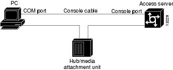
Connect PC and Access Server
Use the steps in this section to connect your PC to the access server. If you are not using a PC, skip this section, or use the procedure as a guideline.
Step 1
Figure 1 Connecting PC and Access Server
Step 2
Step 3
Step 4
Establish Console Session
Use the steps in this section to establish a console session from your local PC to the Cisco AS5300. You will use this session to talk to the access server. If you are not using a PC, skip this section, or use the procedure as a guideline.
Note
Step 1
Step 2
Step 3
Step 4
Step 5
Step 6
•
•
•
•
•
Step 7
Note
Step 8
5300> enablePassword: <password>5300#Enable mode provides access to privileged commands.
Step 9
Ping PC and Access Server
Use the steps in this section to ping the access server and the PC to verify that they are talking to each other and that there are no configuration problems on your access server. If you are not using a PC, skip this section, or use the procedure as a guideline.
Note
Step 1
(a)
(b)
(c)
(d)
Note
Step 2
Step 3
5300# ping XXX.XXX.XXX.XXXThe access server displays five exclamation points (!) if everything is working and it displays five dots (.) if there is a problem. If there is a problem, check the cabling between the router and the PC and check the access server configuration.
Step 4
Upgrade VCWare
To upgrade VCWare, you need to:
2
or
Replace Firmware with VCWare in ROM Monitor ModeSee the following sections for details.
Identify Voice Cards
Use the following steps to determine which slots have voice cards installed and in what mode each voice card is running:
Step 1
You should see the enable mode prompt (5300#). If not, enter enable mode now (see "Establish Console Session" for details).
Step 1
5300> enablePassword: <password>5300#Step 2
The voice cards run in either VCWare mode or ROM Monitor mode.
5300# show vfc <0-2> boardNo voice board in slot 0.VFC board state is UP, vfc status VCWARE running(0x4)VFC board in slot 1 with 18 dspsNo voice board in slot 2.In the example above, only slot 1 has a voice card installed and it is running in VCWare mode.
Step 3
Step 4
Replace Firmware with VCWare in VCWare Mode
Use the steps that follow to download new voice software if your voice card is running in VCWare mode. When downloading from a diskette, first copy the software from the diskette to a TFTP server. After the software is on the TFTP server, begin the steps in the Configure section.
CautionErasing the VFC files can result in system outage or the corruption of your VFC board. Check to ensure that the correct version of software resides on your TFTP server before continuing.
Configure
Step 1
5300# erase vfc 1Step 2
This will erase the contents of VFC Flash. Continue ?[y/n]: yThis will take some time. Please, wait...vfcStep 3
5300# show vfc 1 directoryFiles in slot 1 VFC flash:File Name Size (Bytes)The Flash memory is empty if no filename or size is listed.
Step 4
5300# copy tftp: vfc:Step 5
Voice card slot number <slot ? 1>Step 6
Address or name of remote host [UNKNOWN]? 223.255.30.30Step 7
Source file name? vcw-vfc-mz.1.0.bin
Note
Step 8
Destination file name [vcw-vfc-mz.1.0.bin]? vcw-vfc-mz.1.0.binAfter entering this filename you will see the following output:
Accessing file 'vcw-vfc-mz.1.0.bin' on 223.255.30.30...Loading vcw-vfc-mz.1.0.bin from 223.255.30.30 (via Ethernet0):!!!!!!!!!!!!!!!!!!!!!!!!!!!!!!!!!!!!!!!!!!!!!!!!!!!!!!!!!!!!!!!!!!!!!!!!!!!!!!!!!!!![OK - 292972/349696 bytes]Step 9
5300# clear vfc 1Step 10
Do you really want to reset this card ? [y/n] yPlease, wait...Voice Feature Card in slot 1 is down.Voice Feature Card in slot 1 is reset.5300#Voice Feature Card in slot 1 is up.Step 11
5300> enablePassword: <password>5300#Step 12
Note
5300# show vfc 1 boardVFC board state is UP, vfc status VCWARE running(0x4)VFC board in slot 1 with 18 dspsStep 13
5300# show vfc 1 directoryFiles in slot 1 VFC flash:File Name Size (Bytes)1. vcw-vfc-mz.1.0.bin 292972Step 14
5300# unbundle vfc 1this will unbundle the current RUNNING image of VFC Softwareand NOT the image on VFC Flash.After unbundling, you may need to reload the Router.Step 15
Do you want to continue ? [y/n]: yPlease, wait...Slot 1. Unbundling done. You may need to reload the Router.Step 16
5300# show vfc 1 directoryFiles in slot 1 VFC flash:File Name Size (Bytes)1. vcw-vfc-mz_1._0.bin 2929722. bt1-vfc-l.1.0.bin 41743. cor-vfc-l.1.0.bin 548804. jbc-vfc-l.1.0.bin 167605. fax-vfc-l.1.0.bin 644186. bas-vfc-l.1.0.bin 547567. cdc-g711-l.1.0.bin 1908. cdc-g729-l.1.0.bin 21002Step 17
5300# show vfc 1 default-fileDefault File List for VFC in slot 1:1. bt1-vfc-l.1.0.bin2. cor-vfc-l.1.0.bin3. bas-vfc-l.1.0.bin4. cdc-g729-l.1.0.bin5. fax-vfc-l.1.0.bin6. jbc-vfc-l.1.0.binStep 18
5300# show vfc 1 cap-listCapability List for VFC in slot 1:1. fax-vfc-l.1.0.bin2. bas-vfc-l.1.0.bin3. cdc-g729-l.1.0.bin4. cdc-g711-l.1.0.binStep 19
Step 20
5300# reload
Proceed with reload? [confirm]
Verify
To check that you have successfully downloaded the software:
•
5300# show vfc 1 dirFiles in slot 1 VFC flash:File Name Size (Bytes)1. vcw-vfc-mz.1.0.bin 291292•
5300# show vfc 1 default-fileDefault File List for VFC in slot 1:1. bt1-vfc-l.1.0.bin2. cor-vfc-l.1.0.bin3. bas-vfc-l.1.0.bin4. cdc-g729-l.1.0.bin5. fax-vfc-l.1.0.bin6. jbc-vfc-l.1.0.bin5300# show vfc 1 cap-listCapability List for VFC in slot 1:1. fax-vfc-l.1.0.bin2. bas-vfc-l.1.0.bin3. cdc-g729-l.1.0.bin4. cdc-g711-l.1.0.bin5300#Tips
If you are having trouble downloading the voice feature card software in VCWare mode, try the following:
•
5300# show vfc 1 boardVFC board state is UP, vfc status VCWARE running(0x4)VFC board in slot 1 with 18 dsps5300#•
5300# sh vfc 1 ver vcwVoice Feature Card in Slot 1:VCware Version : 1.0ROM Monitor Version: 1.2DSPware Version : 1.0•
Replace Firmware with VCWare in ROM Monitor Mode
Use the steps that follow to download new voice software if your voice card is running in ROM Monitor mode. When downloading from a diskette, first copy the software from the diskette to a TFTP server. After the software is on the TFTP server, begin the steps in the following "Configure" section.
CautionErasing the VFC files can result in system outage or the corruption of your VFC board. Check to ensure that the correct version of software resides on your TFTP server before continuing.
Configure
Step 1
5300# clear vfc 1 purgedebug vfc <slot#> startdebug vfc <slot#> cons flash eraseStep 2
This will erase the contents of VFC Flash. Continue ?[y/n]: yThis will take some time. Please, wait...vfcStep 3
5300# copy tftp: vfc:Step 4
Voice card slot number <slot ? 1>Step 5
Address or name of remote host [UNKNOWN]? 223.255.30.30Step 6
Source file name? vcw-vfc-mz.1.0.bin
Note
Step 7
Destination file name [vcw-vfc-mz.1.0.bin]? vcw-vfc-mz.1.0.binWhen this filename is entered, you will see:
Accessing file 'vcw-vfc-mz.1.0.bin' on 223.255.30.30...Loading vcw-vfc-mz.1.0.bin from 223.255.30.30 (via Ethernet0):!!!!!!!!!!!!!!!!!!!!!!!!!!!!!!!!!!!!!!!!!!!!!!!!!!!!!!!!!!!!!!!!!!!!!!!!!!!!!!!!!!!![OK - 292972/349696 bytes]Step 8
5300# clear vfc 1Step 9
Do you really want to reset this card ? [y/n] yPlease, wait...Voice Feature Card in slot 1 is down.Voice Feature Card in slot 1 is reset.5300#Voice Feature Card in slot 1 is up.Step 10
5300> enablePassword: <password>5300#Step 11
5300# show vfc 1 boardVFC board state is UP, vfc status VCWARE running(0x4)VFC board in slot 1 with 18 dspsStep 12
5300# show vfc 1 directoryFiles in slot 1 VFC flash:File Name Size (Bytes)1. vcw-vfc-mz.1.0.bin 292972Step 13
5300# unbundle vfc 1this will unbundle the current RUNNING image of VFC Softwareand NOT the image on VFC Flash.After unbundling, you may need to reload the Router.Step 14
Do you want to continue ? [y/n]: yPlease, wait...Slot 1. Unbundling done. You may need to reload the Router.Step 15
5300# show vfc 1 directoryFiles in slot 1 VFC flash:File Name Size (Bytes)1. vcw-vfc-mz_1._0.bin 2929722. bt1-vfc-l.1.0.bin 41743. cor-vfc-l.1.0.bin 548804. jbc-vfc-l.1.0.bin 167605. fax-vfc-l.1.0.bin 644186. bas-vfc-l.1.0.bin 547567. cdc-g711-l.1.0.bin 1908. cdc-g729-l.1.0.bin 21002Step 16
5300# show vfc 1 default-fileDefault File List for VFC in slot 1:1. bt1-vfc-l.1.0.bin2. cor-vfc-l.1.0.bin3. bas-vfc-l.1.0.bin4. cdc-g729-l.1.0.bin5. fax-vfc-l.1.0.bin6. jbc-vfc-l.1.0.binStep 17
5300# show vfc 1 cap-listCapability List for VFC in slot 1:1. fax-vfc-l.1.0.bin2. bas-vfc-l.1.0.bin3. cdc-g729-l.1.0.bin4. cdc-g711-l.1.0.binStep 18
Step 19
5300# reload
Proceed with reload? [confirm]
Verify
To check that you have successfully downloaded the software:
•
5300# show vfc 1 dirFiles in slot 1 VFC flash:File Name Size (Bytes)1. vcw-vfc-mz.1.0.bin 291292•
5300# show vfc 1 default-fileDefault File List for VFC in slot 1:1. bt1-vfc-l.1.0.bin2. cor-vfc-l.1.0.bin3. bas-vfc-l.1.0.bin4. cdc-g729-l.1.0.bin5. fax-vfc-l.1.0.bin6. jbc-vfc-l.1.0.bin5300# show vfc 1 cap-listCapability List for VFC in slot 1:1. fax-vfc-l.1.0.bin2. bas-vfc-l.1.0.bin3. cdc-g729-l.1.0.bin4. cdc-g711-l.1.0.bin5300#Tips
If you are having trouble downloading the voice feature card software in ROM Monitor mode, try the following:
•
5300# show vfc 1 boardVFC board state is UP, vfc status VCWARE running(0x4)VFC board in slot 1 with 18 dsps5300#•
5300# sh vfc 1 ver vcwVoice Feature Card in Slot 1:VCware Version : 1.0ROM Monitor Version: 1.2DSPware Version : 1.0This completes the Cisco Voice over IP VCWare upgrading procedure. For more information about related documents and services, and for customer support, see the "Related Documentation" section and the "Cisco Connection Online" section.
Related Documentation
For more information, refer to the following documents:
•
•
•
•
New Hardware Features
Hardware features available after the release of this document are found at the following URL:
http://www.cisco.com/univercd/cc/td/doc/product/access/acs_serv/5300/5300cfg/index.htm
Documentation CD-ROM
Cisco documentation and additional literature are available in a CD-ROM package, which ships with your product. The Documentation CD-ROM, a member of the Cisco Connection Family, is updated monthly. Therefore, it might be more current than printed documentation. To order additional copies of the Documentation CD-ROM, contact your local sales representative or call customer service. The CD-ROM package is available as a single package or as an annual subscription. You can also access Cisco documentation on the World Wide Web at http://www.cisco.com, http://www-china.cisco.com, or http://www-europe.cisco.com.
If you are reading Cisco product documentation on the World Wide Web, you can submit comments electronically. Click Feedback in the toolbar and select Documentation. After you complete the form, click Submit to send it to Cisco. We appreciate your comments.
Cisco Connection Online
Cisco Connection Online (CCO) is Cisco Systems' primary, real-time support channel. Maintenance customers and partners can self-register on CCO to obtain additional information and services.
Available 24 hours a day, 7 days a week, CCO provides a wealth of standard and value-added services to Cisco's customers and business partners. CCO services include product information, product documentation, software updates, release notes, technical tips, the Bug Navigator, configuration notes, brochures, descriptions of service offerings, and download access to public and authorized files.
CCO serves a wide variety of users through two interfaces that are updated and enhanced simultaneously: a character-based version and a multimedia version that resides on the World Wide Web (WWW). The character-based CCO supports Zmodem, Kermit, Xmodem, FTP, and Internet e-mail, and it is excellent for quick access to information over lower bandwidths. The WWW version of CCO provides richly formatted documents with photographs, figures, graphics, and video, as well as hyperlinks to related information.
You can access CCO in the following ways:
•
•
•
•
•
For a copy of CCO's Frequently Asked Questions (FAQ), contact cco-help@cisco.com. For additional information, contact cco-team@cisco.com.
Note
78-5463-01