 Feedback Feedback
|
Table Of Contents
Cisco AS5300 Voice-over-IP Feature Card Installation and Configuration
Preventing Electrostatic Discharge Damage
Installation and Removal Procedures
Prerequisites to Configuration
Step 1: Configuring IP Networks for Real-Time Voice Traffic
Step 2: Configuring Voice Ports for ISDN PRI
Step 3: Configuring the D Channels
Step 4: Configuring the Dial Peers
Step 5: Configuring Voice Network Data
Upgrading VoIP Feature Card VCWare
Replace Firmware with VCWare in VCWare Mode
Replace Firmware with VCWare in ROM Monitor Mode
Cisco AS5300 Voice-over-IP Feature Card Installation and Configuration
Product Numbers: AS53-CC-VOX=, AS53-6VOX=, AS53-CC-VOX, AS53-6VOX
The Voice-over-IP (VoIP) Feature Card is a coprocessing card and software package that adds VoIP capabilities to Cisco AS5300 universal access servers. The VoIP capability enables a Cisco router to carry live voice traffic (for example, telephone calls and faxes) over an IP network. The VoIP feature card is available as a spare or a factory-installed card within the chassis.
The VoIP feature card contains multiple digital signal processor (DSP) modules. It uses the Cisco AS5300's quad T1/E1 Public Switched Telephone Network (PSTN) interface and local-area network (LAN) or wide-area network (WAN) routing capabilities to provide up to a 48/60 channel gateway for VoIP packetized voice traffic to/from T1/E1 time-division multiplexing (TDM) traffic. Major applications of the VoIP feature cards include toll bypass, remote PBX presence over WANs, unified voice/data trunking, and plain old telephone service (POTS) internet phone gateway. If you purchased a chassis with this card already installed go directly to "Prerequisites to Configuration" on page 12 .
Note
In certain countries, use of these products or provision of voice telephony over the Internet may be prohibited and/or subject to laws, regulations or licenses, including requirements applicable to the use of the products under telecommunications and other laws and regulations; customer must comply with all such applicable laws in the country(ies) where customer intends to use the product.
This document includes the following sections:
•
•
•
•
•
•
•
•
•
•
•
•
•
Applications
VoIP offers the following benefits:
•
•
•
•
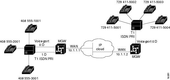
The VoIP feature card has two primary applications. The first application (see Figure 1) provides a central-site telephony termination facility for VoIP traffic from multiple voice-equipped Cisco AS5300 remote office facilities.
Figure 1 VoIP Feature Card as Central Site
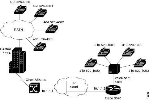
The second application (see Figure 2) uses the VoIP feature card as a PSTN gateway for Internet telephone traffic. This leverages the standardized use of H.323-based Internet telephone client applications.
Figure 2 VoIP Feature Card as Internet Telephone to PSTN Gateway
Hardware Features
The basic hardware features of the VoIP feature card and the DSP modules are described in the following sections.
Note
VoIP Feature Card
The VoIP feature card is a voice processing card that resides in one of the slots in the Cisco AS5300 universal access server. Up to five DSP modules can be installed onto the Voice feature card to perform voice processing for up to 30 B channels.
•
•
•
•
•
DSP Modules
The DSP module provides voice compression and packetization services to the Voice feature card in a configurable and expandable fashion.
•
•
•
CautionDo not mix DSP modules on the same voice card. You cannot install a DSP 549 double-density module and a DSP 542 module on the same voice card, nor can you mix a voice card carrying only DSP 549 modules and a voice card carrying only DSP 542 modules in the same chassis.
Prerequisites
You need to have available the Cisco Documentation CD-ROM, printed documents or web access to: Cisco AS5300 Universal Access Server Software Configuration Guide, Cisco AS5300 Universal Access Server Hardware Installation Guide, Voice Over IP for Cisco AS5300 Software Configuration Guide, and the Regulatory Compliance and Safety Information document for the AS5300 universal access server.
Before you can configure your Cisco AS5300 to use Voice over IP, you must first:
•
•
•
•
•
•
For more information about any of these configuration tasks, refer to the Cisco AS5300 Universal Access Server Software Configuration Guide.
•
•
•
•
•
•
•
Safety Recommendations
Follow these guidelines to ensure general safety:
•
•
•
•
•
•
Safety Warnings
Safety warnings appear throughout this publication in procedures that, if performed incorrectly, may harm you. A warning symbol precedes each safety warning.
Warning
This warning symbol means danger. You are in a situation that could cause bodily injury. Before you work on any equipment, be aware of the hazards involved with electrical circuitry and be familiar with standard practices for preventing accidents. To see translations of the warnings that appear in this publication, refer to the Regulatory Compliance and Safety Information document that accompanied this device.
Waarschuwing Dit waarschuwingssymbool betekent gevaar. U verkeert in een situatie die lichamelijk letsel kan veroorzaken. Voordat u aan enige apparatuur gaat werken, dient u zich bewust te zijn van de bij elektrische schakelingen betrokken risico's en dient u op de hoogte te zijn van standaard maatregelen om ongelukken te voorkomen. Voor vertalingen van de waarschuwingen die in deze publicatie verschijnen, kunt u het document Regulatory Compliance and Safety Information (Informatie over naleving van veiligheids- en andere voorschriften) raadplegen dat bij dit toestel is ingesloten.
Varoitus Tämä varoitusmerkki merkitsee vaaraa. Olet tilanteessa, joka voi johtaa ruumiinvammaan. Ennen kuin työskentelet minkään laitteiston parissa, ota selvää sähkökytkentöihin liittyvistä vaaroista ja tavanomaisista onnettomuuksien ehkäisykeinoista. Tässä julkaisussa esiintyvien varoitusten käännökset löydät laitteen mukana olevasta Regulatory Compliance and Safety Information -kirjasesta (määräysten noudattaminen ja tietoa turvallisuudesta).
Attention Ce symbole d'avertissement indique un danger. Vous vous trouvez dans une situation pouvant causer des blessures ou des dommages corporels. Avant de travailler sur un équipement, soyez conscient des dangers posés par les circuits électriques et familiarisez-vous avec les procédures couramment utilisées pour éviter les accidents. Pour prendre connaissance des traductions d'avertissements figurant dans cette publication, consultez le document Regulatory Compliance and Safety Information (Conformité aux règlements et consignes de sécurité) qui accompagne cet appareil.
Warnung Dieses Warnsymbol bedeutet Gefahr. Sie befinden sich in einer Situation, die zu einer Körperverletzung führen könnte. Bevor Sie mit der Arbeit an irgendeinem Gerät beginnen, seien Sie sich der mit elektrischen Stromkreisen verbundenen Gefahren und der Standardpraktiken zur Vermeidung von Unfällen bewußt. Übersetzungen der in dieser Veröffentlichung enthaltenen Warnhinweise finden Sie im Dokument Regulatory Compliance and Safety Information (Informationen zu behördlichen Vorschriften und Sicherheit), das zusammen mit diesem Gerät geliefert wurde.
Avvertenza Questo simbolo di avvertenza indica un pericolo. La situazione potrebbe causare infortuni alle persone. Prima di lavorare su qualsiasi apparecchiatura, occorre conoscere i pericoli relativi ai circuiti elettrici ed essere al corrente delle pratiche standard per la prevenzione di incidenti. La traduzione delle avvertenze riportate in questa pubblicazione si trova nel documento Regulatory Compliance and Safety Information (Conformità alle norme e informazioni sulla sicurezza) che accompagna questo dispositivo.
Advarsel Dette varselsymbolet betyr fare. Du befinner deg i en situasjon som kan føre til personskade. Før du utfører arbeid på utstyr, må du vare oppmerksom på de faremomentene som elektriske kretser innebærer, samt gjøre deg kjent med vanlig praksis når det gjelder å unngå ulykker. Hvis du vil se oversettelser av de advarslene som finnes i denne publikasjonen, kan du se i dokumentet Regulatory Compliance and Safety Information (Overholdelse av forskrifter og sikkerhetsinformasjon) som ble levert med denne enheten.
Aviso Este símbolo de aviso indica perigo. Encontra-se numa situação que lhe poderá causar danos físicos. Antes de começar a trabalhar com qualquer equipamento, familiarize-se com os perigos relacionados com circuitos eléctricos, e com quaisquer práticas comuns que possam prevenir possíveis acidentes. Para ver as traduções dos avisos que constam desta publicação, consulte o documento Regulatory Compliance and Safety Information (Informação de Segurança e Disposições Reguladoras) que acompanha este dispositivo.
¡Advertencia! Este símbolo de aviso significa peligro. Existe riesgo para su integridad física. Antes de manipular cualquier equipo, considerar los riesgos que entraña la corriente eléctrica y familiarizarse con los procedimientos estándar de prevención de accidentes. Para ver una traducción de las advertencias que aparecen en esta publicación, consultar el documento titulado Regulatory Compliance and Safety Information (Información sobre seguridad y conformidad con las disposiciones reglamentarias) que se acompaña con este dispositivo.
Varning! Denna varningssymbol signalerar fara. Du befinner dig i en situation som kan leda till personskada. Innan du utför arbete på någon utrustning måste du vara medveten om farorna med elkretsar och känna till vanligt förfarande för att förebygga skador. Se förklaringar av de varningar som förkommer i denna publikation i dokumentet Regulatory Compliance and Safety Information (Efterrättelse av föreskrifter och säkerhetsinformation), vilket medföljer denna anordning.
Safety with Electricity
Warning
Read the installation instructions before you connect the system to its power source.
Warning
Ultimate disposal of this product should be handled according to all national laws and regulations.
Warning
Before working on a chassis or working near power supplies, unplug the power cord on AC units; disconnect the power at the circuit breaker on DC units.
Warning
To ensure your safety and the safety of others, be sure the power is OFF and the power cord is unplugged before working on the router.
Warning
Before working on equipment that is connected to power lines, remove jewelry (including rings, necklaces, and watches). Metal objects will heat up when connected to power and ground and can cause serious burns or weld the metal object to the terminals.
Follow these guidelines when working on equipment powered by electricity:
•
•
•
•
•
•
•
•
•
•
•
•
Preventing Electrostatic Discharge Damage
Electrostatic discharge (ESD) can damage equipment and impair electrical circuitry. It occurs when electronic printed circuit cards are improperly handled and can result in complete or intermittent failures. Always follow ESD prevention procedures when removing and replacing cards. Ensure that the chassis is electrically connected to earth ground. Wear an ESD-preventive wrist strap, ensuring that it makes good skin contact. Connect the clip to an unpainted surface of the chassis frame to safely channel unwanted ESD voltages to ground. To properly guard against ESD damage and shocks, the wrist strap and cord must operate effectively. If no wrist strap is available, ground yourself by touching the metal part of the chassis.
CautionFor safety, periodically check the resistance value of the antistatic strap, which should be between 1 and 10 megohm (Mohm).
Software Requirements
In the Cisco AS5300 universal access server, the VoIP feature card and the DSP modules require Cisco IOS Release IP Plus SF53CP-11.3.2N or higher.
Required Tools and Equipment
To install or remove the VoIP feature card and the DSP modules, you will need the following tools and equipment, which are not included:
•
•
•
•
•
•
VoIP Feature Card Indicators
The LEDs on the front panel of the VoIP feature card (see Figure 3) indicate the current operating condition of the DSP modules installed on the card. You can observe the LEDs, note any fault condition, and then contact your system administrator or a customer service representative, if necessary. See the "Cisco Connection Online" section for information on contacting customer service. Refer to Table 1 for a description of the LEDs.
Figure 3 VoIP Feature Card LEDs
Table 1 VoIP Feature Card LEDs
Activity (ACT)1
Flickering
There is call activity on the DSP modules.
Off
There is no call activity on the DSP modules.
Board OK (OK)
One flash
The VoIP feature card is powering up.
On
The VoIP feature card has passed initial power-up diagnostics tests and is operating normally.
Off
A fault condition occurred.
1 The individual DSP modules do not include LEDs.
Installation and Removal Procedures
This section contains the following procedures:
•
Removing VoIP Feature Cards
This section describes how to remove a VoIP feature card.
Warning


To remove the VoIP feature card, perform the following steps:
Step 1 ![]() Attach an ESD-preventive wrist strap.
Attach an ESD-preventive wrist strap.
Step 2 ![]() Power OFF the access server.
Power OFF the access server.
Step 3 ![]() On the rear panel of the access server, locate the VoIP feature card seen in Figure 3.
On the rear panel of the access server, locate the VoIP feature card seen in Figure 3.
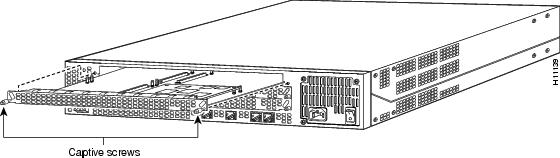
Step 4 ![]() Loosen the two captive screws that secure the VoIP feature card to the chassis until each screw is free of the chassis (see Figure 4).
Loosen the two captive screws that secure the VoIP feature card to the chassis until each screw is free of the chassis (see Figure 4).
Figure 4 VoIP Feature Card Removal
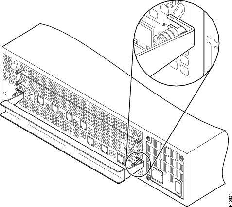
Step 5 ![]() Insert the feature card removal tool so that the slots in each arm of the tool are behind the shoulder of each captive screw, as shown in Figure 5, and carefully pull the removal tool toward you until the VoIP feature card slides free of the chassis.
Insert the feature card removal tool so that the slots in each arm of the tool are behind the shoulder of each captive screw, as shown in Figure 5, and carefully pull the removal tool toward you until the VoIP feature card slides free of the chassis.
Figure 5 Removing VoIP Feature Card
Step 6 ![]() Set the removed VoIP feature card aside on an ESD-preventive mat.
Set the removed VoIP feature card aside on an ESD-preventive mat.
Removing DSP Modules
To remove DSP modules:
Step 1 ![]() Make sure that you have attached an ESD-preventive wrist strap and that the system is powered OFF.
Make sure that you have attached an ESD-preventive wrist strap and that the system is powered OFF.
Step 2 ![]() On the VoIP feature card, locate the DSP module you will replace (see Figure 6).
On the VoIP feature card, locate the DSP module you will replace (see Figure 6).
Figure 6 Removing DSP Modules

Step 3 ![]() Orient the VoIP feature card so that the DSP module socket is facing toward you.
Orient the VoIP feature card so that the DSP module socket is facing toward you.
Step 4 ![]() Gently pry the front edge of the DSP module away from the standoffs and the socket, as indicated by the arrow labeled 1 in Figure 6.
Gently pry the front edge of the DSP module away from the standoffs and the socket, as indicated by the arrow labeled 1 in Figure 6.
Step 5 ![]() When the DSP module is free of the socket, gently pry the back edge of the DSP module away from the other set of standoffs, as indicated by the arrow labeled 2 in Figure 6.
When the DSP module is free of the socket, gently pry the back edge of the DSP module away from the other set of standoffs, as indicated by the arrow labeled 2 in Figure 6.
Installing DSP Modules
To install a DSP module, first seat the DSP module in the socket, then press all four corners onto their respective standoffs, as shown in Figure 7.
Figure 7 Installing DSP Modules
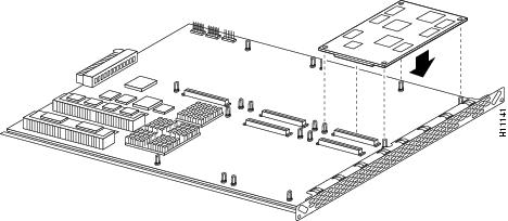

Note ![]() Mate the socket on the DSP module with the socket on the VoIP feature card.
Mate the socket on the DSP module with the socket on the VoIP feature card.
Installing VoIP Feature Cards
To install a VoIP feature card:
Step 1 ![]() Remove the VoIP feature card from the ESD-preventive mat.
Remove the VoIP feature card from the ESD-preventive mat.
Step 2 ![]() Slide the VoIP feature card into the slot until it touches the backplane connector.
Slide the VoIP feature card into the slot until it touches the backplane connector.
Step 3 ![]() Align the captive screws with their holes, and then seat the VoIP feature card completely.
Align the captive screws with their holes, and then seat the VoIP feature card completely.
Step 4 ![]() Tighten the two captive screws (see Figure 8) to secure the VoIP feature card to the chassis.
Tighten the two captive screws (see Figure 8) to secure the VoIP feature card to the chassis.
Figure 8 Installing the VoIP Feature Card
Step 5 ![]() If the access server is configured with fewer than three feature cards, make sure that a blank slot cover is installed over each open slot to ensure proper airflow inside the chassis.
If the access server is configured with fewer than three feature cards, make sure that a blank slot cover is installed over each open slot to ensure proper airflow inside the chassis.
Prerequisites to Configuration
Before you can configure your Cisco router to use VoIP, you must first:
•![]() Establish a working IP network. For more information about configuring IP, refer to the "Configuring IP" chapter in the Cisco IOS Release 11.2 Network Protocols Configuration Guide, Part 1.
Establish a working IP network. For more information about configuring IP, refer to the "Configuring IP" chapter in the Cisco IOS Release 11.2 Network Protocols Configuration Guide, Part 1.
•![]() Install the voice network module into the appropriate bay of your Cisco router. For more information about the physical characteristics of the voice network module, or how to install it, refer to the section "Installation and Removal Procedures" in this document.
Install the voice network module into the appropriate bay of your Cisco router. For more information about the physical characteristics of the voice network module, or how to install it, refer to the section "Installation and Removal Procedures" in this document.
•![]() Complete your company's dial plan.
Complete your company's dial plan.
•![]() Establish a working telephony network based on your company's dial plan.
Establish a working telephony network based on your company's dial plan.
•![]() Integrate your dial plan and telephony network into your existing IP network topology.
Integrate your dial plan and telephony network into your existing IP network topology.
Configuring VoIP
The actual configuration procedure depends entirely upon the topology of your voice network, but, in general, you need to complete the following tasks:
•![]() Step 1: Configuring IP Networks for Real-Time Voice Traffic
Step 1: Configuring IP Networks for Real-Time Voice Traffic
•![]() Step 2: Configuring Voice Ports for ISDN PRI
Step 2: Configuring Voice Ports for ISDN PRI
•![]() Step 3: Configuring the D Channels
Step 3: Configuring the D Channels
•![]() Step 4: Configuring the Dial Peers
Step 4: Configuring the Dial Peers
•![]() Step 5: Configuring Voice Network Data
Step 5: Configuring Voice Network Data
For more detailed examples of command output, see the Voice Over IP for Cisco AS5300 Software Configuration Guide, which includes the following chapters:
•![]() Chapter 1: Voice Over IP for the Cisco AS5300 Configuration Overview
Chapter 1: Voice Over IP for the Cisco AS5300 Configuration Overview
•![]() Chapter 2: Voice Over IP for the Cisco AS5300 Configuration Examples
Chapter 2: Voice Over IP for the Cisco AS5300 Configuration Examples
•![]() Chapter 3: Voice Over IP for the Cisco AS5300 Commands
Chapter 3: Voice Over IP for the Cisco AS5300 Commands
•![]() Chapter 4: Voice Over IP for the Cisco AS5300 Debug Commands
Chapter 4: Voice Over IP for the Cisco AS5300 Debug Commands
Step 1: Configuring IP Networks for Real-Time Voice Traffic
Configure the RSVP for voice, multilink PPP interleaving, and RTP header compression to improve the voice network performance for your IP network. Some of the options you will use in the steps listed below depend on the demands of your IP network. For more information about configuring IP, refer to the "Configuring IP" chapter in the Cisco IOS Release 11.2 Network Protocols Configuration Guide, Part 1.
Configure
Verify
To verify you enabled RSVP and RTP on the interface:
•![]() Enter the show ip commands.
Enter the show ip commands.
5300# show ip rsvp interface s0:23
interface allocate i/f max flow max per/255 UDP IP UDP_IP UDP M/C
Se0:23 0M 48K 48K 0 /255 0 0 0 0
5300# sh ip rtp header-compression s2:23
RTP/UDP/IP header compression statistics:
Interface Serial2:23:
Rcvd: 0 total, 0 compressed, 0 errors
0 dropped, 0 buffer copies, 0 buffer failures
Sent: 0 total, 0 compressed,
0 bytes saved, 0 bytes sent
Connect: 20 rx slots, 20 tx slots, 0 long searches, 0 misses
Tips
If you are having trouble:
•![]() Verify IP connectivity and data traffic routes using the ping command.
Verify IP connectivity and data traffic routes using the ping command.
5300# ping
Protocol [ip]: ip
Target IP address: 1.13.23.1
Repeat count [5]: 100
Datagram size [100]: 1000
Timeout in seconds [2]: 0
Extended commands [n]:
Sweep range of sizes [n]:
Type escape sequence to abort.
Sending 100, 1000-byte ICMP Echos to 1.13.23.1, timeout is 0 seconds:
......................................................................
..............................
Success rate is 0 percent (0/100)
5300#
Step 2: Configuring Voice Ports for ISDN PRI
Configure the voice ports as an ISDN PRI group.
Configure
Verify
To verify you have configured the interfaces correctly:
•![]() Enter the show controller t1 or show controller e1 command and specify the port number:
Enter the show controller t1 or show controller e1 command and specify the port number:
5300# sh cont t1 1
T1 1 is up.
No alarms detected.
Version info of slot 0: HW: 1, Firmware: 16, PLD Rev: 0
Manufacture Cookie is not programmed.
Framing is ESF, Line Code is B8ZS, Clock Source is Internal.
Data in current interval (839 seconds elapsed):
0 Line Code Violations, 0 Path Code Violations
0 Slip Secs, 0 Fr Loss Secs, 0 Line Err Secs, 0 Degraded Mins
0 Errored Secs, 0 Bursty Err Secs, 0 Severely Err Secs, 0 Unavail Secs
Data in Interval 1:
0 Line Code Violations, 0 Path Code Violations
0 Slip Secs, 0 Fr Loss Secs, 0 Line Err Secs, 0 Degraded Mins
0 Errored Secs, 0 Bursty Err Secs, 0 Severely Err Secs, 0 Unavail Secs
5300# sh cont e1 2
E1 2 is up.
Applique type is Channelized E1 - balanced
No alarms detected.
Version info of Slot 0: HW: 2, Firmware: 4, PLD Rev: 0
Manufacture Cookie Info:
EEPROM Type 0x0001, EEPROM Version 0x01, Board ID 0x43,
Board Hardware Version 1.0, Item Number 73-2218-3,
Board Revision A0, Serial Number 05823468,
PLD/ISP Version 0.0, Manufacture Date 9-Oct-1997.
Framing is CRC4, Line Code is HDB3, Clock Source is Line Primary.
Data in current interval (701 seconds elapsed):
0 Line Code Violations, 0 Path Code Violations
0 Slip Secs, 0 Fr Loss Secs, 0 Line Err Secs, 0 Degraded Mins
0 Errored Secs, 0 Bursty Err Secs, 0 Severely Err Secs, 0 Unavail Secs
Data in Interval 1:
0 Line Code Violations, 0 Path Code Violations
0 Slip Secs, 0 Fr Loss Secs, 0 Line Err Secs, 0 Degraded Mins
0 Errored Secs, 0 Bursty Err Secs, 0 Severely Err Secs, 0 Unavail Secs
Note the following:
•![]() The controller must report being up.
The controller must report being up.
•![]() No errors should be reported.
No errors should be reported.
•![]() Enter the show isdn status command to view layer status information.
Enter the show isdn status command to view layer status information.
5300# sh isdn stat
The current ISDN Switchtype = primary-5ess
ISDN Serial0:15 interface
Layer 1 Status:
DEACTIVATED
Layer 2 Status:
TEI = 0, SAPI = 0, State = TEI_ASSIGNED
Layer 3 Status:
0 Active Layer 3 Call(s)
Activated dsl 0 CCBs = 0
ISDN Serial2:15 interface
Layer 1 Status:
ACTIVE
Layer 2 Status:
TEI = 0, SAPI = 0, State = MULTIPLE_FRAME_ESTABLISHED
Layer 3 Status:
0 Active Layer 3 Call(s)
Activated dsl 2 CCBs = 0
ISDN Serial3:15 interface
Layer 1 Status:
ACTIVE
Layer 2 Status:
TEI = 0, SAPI = 0, State = MULTIPLE_FRAME_ESTABLISHED
Layer 3 Status:
0 Active Layer 3 Call(s)
Activated dsl 3 CCBs = 0
Total Allocated ISDN CCBs = 0
Note the following information for Serial 0:23 (the first half of the messages):
•![]() Layer 1 Status should be "Active."
Layer 1 Status should be "Active."
•![]() Layer 2 Status should be "Multiple_Frame_Established." (It might take several seconds for Layer 2 status to appear.)
Layer 2 Status should be "Multiple_Frame_Established." (It might take several seconds for Layer 2 status to appear.)
•![]() Layer 3 Status should be "No Active Layer 3 Call(s)."
Layer 3 Status should be "No Active Layer 3 Call(s)."
The second half of the messages display information for Serial 1:23.
Tips
If you are having trouble:
•![]() Make sure the cable connection is not loose or disconnected if the Layer 1 Status is "Deactivated." This status message indicates a problem at the physical layer.
Make sure the cable connection is not loose or disconnected if the Layer 1 Status is "Deactivated." This status message indicates a problem at the physical layer.
•![]() There may be a problem with your telco or the framing and line code types you entered may not match your telco's. A Layer 2 error indicates that the access server cannot communicate with the telco. There is a problem at the data link layer.
There may be a problem with your telco or the framing and line code types you entered may not match your telco's. A Layer 2 error indicates that the access server cannot communicate with the telco. There is a problem at the data link layer.
Step 3: Configuring the D Channels
Configure the ISDN D channels, which carry the control and signal information for ISDN calls, for each ISDN PRI line.
Configure
Verify
To verify your D-channel configuration:
•![]() Enter the show controller command.
Enter the show controller command.
5300# show cont t1 2
T1 2 is up.
No alarms detected.
Version info of slot 0: HW: 2, Firmware: 16, PLD Rev: 0
Manufacture Cookie Info:
EEPROM Type 0x0001, EEPROM Version 0x01, Board ID 0x42,
Board Hardware Version 1.0, Item Number 73-2217-4,
Board Revision A0, Serial Number 06467665,
PLD/ISP Version 0.0, Manufacture Date 14-Nov-1997.
Framing is ESF, Line Code is B8ZS, Clock Source is Internal.
Data in current interval (269 seconds elapsed):
0 Line Code Violations, 0 Path Code Violations
0 Slip Secs, 0 Fr Loss Secs, 0 Line Err Secs, 0 Degraded Mins
0 Errored Secs, 0 Bursty Err Secs, 0 Severely Err Secs, 0 Unavail Secs
Tips
If you are having trouble:
•![]() Enter the debug isdn q931 command and look at the Cause i line if voice calls are being rejected. If this line states "Bearer capability not presently available," then you may need to use the isdn incoming voice modem command.
Enter the debug isdn q931 command and look at the Cause i line if voice calls are being rejected. If this line states "Bearer capability not presently available," then you may need to use the isdn incoming voice modem command.
5300# debug isdn q931
ISDN Se3:23: RX <- SETUP pd = 8 callref = 0x0001
Bearer Capability i = 0x8090A2
Channel ID i = 0xA98381
Net Specific Fac i = 0x0480323535E1
Calling Party Number i = 0x0080, '40001'
Called Party Number i = 0x80, '99'
ISDN Se3:23: TX - RELEASE_COMP pd = 8 callref = 0x8001
Cause i = 0x80BA - Bearer capability not presently available
•![]() If dialing cannot occur, check the configuration by entering the debug isdn q931 command. When you finish viewing the messages, enter no debug isdn q931 to turn off the messages. See Table 2 for explanations of the error messages.
If dialing cannot occur, check the configuration by entering the debug isdn q931 command. When you finish viewing the messages, enter no debug isdn q931 to turn off the messages. See Table 2 for explanations of the error messages.
5300# debug isdn q931
%LINEPROTO-5-UPDOWN: Line protocol on Interface Serial1/0:22, changed state to up
ISDN Event: Call to 9086154535 dsl 3 at 64 Kb/s
TX -> SETUP dsl = 3 pd = 8 callref = 0x188C
Bearer Capability i = 0x8890
Channel ID i = 0xE1808397
Called Party Number i = 0xA1, '95163287448'
RX <- RELEASE_COMP dsl = 3 pd = 8 callref = 0x988C
Cause i = 0x83E020 - Mandatory IE missing
ISDN PRI 3: entering process_rxstate, CALL_CLEARED
ISDN PRI 3: received message 1F
ISDN Event: Hangup call to call id 0xCE2 on dsl 2
Table 2 Error Messages
Message
|
Description
|
|---|---|
TX -> |
Indicates this message is being transmitted from the local router (user side) to the network side of the ISDN interface. |
RX <- |
Indicates this message is being received by the user side of the ISDN interface from the network side. |
SETUP |
Indicates the setup message has been sent to initiate call establishment between peer network layers. The message can be sent from the local router or network. |
pd |
Indicates the protocol discriminator. The protocol discriminator distinguishes messages for call control over the user-network ISDN interface from other ITU-T11 -defined messages, including other Q.931 messages. The protocol discriminator is 8 for call control messages such as setup. |
callref |
Indicates the call reference number in hexadecimal. The field value indicates the number of calls made from the router (outgoing calls) or the network (incoming calls). Note that the originator of the setup message sets the high-order bit of the call reference number to 0. The destination of the connection sets the high-order bit to 1 in subsequent call control messages, such as the connect message. For example, callref = 0x04 in the request becomes callref = 0x84 in the response. |
Bearer Capability |
Indicates the requested bearer service to be provided by the network. |
Cause i |
Indicates the Information Element Identifier. The value depends on the field it is associated with. Refer to the ITU-T Q.931 specification for details about the possible values associated with each field for which this identifier is relevant. |
Channel ID |
Indicates the Channel Identifier. The value 83 indicates any channel, 89 indicates the B1 channel, and 8A indicates the B2 channel. For more information about the Channel Identifier, refer to ITU-T Recommendation Q.931. |
Called Party Number |
Identifies the called party. This field is only present in outgoing setup messages. It can be replaced by the Keypad facility field. This field uses the IA5 character set. |
RELEASE |
Indicates that the sending equipment will release the channel and call reference. The recipient of this message should prepare to release the call reference and channel. |
RELEASE_COMP |
Indicates that the sending equipment has received a release message and has now released the call reference and channel. |
1 ITU-T1 = International Telecommunication Union Telecommunication Standardization Sector. |
Step 4: Configuring the Dial Peers
Configure the voice-telephony and voice-network peers for the access server.
Verify
Check the validity of your dial peer configuration:
•![]() Enter the show dial-peer voice command to verify that the data is configured correctly. Note that you should use this command only if you have relatively few dial peers configured.
Enter the show dial-peer voice command to verify that the data is configured correctly. Note that you should use this command only if you have relatively few dial peers configured.
5300# sh dial-peer voice 4
VoiceEncapPeer4
tag = 4, destination-pattern = `4....',
answer-address = `',
group = 4, Admin state is up, Operation state is up
incoming called-number = `', connections/maximum = 0/unlimited
type = pots, prefix = `4',
session-target = `', voice-port = 3:D, direct-inward-dial = disabled
Connect Time = 38992627, Charged Units = 0
Successful Calls = 0, Failed Calls = 35818
Accepted Calls = 35818, Refused Calls = 0
Last Disconnect Cause is "1C"
Last Disconnect Text is "invalid number."
Last Setup Time = 3787365
Tips
If you are having trouble connecting a call and you suspect the problem is associated with dial peer configuration, try the following:
•![]() Ping the associated IP address to confirm connectivity. If you cannot successfully ping your destination, refer to the "Configuring IP" chapter in the Cisco IOS Release 11.2 Network Protocols Configuration Guide, Part 1.
Ping the associated IP address to confirm connectivity. If you cannot successfully ping your destination, refer to the "Configuring IP" chapter in the Cisco IOS Release 11.2 Network Protocols Configuration Guide, Part 1.
•![]() Enter the show dial-peer voice command or the test dialplan number command or both on the local and remote routers to verify the data is configured correctly.
Enter the show dial-peer voice command or the test dialplan number command or both on the local and remote routers to verify the data is configured correctly.
•![]() If you have configured number expansion, enter the show num-exp command to check that the partial number on the local router maps to the correct full E.164 telephone number on the remote router.
If you have configured number expansion, enter the show num-exp command to check that the partial number on the local router maps to the correct full E.164 telephone number on the remote router.
•![]() The codec value must be configured the same on both the voice-telephony peer and the voice-network peer.
The codec value must be configured the same on both the voice-telephony peer and the voice-network peer.
•![]() Enter the debug vpm spi command to verify the output dial string the router dials is correct.
Enter the debug vpm spi command to verify the output dial string the router dials is correct.
•![]() Enter the debug cch323 rtp command to check RTP packet transport.
Enter the debug cch323 rtp command to check RTP packet transport.
•![]() Enter the debug cch323 h245 command to check logical channel negotiation.
Enter the debug cch323 h245 command to check logical channel negotiation.
•![]() Enter the debug cch323 h225 command to check the call setup.
Enter the debug cch323 h225 command to check the call setup.
Step 5: Configuring Voice Network Data
Configure the voice network data by creating a number expansion table to map (or associate) individual extensions with their full E.164 telephone numbers.
Configure
Verify
To verify your voice network data configuration:
•![]() Enter the show dialplan number phone_number command to see how a phone number maps to a dial-peer. In the following sample configuration, 3 maps to dial-peer 103.
Enter the show dialplan number phone_number command to see how a phone number maps to a dial-peer. In the following sample configuration, 3 maps to dial-peer 103.
dial-peer voice 103 voip
destination-pattern 1408523
codec g711ulaw
session target ipv4:1.13.23.1
!
num-exp 3.... 1408523....
!
The following example shows how to test this configuration.
5300# show dialplan number 31001
Macro Exp.: 14085231001
VoiceOverIpPeer103
tag = 103, destination-pattern = `1408523',
answer-address = `',
group = 103, Admin state is up, Operation state is up
incoming called-number = `', connections/maximum = 0/unlimited
application associated:
type = voip, session-target = `ipv4:1.13.23.1',
technology prefix:
ip precedence: 0 UDP checksum = disabled
session-protocol = cisco, req-qos = best-effort,
acc-qos = best-effort,
fax-rate = voice, codec = g711ulaw,
Expect factor = 10, Icpif = 30,
VAD = enabled, Poor QOV Trap = disabled,
Connect Time = 3118, Charged Units = 0
Successful Calls = 3, Failed Calls = 0
Accepted Calls = 3, Refused Calls = 0
Last Disconnect Cause is "10"
Last Disconnect Text is "user busy."
Last Setup Time = 5033507
Matched: 14085231001 Digits: 7
Target: ipv4:1.13.23.1
Note ![]() In the above example, the num-exp rule maps 31001 to 14085231001 and 14085231001 matches the destination pattern for dial-peer 103.
In the above example, the num-exp rule maps 31001 to 14085231001 and 14085231001 matches the destination pattern for dial-peer 103.
•![]() If you enter show dial-plan number without a match, you will see something similar to the following:
If you enter show dial-plan number without a match, you will see something similar to the following:
5300# sh dialplan number 7870
Macro Exp.: 7870
No match, result=-1
In this case, there is no number expansion for 7870, and there is no dial-peer with a 7870 destination pattern. The user would have to verify that the number they entered (7870) is correct, that they (optionally) have number expansion for 7870 or some wildcard match for 7870 that expands to the full number they want, and finally a dial peer that matches 7870, or if using num-exp, matches the expansion of 7870.
Tips
If you are having trouble:
•![]() Enter the show num-exp command to verify that you have mapped the telephone numbers correctly.
Enter the show num-exp command to verify that you have mapped the telephone numbers correctly.
5300# sh num-exp
Dest Digit Pattern = '3....' Translation =
'1408523....'
Upgrading VoIP Feature Card VCWare
To download VCWare to your Voice feature card, you need to:
1 ![]() Identify Voice feature cards in the system and determine whether the VFC is in VCWare mode or ROM Monitor mode. This determines how you download software to the VFC.
Identify Voice feature cards in the system and determine whether the VFC is in VCWare mode or ROM Monitor mode. This determines how you download software to the VFC.
2 ![]() Check to see that the version of VFC ROM Monitor software is compatible with your installed Cisco IOS image. VFC ROM Monitor version 1.2 requires Cisco IOS image 0.14.1 (1.6 NA1) or later. A compatibility matrix is posted on Cisco Connection Online's Software Center (see Step 3 on page 2 for the URL).
Check to see that the version of VFC ROM Monitor software is compatible with your installed Cisco IOS image. VFC ROM Monitor version 1.2 requires Cisco IOS image 0.14.1 (1.6 NA1) or later. A compatibility matrix is posted on Cisco Connection Online's Software Center (see Step 3 on page 2 for the URL).
3 ![]() Download the software using the appropriate procedure.
Download the software using the appropriate procedure.
Note ![]() In certain countries, use of these products or provision of voice telephony over the Internet may be prohibited and/or subject to laws, regulations or licenses, including requirements applicable to the use of the products under telecommunications and other laws and regulations; customer must comply with all such applicable laws in the country(ies) where customer intends to use the product.
In certain countries, use of these products or provision of voice telephony over the Internet may be prohibited and/or subject to laws, regulations or licenses, including requirements applicable to the use of the products under telecommunications and other laws and regulations; customer must comply with all such applicable laws in the country(ies) where customer intends to use the product.
Identify Voice Cards
Use the following steps to identify the Voice feature cards in the system and determine whether the VFC is in VCWare mode or ROM Monitor mode. This determines how you download software to the VFC.
Step
|
Command
|
Purpose
|
|---|---|---|
1
|
5300> enable Password: <password> 5300# |
Enter enable mode. Enter the password. You have entered enable mode when the prompt changes to 5300#. |
2
|
5300# show vfc <0-2> board |
Determines the number of Voice feature cards in the system, the slot number for each card, and the VFC mode (VCWare or ROM Monitor) in which they are running. The VFC mode is indicated as follows:
•
• Note the location and the mode type for each voice card. You will need this information when you upgrade the VCWare. |
3
|
-- |
Go to one of the following procedures:
•
• |
Replace Firmware with VCWare in VCWare Mode
Configure
Use the steps that follow to download new voice software if your voice card is running in VCWare mode. When downloading from a diskette, first copy the software from the diskette to a TFTP server. After the software is on the TFTP server, then begin the following steps.
Step
|
Command
|
Purpose
|
|---|---|---|
1 (optional)
|
This will erase the contents of VFC Flash.
Continue ?[y/n]:yes
This will take some time. Please, wait...vfc |
Note Erase the contents of the VFC Flash memory in the selected voice card. If this command fails, use the "Replace Firmware with VCWare in ROM Monitor Mode." |
2
(optional)
|
5300# show vfc slot_number directory
|
Verify the VFC Flash memory is empty. |
3
|
5300# copy tftp vfc: Voice card slot number <slot ? 1> Address or name of remote host [UNKNOWN]?
223.255.212.244
Source file name? vcw-vfc-mz.1.0.bin
Destination file name [vcw-vfc-mz.1.0.bin]?
vcw-vfc-mz.1.0.bin
! note, the destination filename is *IMPORTANT* Accessing file 'vcw-vfc-mz.1.0.bin' on 223.255.212.244... Loading vcw-vfc-mz.1.0.bin from 223.255.212.244 (via Ethernet0): !!!!!!!!!!!!!!!!!!!!!!!!!!!!!!!!!!!!!!!!!!!!!!! !![OK - 291292/291328 bytes] |
Use TFTP to download the new VCWare to VFC Flash memory.
Note |
4
|
5300> clear vfc slot_number Do you really want to reset this card ? [y/n] y
Please, wait... |
Reboot the VFC so you can add the new VCWare image into the voice card. Press y to verify the reset function. |
5
|
5300> enable Password: <password> 5300# |
Reenter enable mode. Enter the password. You have entered enable mode when the prompt changes to 5300#. |
6
|
5300# show vfc slot_number board
5300# |
Check to see that the VFC is back up in VCWare mode. If the VFC is not in VCWare mode, repeat Step 4 again. If this continues to fail, use the procedure in section "Replace Firmware with VCWare in ROM Monitor Mode." |
7
|
5300# show vfc slot_number directory
5300# |
Verify that VCWare is in the VFC Flash memory. |
8
|
5300# unbundle vfc slot_number
|
Unbundle the DSPWare from the VCWare and configure the default file and capability lists with default values. Continue by pressing y when the prompt appears. |
9
|
5300# show vfc slot_number directory
5300# |
Verify that the DSPWare is unbundled. |
10
|
5300# show vfc slot_number default-file
5300# |
Verify that the default file lists is initialized. |
11
|
5300# show vfc slot_number cap-list
5300# |
Verify that the capability list is populated. |
12
|
5300# reload |
Reboot the Cisco AS5300 so these changes take effect. |
Verify
To check that you have successfully downloaded the software:
•![]() Enter the show vfc slot_number directory command to verify that the VCWare is in the Flash memory. Only one filename should appear. If this command times out, start over with "Identify Voice Cards."
Enter the show vfc slot_number directory command to verify that the VCWare is in the Flash memory. Only one filename should appear. If this command times out, start over with "Identify Voice Cards."
5300# show vfc 1 dir
Files in slot 1 VFC flash:
File Name Size (Bytes)
1. vcw-vfc-mz.1.0.bin 291292
•![]() Enter the show vfc slot_number default-file and show vfc slot_number cap-list commands to verify that the DSPWare is unbundled and the default file list and cap-list are initialized.
Enter the show vfc slot_number default-file and show vfc slot_number cap-list commands to verify that the DSPWare is unbundled and the default file list and cap-list are initialized.
5300# show vfc 1 def (full word is default-file)
Default File List for VFC in slot 1:
1. btl-vfc-l.1.0.bin
2. cor-vfc-l.1.0.bin
3. bas-vfc-l.1.0.bin
4. cdc-g729-l.1.0.bin
5. fax-vfc-l.1.0.bin
6. jbc-vfc-l.1.0.bin
5300# show vfc 1 cap-list
Capability List for VFC in slot 1:
1. fax-vfc-l.0.13.0.bin
2. bas-vfc-l.0.13.0.bin
3. cdc-g729-l.0.13.0.bin
4. cdc-g711-l.0.13.0.bin
5300#
Tips
If you are having trouble downloading the voice feature card software in VCWare mode, try the following:
•![]() Enter the show vfc slot_number board command to verify that the voice feature card is back up in VCWare mode.
Enter the show vfc slot_number board command to verify that the voice feature card is back up in VCWare mode.
5300# show vfc 1 board
VFC board state is UP, vfc status VCWARE running(0x4)
VFC board in slot 1 with 18 dsps
5300#
•![]() Determine if the VFC ROM version you are running is 1.1 or version 1.2.
Determine if the VFC ROM version you are running is 1.1 or version 1.2.
5300# sh vfc 1 ver vcw
Voice Feature Card in Slot 1:
VCware Version : 1.0
ROM Monitor Version: 1.2
DSPware Version : 1.0
•![]() Type the reload command to reboot the Cisco AS5300 so these changes take effect.
Type the reload command to reboot the Cisco AS5300 so these changes take effect.
Replace Firmware with VCWare in ROM Monitor Mode
Configure
Use the steps that follow to download new voice software if your voice card is running in ROM Monitor mode. When downloading from a diskette, first copy the software from the diskette to a TFTP server. After the software is on the TFTP server, begin the following steps.
Verify
To check that you have successfully downloaded the software:
•![]() Enter the show vfc slot_number directory command to verify that the VCWare is in the Flash memory. Only one filename should appear. If this command times out, start over with "Identify Voice Cards."
Enter the show vfc slot_number directory command to verify that the VCWare is in the Flash memory. Only one filename should appear. If this command times out, start over with "Identify Voice Cards."
5300# show vfc 1 dir
Files in slot 1 VFC flash:
File Name Size (Bytes)
1. vcw-vfc-mz.1.0.bin 291292
•![]() Enter the show vfc slot_number default-file and show vfc slot_number cap-list commands to verify that the DSPWare is unbundled and the default file list and cap-list are initialized.
Enter the show vfc slot_number default-file and show vfc slot_number cap-list commands to verify that the DSPWare is unbundled and the default file list and cap-list are initialized.
5300# show vfc 1 def (full word is default-file)
Default File List for VFC in slot 1:
1. btl-vfc-l.1.0.bin
2. cor-vfc-l.1.0.bin
3. bas-vfc-l.1.0.bin
4. cdc-g729-l.1.0.bin
5. fax-vfc-l.1.0.bin
6. jbc-vfc-l.1.0.bin
5300# show vfc 1 cap-list
Capability List for VFC in slot 1:
1. fax-vfc-l.0.13.0.bin
2. bas-vfc-l.0.13.0.bin
3. cdc-g729-l.0.13.0.bin
4. cdc-g711-l.0.13.0.bin
5300#
Tips
If you are having trouble downloading the voice feature card software in ROM Monitor mode, try the following:
•![]() Enter the show vfc slot_number board command to verify that the voice feature card is back up in VCWare mode.
Enter the show vfc slot_number board command to verify that the voice feature card is back up in VCWare mode.
5300# show vfc 1 board
VFC board state is UP, vfc status VCWARE running(0x4)
VFC board in slot 1 with 18 dsps
5300#
•![]() Determine if the VFC ROM version you are running is 1.1 or 1.2.
Determine if the VFC ROM version you are running is 1.1 or 1.2.
5300# sh vfc 1 ver vcw
Voice Feature Card in Slot 1:
VCware Version : 1.0
ROM Monitor Version: 1.2
DSPware Version : 1.0
Cisco Connection Online
Cisco Connection Online (CCO) is Cisco Systems' primary, real-time support channel. Maintenance customers and partners can self-register on CCO to obtain additional information and services.
Available 24 hours a day, 7 days a week, CCO provides a wealth of standard and value-added services to Cisco's customers and business partners. CCO services include product information, product documentation, software updates, release notes, technical tips, the Bug Navigator, configuration notes, brochures, descriptions of service offerings, and download access to public and authorized files.
CCO serves a wide variety of users through two interfaces that are updated and enhanced simultaneously: a character-based version and a multimedia version that resides on the World Wide Web (WWW). The character-based CCO supports Zmodem, Kermit, Xmodem, FTP, and Internet e-mail, and it is excellent for quick access to information over lower bandwidths. The WWW version of CCO provides richly formatted documents with photographs, figures, graphics, and video, as well as hyperlinks to related information.
You can access CCO in the following ways:
•![]() WWW: http://www.cisco.com
WWW: http://www.cisco.com
•![]() WWW: http://www-europe.cisco.com
WWW: http://www-europe.cisco.com
•![]() WWW: http://www-china.cisco.com
WWW: http://www-china.cisco.com
•![]() Telnet: cco.cisco.com
Telnet: cco.cisco.com
•![]() Modem: From North America, 408 526-8070; from Europe, 33 1 64 46 40 82. Use the following terminal settings: VT100 emulation; databits: 8; parity: none; stop bits: 1; and connection rates up to 28.8 kbps.
Modem: From North America, 408 526-8070; from Europe, 33 1 64 46 40 82. Use the following terminal settings: VT100 emulation; databits: 8; parity: none; stop bits: 1; and connection rates up to 28.8 kbps.
For a copy of CCO's Frequently Asked Questions (FAQ), contact cco-help@cisco.com. For additional information, contact cco-team@cisco.com.
Note ![]() If you are a network administrator and need personal technical assistance with a Cisco product that is under warranty or covered by a maintenance contract, contact Cisco's Technical Assistance Center (TAC) at 800 553-2447, 408 526-7209, or tac@cisco.com. To obtain general information about Cisco Systems, Cisco products, or upgrades, contact 800 553-6387, 408 526-7208, or cs-rep@cisco.com.
If you are a network administrator and need personal technical assistance with a Cisco product that is under warranty or covered by a maintenance contract, contact Cisco's Technical Assistance Center (TAC) at 800 553-2447, 408 526-7209, or tac@cisco.com. To obtain general information about Cisco Systems, Cisco products, or upgrades, contact 800 553-6387, 408 526-7208, or cs-rep@cisco.com.
New Hardware Features
A description of new hardware features available after the release of this document can be found at the following URL:
http://www.cisco.com/univercd/cc/td/doc/product/access/acs_serv/5300/index.htm
If You Need More Information
Cisco documentation and additional literature are available in a CD-ROM package, which ships with your product. The Documentation CD-ROM, a member of the Cisco Connection Family, is updated monthly. Therefore, it might be more current than printed documentation. To order additional copies of the Documentation CD-ROM, contact your local sales representative or call customer service. The CD-ROM package is available as a single package or as an annual subscription. You can also access Cisco documentation on the World Wide Web at http://www.cisco.com, http://www-china.cisco.com, or http://www-europe.cisco.com.
If you are reading Cisco product documentation on the World Wide Web, you can submit comments electronically. Click Feedback in the toolbar and select Documentation. After you complete the form, click Submit to send it to Cisco. We appreciate your comments.
If you want to order printed documentation, see the last section "Cisco Connection Online."
78-4934-02