Feedback Feedback
|
Table Of Contents
Installing Quad T1/PRI or E1/PRI Feature Cards in Cisco AS5300 Universal Access Servers
Preventing Electrostatic Discharge Damage
Required Tools and Equipment for Installation
Setting the Receive Shield Jumpers
Configuring Channelized T1 or E1
Configuring the D Channels for Modem Signaling
Quad E1 PRI Card Cable Assemblies and Pinouts
Installing Quad T1/PRI or E1/PRI Feature Cards in Cisco AS5300 Universal Access Servers
Product Numbers: AS53-4CT1=, AS53-4CE1=
This document describes how to replace the Cisco AS5300 quad T1/PRI or E1/PRI feature cards and includes the following sections:
•
Required Tools and Equipment for Installation
•
•
Use this document with the Regulatory Compliance and Safety Information publication that shipped with the Cisco AS5300.
Safety Recommendations
Follow these guidelines to ensure general safety:
•
•
•
•
•
Safety Warnings
Safety warnings appear throughout this publication in procedures that, if performed incorrectly, may harm you. A warning symbol precedes each safety warning.
Waarschuwing Dit waarschuwingssymbool betekent gevaar. U verkeert in een situatie die lichamelijk letsel kan veroorzaken. Voordat u aan enige apparatuur gaat werken, dient u zich bewust te zijn van de bij elektrische schakelingen betrokken risico's en dient u op de hoogte te zijn van standaard maatregelen om ongelukken te voorkomen. Voor vertalingen van de waarschuwingen die in deze publicatie verschijnen, kunt u het document Regulatory Compliance and Safety Information (Informatie over naleving van veiligheids- en andere voorschriften) raadplegen dat bij dit toestel is ingesloten.
Varoitus Tämä varoitusmerkki merkitsee vaaraa. Olet tilanteessa, joka voi johtaa ruumiinvammaan. Ennen kuin työskentelet minkään laitteiston parissa, ota selvää sähkökytkentöihin liittyvistä vaaroista ja tavanomaisista onnettomuuksien ehkäisykeinoista. Tässä julkaisussa esiintyvien varoitusten käännökset löydät laitteen mukana olevasta Regulatory Compliance and Safety Information -kirjasesta (määräysten noudattaminen ja tietoa turvallisuudesta).
Attention Ce symbole d'avertissement indique un danger. Vous vous trouvez dans une situation pouvant causer des blessures ou des dommages corporels. Avant de travailler sur un équipement, soyez conscient des dangers posés par les circuits électriques et familiarisez-vous avec les procédures couramment utilisées pour éviter les accidents. Pour prendre connaissance des traductions d'avertissements figurant dans cette publication, consultez le document Regulatory Compliance and Safety Information (Conformité aux règlements et consignes de sécurité) qui accompagne cet appareil.
Warnung Dieses Warnsymbol bedeutet Gefahr. Sie befinden sich in einer Situation, die zu einer Körperverletzung führen könnte. Bevor Sie mit der Arbeit an irgendeinem Gerät beginnen, seien Sie sich der mit elektrischen Stromkreisen verbundenen Gefahren und der Standardpraktiken zur Vermeidung von Unfällen bewußt. Übersetzungen der in dieser Veröffentlichung enthaltenen Warnhinweise finden Sie im Dokument Regulatory Compliance and Safety Information (Informationen zu behördlichen Vorschriften und Sicherheit), das zusammen mit diesem Gerät geliefert wurde.
Avvertenza Questo simbolo di avvertenza indica un pericolo. La situazione potrebbe causare infortuni alle persone. Prima di lavorare su qualsiasi apparecchiatura, occorre conoscere i pericoli relativi ai circuiti elettrici ed essere al corrente delle pratiche standard per la prevenzione di incidenti. La traduzione delle avvertenze riportate in questa pubblicazione si trova nel documento Regulatory Compliance and Safety Information (Conformità alle norme e informazioni sulla sicurezza) che accompagna questo dispositivo.
Advarsel Dette varselsymbolet betyr fare. Du befinner deg i en situasjon som kan føre til personskade. Før du utfører arbeid på utstyr, må du vare oppmerksom på de faremomentene som elektriske kretser innebærer, samt gjøre deg kjent med vanlig praksis når det gjelder å unngå ulykker. Hvis du vil se oversettelser av de advarslene som finnes i denne publikasjonen, kan du se i dokumentet Regulatory Compliance and Safety Information (Overholdelse av forskrifter og sikkerhetsinformasjon) som ble levert med denne enheten.
Aviso Este símbolo de aviso indica perigo. Encontra-se numa situação que lhe poderá causar danos físicos. Antes de começar a trabalhar com qualquer equipamento, familiarize-se com os perigos relacionados com circuitos eléctricos, e com quaisquer práticas comuns que possam prevenir possíveis acidentes. Para ver as traduções dos avisos que constam desta publicação, consulte o documento Regulatory Compliance and Safety Information (Informação de Segurança e Disposições Reguladoras) que acompanha este dispositivo.
¡Advertencia! Este símbolo de aviso significa peligro. Existe riesgo para su integridad física. Antes de manipular cualquier equipo, considerar los riesgos que entraña la corriente eléctrica y familiarizarse con los procedimientos estándar de prevención de accidentes. Para ver una traducción de las advertencias que aparecen en esta publicación, consultar el documento titulado Regulatory Compliance and Safety Information (Información sobre seguridad y conformidad con las disposiciones reglamentarias) que se acompaña con este dispositivo.
Varning! Denna varningssymbol signalerar fara. Du befinner dig i en situation som kan leda till personskada. Innan du utför arbete på någon utrustning måste du vara medveten om farorna med elkretsar och känna till vanligt förfarande för att förebygga skador. Se förklaringar av de varningar som förkommer i denna publikation i dokumentet Regulatory Compliance and Safety Information (Efterrättelse av föreskrifter och säkerhetsinformation), vilket medföljer denna anordning.
Safety with Electricity


Follow these guidelines when working on equipment powered by electricity:
•
•
•
•
•
•
•
•
•
•
•
•
Preventing Electrostatic Discharge Damage
Electrostatic discharge (ESD) can damage equipment and impair electrical circuitry. It occurs when electronic printed circuit cards are improperly handled and can result in complete or intermittent failures. Always follow ESD prevention procedures when removing and replacing cards. Ensure that the chassis is electrically connected to earth ground. Wear an ESD-preventive wrist strap, ensuring that it makes good skin contact. Connect the clip to an unpainted surface of the chassis frame to safely channel unwanted ESD voltages to ground. To properly guard against ESD damage and shocks, the wrist strap and cord must operate effectively. If no wrist strap is available, ground yourself by touching the metal part of the chassis.

Caution
Software Requirements
The Cisco AS5300 quad T1/PRI or E1/PRI feature cards require Cisco IOS Release 11.2(9)P or higher.
Required Tools and Equipment for Installation
To install the quad T1/PRI or E1/PRI feature cards, you will also need the following tools and equipment (some of which are not included):
•
•
•
•
•
Quad T1/PRI Card Overview
The quad T1/PRI card (see Figure 1) includes four RJ-45 ports. Cables are not included with the cards; however, cable specifications and port pinouts are listed in the section "Quad T1 PRI Card Port Pinouts," page 26.
A 10-position rotary switch allows the user to choose which of the four ports is selected for monitoring through the two sets of bantam jacks (TXMON, TXIN, TXOUT, and RXMON, RXIN, RXOUT). See "Using the Bantam Jacks," page 26 for a detailed description of the signals available at each of the bantam jacks. The LED labeled MON at each port lights to indicate that the port is selected for monitoring. Only one port can be selected at a time. None of the ports is selected when the switch is set to the Off position.
Figure 1 Quad T1/PRI Card
lists the network specifications you should consider before connecting the quad T1/PRI card to a network, and explains the card LEDs.
Table 1
Line rate
1.544 Mbps
Data rates
Number x 56 or number x 64 kbps, where number = 1 to 24
Standards
AT&T Pub. 62411, 54016, and 43801
ANSI T1.403
Quad T1/PRI Card Network Specifications
Table 2 Quad T1/PRI Card LEDs
Quad E1/PRI Card Overview
The quad E1/PRI WAN card includes four RJ-45 ports for terminating 120-ohm balanced lines or 75-ohm unbalanced lines. Cables are not included with the card; however, cable specifications and port pinouts are listed in the section "Quad T1 PRI Card Port Pinouts," page 26 and in the section "Quad E1 PRI Card Cable Assemblies and Pinouts," page 27.


Figure 2 Quad E1/PRI Card
Setting the Port Impedance
A 10-position rotary switch (labeled IMP SEL, see ) allows you to choose the number of ports that are terminated as 75-ohm unbalanced lines. The LED labeled 120 at each port indicates the input impedance of that port. If the LED is on, it indicates the impedance of the port is set to 120 ohms. If the LED is off, it indicates the impedance of the port is set to 75 ohms.
The input impedance of each port for various impedance selection switch settings is shown in .
Table 4 Impedance Selection Switch Settings
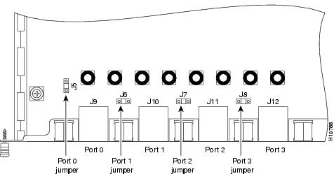
Setting the Receive Shield Jumpers
Jumpers on the quad E1/PRI card configure the 75-ohm unbalanced ports so the receive shield is connected to ground. You can remove these jumpers to disconnect the receive shield from ground (see ).
Figure 3 Receive Shield Jumpers for 75-ohm Unbalanced Ports
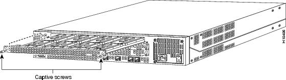
Removing a Feature Card
To remove a feature card, refer to and take these steps:
Step 1

Step 2
Step 3


Step 4
Figure 4 Removing a Feature Card (Carrier Card Shown)
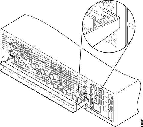
Step 5
.
Figure 5 Using the Feature Card Removal Tool
Step 6
Installing a Feature Card
To install a new feature card, refer to and take these steps:
Step 1
Step 2
Step 3
Step 4
Step 5
Step 6
Configuring Software
After you install or replace the feature card, configure the software as described in the following sections.
How to Find Command Options
This section explains how to display options for a command. To display options for a command, enter a ? at the configuration prompt, or after entering part of a command followed by a space. The configuration parser displays options available with the command. For example, if you were in global configuration mode, typed the command arap, and wanted to see all the keywords and arguments for that command, you would type arap ?.
shows examples of this function:
If you need further assistance, see the last section "Cisco Connection Online," page 30.
Configuring ISDN PRI
Configure the access server interfaces for ISDN PRI lines.
To verify you have configured the interfaces correctly:
•
5300# show controller t1 0T1 0 is up.No alarms detected.Framing is ESF, Line Code is B8ZS, Clock Source is Line Primary.Version info of slot 2: HW: 2, Firmware: 14, NEAT PLD: 13, NR Bus PLD: 19Data in current interval (476 seconds elapsed):0 Line Code Violations, 0 Path Code Violations0 Slip Secs, 0 Fr Loss Secs, 0 Line Err Secs, 0 Degraded Mins0 Errored Secs, 0 Bursty Err Secs, 0 Severely Err Secs, 0 Unavail SecsTotal Data (last 24 hours)0 Line Code Violations, 0 Path Code Violations,0 Slip Secs, 0 Fr Loss Secs, 0 Line Err Secs, 0 Degraded Mins,0 Errored Secs, 0 Bursty Err Secs, 0 Severely Err Secs, 0 Unavail SecsNote the following:
•
•
•
5300# show isdn statusThe current ISDN Switchtype = primary-5essISDN Serial0:23 interfaceLayer 1 Status:ACTIVELayer 2 Status:TEI = 0, State = MULTIPLE_FRAME_ESTABLISHEDLayer 3 Status:No Active Layer 3 Call(s)Activated dsl 0 CCBs = 0Total Allocated ISDN CCBs = 0ISDN Serial1:23 interfaceLayer 1 Status:ACTIVELayer 2 Status:TEI = 0, State = TEI_ASSIGNEDLayer 3 Status:No Active Layer 3 Call(s)Activated dsl 0 CCBs = 0Total Allocated ISDN CCBs = 0Note the following information for Serial 0:23 (the first half of the messages):
•
•
•
The second half of the messages display information for Serial 1:23.
Tips
If you are having trouble:
•
•
Configuring Channelized T1 or E1
Configure the access server for channelized T1 or E1 lines. This section includes information on configuring channelized T1 lines to support modem pooling.
To verify your controller is up and running and no alarms have been reported:
•
5300# show controller t1 0T1 0 is up.No alarms detected.Framing is ESF, Line Code is B8ZS, Clock Source is Line Primary.Version info of slot 2: HW: 2, Firmware: 14, NEAT PLD: 13, NR Bus PLD: 19Data in current interval (476 seconds elapsed):0 Line Code Violations, 0 Path Code Violations0 Slip Secs, 0 Fr Loss Secs, 0 Line Err Secs, 0 Degraded Mins0 Errored Secs, 0 Bursty Err Secs, 0 Severely Err Secs, 0 Unavail SecsTotal Data (last 24 hours)0 Line Code Violations, 0 Path Code Violations,0 Slip Secs, 0 Fr Loss Secs, 0 Line Err Secs, 0 Degraded Mins,0 Errored Secs, 0 Bursty Err Secs, 0 Severely Err Secs, 0 Unavail SecsNote the following:
•
•
If you are having trouble:
•
Configuring the D Channels for Modem Signaling
Configure the ISDN D channels, which carry the control and signaling information for ISDN calls, for each ISDN PRI line.
Table 8 Configuring the D Channels for Modem Signaling
5300> enable
Password: <password>
5300#
Enter enable mode.
Enter the password.
You have entered enable mode when the prompt changes to 5300#.
5300# config term
Enter configuration commands, one per line. End
with CNTL/Z.
5300(config)#
Enter global configuration mode. You have entered global configuration mode when the prompt changes to 5300(config)#.
5300(config)# interface serial [0:15 | 0:23]
5300(config-if)#
Enter serial interface configuration mode. After you have configured the controller, a corresponding D channel serial interface is created instantly. For example, serial interface 0:23 is the D channel for controller 0. You must configure each serial interface to receive incoming and send outgoing modem signaling.
5300(config-if)# ip address 172.16.253.254 255.255.255.0
Assign an IP address and subnet mask to the interface.
5300(config-if)# isdn incoming-voice modem
Configure all incoming voice calls to go to the modems.
5300(config-if)# dialer-group 1
Assign the serial interface to dialer group 1. The dialer group number is used with the dialer-list command to determine which packets will be meet the criteria specified by the dialer-list command and activate the ISDN connection.
5300(config-if)# encapsulation ppp
Changes the default to encapsulation ppp so you can enter ppp commands.
5300(config-if)# ppp multilink
Enable PPP1 multilink on the serial interface.
5300(config-if)# ppp authentication chap pap
Enable CHAP2 and PAP3 authentication on the serial interface.
5300(config-if)# peer default ip address pool default
Support dial-in PC clients.
5300(config-if)# Ctrl-Z
5300#
%SYS-5-CONFIG_I: Configured from console by console
Return to enable mode.
This message is normal and does not indicate an error.
1 PPP = Point-to-Point Protocol.
2 CHAP = Challenge Handshake Authentication Protocol.
3 PAP = Password Authentication Protocol.
To verify your D-channel configuration:
•
5300# show interface 1:23Serial1:23 is up, line protocol is upHardware is DSX1Interface is unnumbered. Using address of FastEthernet0 (15.0.0.60)MTU 1500 bytes, BW 64 Kbit, DLY 20000 usec, rely 255/255, load 1/255Encapsulation PPP, loopback not setLast input 00:00:00, output 00:00:00, output hang neverLast clearing of "show interface" counters neverQueueing strategy: fifoOutput queue 0/40, 0 drops; input queue 0/75, 0 drops5 minute input rate 0 bits/sec, 0 packets/sec5 minute output rate 0 bits/sec, 0 packets/sec54 packets input, 214 bytes, 0 no bufferReceived 0 broadcasts, 10 runts, 0 giants, 0 throttles10 input errors, 0 CRC, 0 frame, 0 overrun, 0 ignored, 0 abort53 packets output, 211 bytes, 0 underruns0 output errors, 0 collisions, 10 interface resets0 output buffer failures, 0 output buffers swapped out1 carrier transitionsTimeslot(s) Used:24, Transmitter delay is 0 flagsTips
If you are having trouble:
•
5300(config)# show interface serial 0:23Serial0:23 is up, line protocol is upHardware is DSX1Internet address is 61.0.0.2/8MTU 1500 bytes, BW 64 Kbit, DLY 20000 usec, rely 255/255, load 1/255Encapsulation PPP, loopback not setLast input 00:00:02, output 00:00:02, output hang neverLast clearing of "show interface" counters neverQueueing strategy: fifoOutput queue 0/40, 0 drops; input queue 0/75, 0 drops5 minute input rate 0 bits/sec, 0 packets/sec5 minute output rate 0 bits/sec, 0 packets/sec6442 packets input, 25855 bytes, 0 no bufferReceived 0 broadcasts, 8 runts, 0 giants, 0 throttles8 input errors, 0 CRC, 0 frame, 0 overrun, 0 ignored, 0 abort6439 packets output, 25875 bytes, 0 underruns0 output errors, 0 collisions, 8 interface resets0 output buffer failures, 0 output buffers swapped out1 carrier trnsitionsTimeslot(s) Used:24, Transmitter delay is 0 flags•
5300# debug dialerPRI0: Dialing cause: PRI0: ip PERMITPRI0: No dialer string defined. Dialing cannot occur..PRI0: Dialing cause: PRI0: ip PERMIT
•
5300# debug isdn q931%LINEPROTO-5-UPDOWN: Line protocol on Interface Serial1/0:22, changed state to upISDN Event: Call to 9086154535 dsl 3 at 64 Kb/sTX -> SETUP dsl = 3 pd = 8 callref = 0x188CBearer Capability i = 0x8890Channel ID i = 0xE1808397Called Party Number i = 0xA1, '95163287448'RX <- RELEASE_COMP dsl = 3 pd = 8 callref = 0x988CCause i = 0x83E020 - Mandatory IE missingISDN PRI 3: entering process_rxstate, CALL_CLEAREDISDN PRI 3: received message 1FISDN Event: Hangup call to call id 0xCE2 on dsl 2
Table 10 Debug ISDN Messages
TX ->
Indicates this message is being transmitted from the local router (user side) to the network side of the ISDN interface.
RX <-
Indicates this message is being received by the user side of the ISDN interface from the network side.
SETUP
Indicates the SETUP message has been sent to initiate call establishment between peer network layers. The message can be sent from the local router or network.
pd
Indicates the protocol discriminator. The protocol discriminator distinguishes messages for call control over the user-network ISDN interface from other ITU-T11 -defined messages, including other Q.931 messages. The protocol discriminator is 8 for call control messages such as SETUP.
callref
Indicates the call reference number in hexadecimal. The field value indicates the number of calls made from the router (outgoing calls) or the network (incoming calls). Note that the originator of the SETUP message sets the high-order bit of the call reference number to 0.
The destination of the connection sets the high-order bit to 1 in subsequent call control messages, such as the CONNECT message. For example, callref = 0x04 in the request becomes callref = 0x84 in the response.
Bearer Capability
Indicates the requested bearer service to be provided by the network.
i=
Indicates the Information Element Identifier. The value depends on the field it is associated with. Refer to the ITU-T Q.931 specification for details about the possible values associated with each field for which this identifier is relevant.
Channel ID
Indicates the Channel Identifier. The value 83 indicates any channel, 89 indicates the B1 channel, and 8A indicates the B2 channel. For more information about the Channel Identifier, refer to ITU-T Recommendation Q.931.
Called Party Number
Identifies the called party. This field is only present in outgoing SETUP messages. It can be replaced by the Keypad facility field. This field uses the IA5 character set.
RELEASE
Indicates that the sending equipment will release the channel and call reference. The recipient of this message should prepare to release the call reference and channel.
RELEASE_COMP
Indicates that the sending equipment has received a RELEASE message and has now released the call reference and channel.
1 ITU-T1 = International Telecommunication Union Telecommunication Standardization Sector.
Configuring R2 Signaling
R2 signaling is an international signaling standard that is common to channelized E1 networks. You can configure a channelized E1 interface to support different types of R2 signaling, which is used in older analog telephone networks.
Table 11 Configuring R2 Signaling
5300> enable
Password: <password>
5300#
Enter enable mode.
Enter the password.
You have entered enable mode when the prompt changes to 5300#.
5300# configure terminal
Enter configuration commands, one per line. End
with CNTL/Z.
5300(config)#
Enter global configuration mode. You have entered global configuration mode when the prompt changes to 5300(config)#.
5300(config)# controller e1 [0 | 1 | 2 | 3]
5300(config-controller)#
Enter controller configuration mode to configure your E1 controller port. The E1 controller ports are labeled 0-3 on the quad E1/PRI cards.
5300 (config-controller)# framing crc4
[or]
5300 (config-controller)# framing no-crc4
Configures framing to E1 with CRC1 .
Configures framing to E1 only.5300 (config-controller)# linecode ami
[or]
5300 (config-controller)# linecode hdb3
Configures line code to AMI2 encoding.
Configures line code to HDB3 encoding.5300 (config-controller)# clock source internal
[or]
5300 (config-controller)# clock source line primary
[or]
5300 (config-controller)# clock source line secondary
Configures the clock source to the internal clock.
Configures the clock source to the primary recovered clock.
Configures the clock source to the secondary recovered clock.
5300(config-controller)# cas-group 1 timeslots 1-30 type r2-analog r2-digital ani
Configure the timeslots that belong to each E1 circuit for R2 signaling. Sets R2 signaling to R2 ITU Q411, the tone signal to R2 Compelled Register Signaling, and the ANI addr info provisioned option.
R2 line signaling options include r2-analog, r2-digital, and r2-pulse.
Tone signaling options include dtmf (default), r2-compelled, r2-non-compelled, and r2-semi-compelled.
You can also set ani (ANI addr info provisioned) for any of the above options.
5300(config-controller-cas)# cas-custom 1
Enter the channel number to customize.
5300(config-ctrl-cas)# country country use-default
Use defaults for the specified country. Note: To view the parameters for the country (if the country defaults are the same as ITU defaults), enter write term.
5300(config-ctrl-cas)# answer-signal group-b 6
[or]5300(config-ctrl-cas)# default answer-signal group-b 6
[or]
5300(config-ctrl-cas)# no answer-signal group-b 6
controller E1 0
clock source line primary
cas-group 0 timeslots 1-15,17-31 type r2-analog
r2-compelled
cas-custom 0
country singapore use-defaults
category 2 <--- default category for singapore
answer-signal group-b 6 <--- default bxfree
for singapore5300(config-ctrl-cas)# exit
Sets the cas custom command answer-signal to group-b to 6.
Cas custom commands include caller-digits, category, country, unused-abcd, invert-abcd, metering, ka, kd, dnis-digits, answer-signal, and nc-congestion.
Sets answer-signal group-b to the default ITU value.
Resets answer-signal group-b 6 to the default value.Note: The parameters you do not set are automatically set to the ITU default by the Cisco AS5300.
After you configure a country with default settings, the Cisco AS5300 displays a write term, similar to the one displayed here.
Exits the cas-custom mode.5300(config-if)# Ctrl-Z
5300#
%SYS-5-CONFIG_I: Configured from console by console
Return to enable mode.
This message is normal and does not indicate an error.
1 CRC = Cyclic Redundancy Check.
2 AMI = Alternate Mark Inversion.
To verify your R2 signaling configuration:
•
5300# show controller e1 0E1 0 is up.Applique type is Channelized E1 - balancedNo alarms detected.Version info of Slot 0: HW: 2, Firmware: 4, PLD Rev: 2Manufacture Cookie is not programmed.Framing is CRC4, Line Code is HDB3, Clock Source is Line Primary.Data in current interval (785 seconds elapsed):0 Line Code Violations, 0 Path Code Violations0 Slip Secs, 0 Fr Loss Secs, 0 Line Err Secs, 0 Degraded Mins0 Errored Secs, 0 Bursty Err Secs, 0 Severely Err Secs, 0 Unavail SecsTotal Data (last 13 15 minute intervals):0 Line Code Violations, 0 Path Code Violations,0 Slip Secs, 12 Fr Loss Secs, 0 Line Err Secs, 0 Degraded Mins,0 Errored Secs, 0 Bursty Err Secs, 0 Severely Err Secs, 12 Unavail Secs•
5300# show modem csm 1/0MODEM_INFO: slot 1, port 0, unit 0, tone r2-compelled, modem_mask=0x0000, modem_port_offset=0tty_hwidb=0x60E63E4C, modem_tty=0x60C16F04, oobp_info=0x00000000, modem_pool=0x60BC60CCmodem_status(0x0002): VDEV_STATUS_ACTIVE_CALL.csm_state(0x0205)=CSM_IC5_CONNECTED, csm_event_proc=0x600CFF70, current call thru CAS lineinvalid_event_count=0, wdt_timeout_count=0wdt_timestamp_started is not activatedwait_for_dialing:False, wait_for_bchan:Falsepri_chnl=TDM_PRI_STREAM(s0, u3, c7), modem_chnl=TDM_MODEM_STREAM(s1, c0)dchan_idb_start_index=0, dchan_idb_index=0, call_id=0x0239, bchan_num=6csm_event=CSM_EVENT_DSX0_CONNECTED, cause=0x0000ring_no_answer=0, ic_failure=0, ic_complete=3dial_failure=0, oc_failure=0, oc_complete=0oc_busy=0, oc_no_dial_tone=0, oc_dial_timeout=0remote_link_disc=2, stat_busyout=2, stat_modem_reset=0oobp_failure=0call_duration_started=00:04:56, call_duration_ended=00:00:00, total_call_duration=00:01:43The calling party phone number =The called party phone number = 9993003total_free_rbs_timeslot = 0, total_busy_rbs_timeslot = 0, total_dynamic_busy_rbs_timeslot = 0, total_static_busy_rbs_timeslot = 0, min_free_modem_threshold = 0Tips
If you are having trouble, enable the modem management Call Switching Module (CSM) debug mode using the following command.
•
This is the output of debug modem csm for an incoming call:
5300# debug modem csm 1/0*May 15 04:05:46.675: VDEV_ALLOCATE: slot 2 and port 39 is allocated.*May 15 04:05:46.675: CSM_RX_CAS_EVENT_FROM_NEAT:(04BF): EVENT_CALL_DIAL_IN at slot 2 and port 39*May 15 04:05:46.675: CSM_PROC_IDLE: CSM_EVENT_DSX0_CALL at slot 2, port 39*May 15 04:05:46.675: Mica Modem(2/39): Configure(0x0)*May 15 04:05:46.675: Mica Modem(2/39): Configure(0x3)*May 15 04:05:46.675: Mica Modem(2/39): Configure(0x6)*May 15 04:05:46.675: Mica Modem(2/39): Call Setup*May 15 04:05:46.891: Mica Modem(2/39): State Transition to Call Setup*May 15 04:05:46.891: Mica Modem(2/39): Went offhook*May 15 04:05:46.891: CSM_PROC_IC1_RING: CSM_EVENT_MODEM_OFFHOOK at slot 2, port 39...When the E1 controller comes up, you will see the following messages:
%CONTROLLER-3-UPDOWN: Controller E1 0, changed state to upIt also shows these messages for individual timeslots:%DSX0-5-RBSLINEUP: RBS of controller 1 timeslot 1 is up%DSX0-5-RBSLINEUP: RBS of controller 1 timeslot 2 is up%DSX0-5-RBSLINEUP: RBS of controller 1 timeslot 3 is up%DSX0-5-RBSLINEUP: RBS of controller 1 timeslot 4 is up%DSX0-5-RBSLINEUP: RBS of controller 1 timeslot 5 is up%DSX0-5-RBSLINEUP: RBS of controller 1 timeslot 6 is up%DSX0-5-RBSLINEUP: RBS of controller 1 timeslot 7 is up%DSX0-5-RBSLINEUP: RBS of controller 1 timeslot 8 is up...Saving Configuration Changes
To prevent loss of the access server configuration, save it to NVRAM.
Using the Bantam Jacks
If a T1 controller does not come up, or there is a large number of errors associated with a particular controller, you might be able to determine whether the problem is in the quad T1/PRI card or in an external T1 line by using the bantam jacks. A rotary switch at the front of the T1/PRI card selects which of the four T1 lines are to be monitored/inspected. The LED labeled MON indicates which T1 line is connected to the bantam jacks.
External test equipment, such as a bit error rate tester, can be used to inject data into the TX IN jack and receive data from the RX OUT jack with the remote location in loop back. This would be an invasive test that would disrupt connections on that T1 port. Another example is to use passive monitoring equipment that can listen on the TX MON and RX MON jacks during regular operation to detect T1 errors.
Connecting test equipment to the following Bantam jacks provides various functions:
•
•
•
•
•
•
Quad T1 PRI Card Port Pinouts
lists the quad T1 PRI card port pinouts. Use a straight-through RJ-45-to-RJ-45 cable to connect the T1 port to an RJ-45 jack.
Table 13 Quad T1 PRI Card Port (RJ-45) Pinouts
1
RX Tip
2
RX Ring
3
RX Shield
4
TX Tip
5
TX Ring
6
TX Shield
7
-
8
-
Quad E1 PRI Card Cable Assemblies and Pinouts
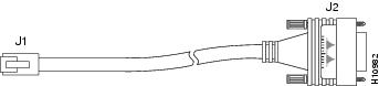
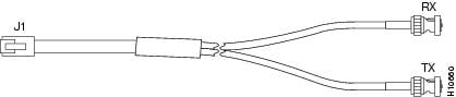
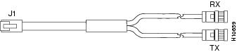
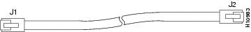
Eight serial cables are available from Cisco Systems for connecting the E1/PRI card ports:
Figure 6 RJ-45-to-DB-15 Interface Cable
Figure 7 RJ-45-to-BNC Interface Cable for 75-Ohm, Unbalanced Connections
Figure 8 RJ-45-to-Twinax Interface Cable for 120-Ohm, Balanced Connections
Figure 9 RJ-45-to-RJ-45 Interface Cable
Figure 10 RJ-45-to-Bare Wire Interface Cable
Cisco Connection Online
Cisco Connection Online (CCO) is Cisco Systems' primary, real-time support channel. Maintenance customers and partners can self-register on CCO to obtain additional information and services.
Available 24 hours a day, 7 days a week, CCO provides a wealth of standard and value-added services to Cisco's customers and business partners. CCO services include product information, product documentation, software updates, release notes, technical tips, the Bug Navigator, configuration notes, brochures, descriptions of service offerings, and download access to public and authorized files.
CCO serves a wide variety of users through two interfaces that are updated and enhanced simultaneously: a character-based version and a multimedia version that resides on the World Wide Web (WWW). The character-based CCO supports Zmodem, Kermit, Xmodem, FTP, and Internet e-mail, and it is excellent for quick access to information over lower bandwidths. The WWW version of CCO provides richly formatted documents with photographs, figures, graphics, and video, as well as hyperlinks to related information.
You can access CCO in the following ways:
•
•
•
•
•
For a copy of CCO's Frequently Asked Questions (FAQ), contact cco-help@cisco.com. For additional information, contact cco-team@cisco.com.
Note
78-4521-02