Feedback Feedback
|
Table Of Contents
Replacing the Power Supply in the Cisco AS5300 Series and Cisco AS5400 Series Routers
Preventing Electrostatic Discharge Damage
Removing and Installing the Cisco AS5300 Power Supply
Installing the New Power Supply
Removing and Installing the Cisco AS5350 Power Supply
Removing and Installing the Cisco AS5400 Power Supply
Verifying Status of the Redundant Power Supply
Configuring the Power Supply Alarm
Obtaining Technical Assistance
Replacing the Power Supply in the Cisco AS5300 Series and Cisco AS5400 Series Routers
Product Numbers: AS53-AC-PWR=, AS53-DC-PWR=, AS535-AC-PWR=, AS535-DC-PWR=, AS535-AC-RPS=, AS535-DC-RPS=, AS54-DC-RPS=, AS54-AC-RPS=
This document describes how to replace the internal AC or DC power supply in the Cisco AS5300 series and Cisco AS5400 series universal gateways, and includes the following sections:
•
Removing and Installing the Cisco AS5300 Power Supply
•
•
•
Safety Recommendations
Follow these guidelines to ensure general safety:
•
•
•
•
•
•
Safety Warnings
Safety warnings appear throughout this publication in procedures that, if performed incorrectly, may harm you. A warning symbol precedes each safety warning.
Safety with Electricity
Warning
Warning
Warning
Warning
Warning
Follow these guidelines when working on equipment powered by electricity:
•
•
–
–
•
•
•
•
–
–
–
–
Preventing Electrostatic Discharge Damage
Electrostatic discharge (ESD) can damage equipment and impair electrical circuitry. ESD occurs when electronic printed circuit cards are improperly handled, and can result in complete or intermittent failures. Always follow ESD prevention procedures when removing and replacing cards. Ensure that the chassis is electrically connected to earth ground. Wear an ESD-preventive wrist strap, ensuring that it makes good skin contact. Connect the clip to an unpainted surface of the chassis frame to safely channel unwanted ESD voltages to ground. To properly guard against ESD damage and shocks, the wrist strap and cord must operate effectively. If no wrist strap is available, ground yourself by touching the metal part of the chassis.
Caution
Related Documentation
This document is to be used with the following documents:
•
•
•
•
•
•
Required Tools and Equipment
To replace the power supply, you will need:
•
•
•
•
•
•
Removing and Installing the Cisco AS5300 Power Supply
The following sections describe how to remove and install the Cisco AS5300 power supply:
•
•
Note
Removing the Chassis Cover
This section describes how to access the internal components by removing the chassis cover.
Warning
Warning
Warning
Warning
To remove the chassis cover, follow these steps:
Step 1
Step 2
Step 3
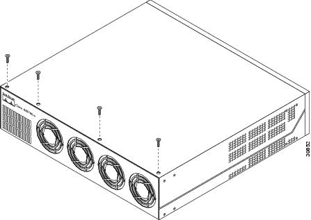
Step 4
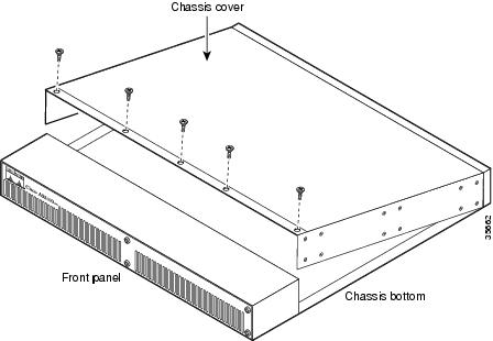
Figure 1 Removing the Chassis Cover Screws
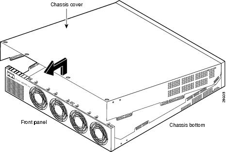
Step 5
Figure 2 Removing the Chassis Cover
Removing the Old Power Supply
This section describes how to remove the power supply. Note the following safety warnings before you remove the power supply:
Warning
Warning
Warning
Warning
Warning
To remove the power supply, follow these steps:
Step 1
Note
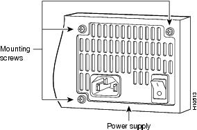
Step 2
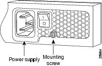
Figure 3 Removing the Power Supply Mounting Screws
Step 3
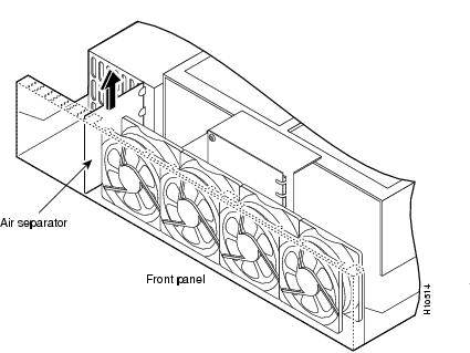
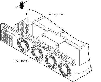
Step 4
Figure 4 Removing the Air Separator
Step 5
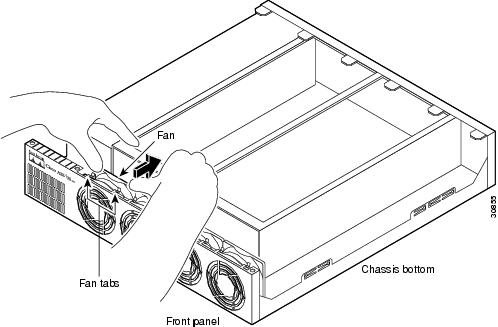
Figure 5 Pulling the Fan Away from the Tabs
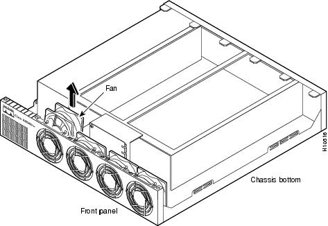
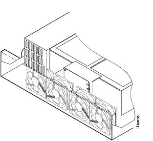
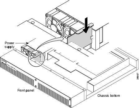
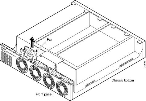
Step 6
Figure 6 Removing the Fan
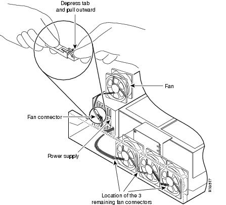
Step 7
Caution
Figure 7 Disconnecting the Fan Cable
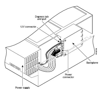
Step 8
Note
If you use an incorrect cable to connect a fan or the backplane, then you are unable to make one of the other connections.Step 9
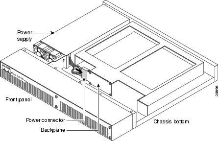
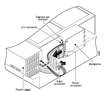
Figure 8 Disconnecting the Power Connectors from the Backplane
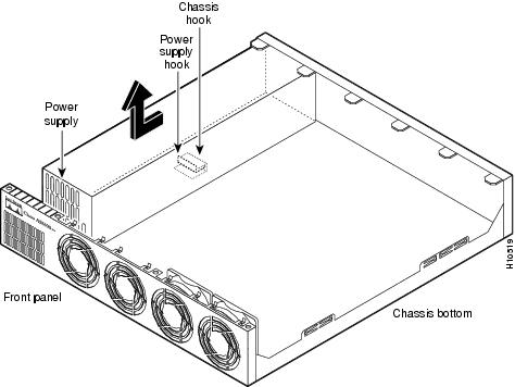
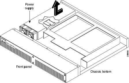
Step 10
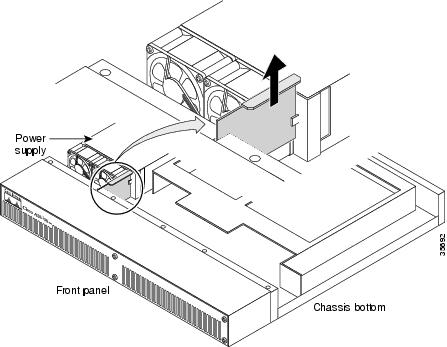
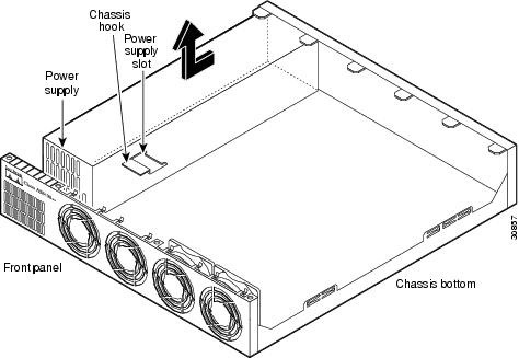
Figure 9 Removing the Power Supply from the Chassis
Warning
Installing the New Power Supply
To install the new power supply, follow these steps:
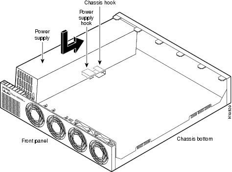
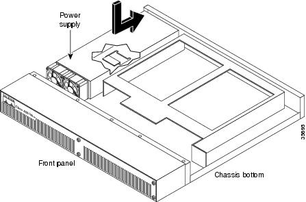
Step 1
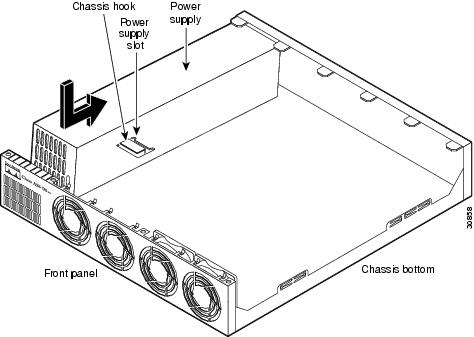
Figure 10 Inserting the Power Supply in the Chassis
Step 2
Note
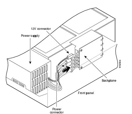
Caution
Figure 11 Reconnecting the Power Cables to the Backplane
Step 3
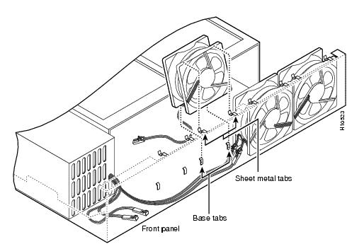
Note
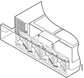
Figure 12 Routing the Fan Cables
Step 4
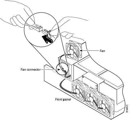
Step 5
Figure 13 Reconnecting the Fan Cables
Step 6
Figure 14 Correct Fan Cable Routing
Step 7
Figure 15 Replacing the Air Separator
Step 8
Figure 16 Replacing the Power Supply Mounting Screws
Step 9
Step 10
Replacing the Chassis Cover
To replace the chassis cover, follow these steps:
Step 1
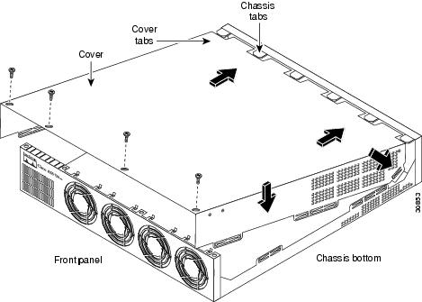
Step 2
Figure 19 Replacing the Chassis Cover
Step 3
•
•
•
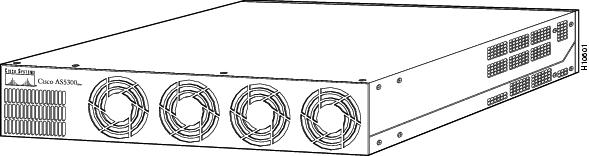
When the chassis cover is properly assembled, no tabs are visible. (See Figure 20.)
Figure 20 Cisco AS5300 Chassis
Step 4
Step 5
Step 6
Step 7
Warning
Step 8
The internal power supply fan should power on.
Removing and Installing the Cisco AS5350 Power Supply
The Cisco AS5350 universal gateway supports a single power supply or a redundant power supply. A redundant power supply has two power connections and provides higher reliability and load balancing. You can use the redundant power supply to:
•
•
•
Note
The following sections describe how to remove and install the Cisco AS5350 power supply:
•
Removing the Chassis Cover
You must open the universal gateway chassis to gain access to its interior components.
To open the chassis, follow these steps:
Step 1
Note
Note
Warning
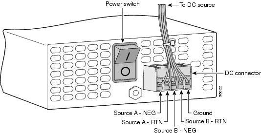
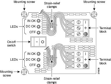
Figure 21 DC Power Supply Connections—Single Power Supply
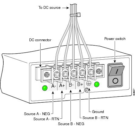
Figure 22 DC Power Supply Connections—Redundant Power Supply
a.
b.
c.
d.
Step 2
Step 3
Step 4
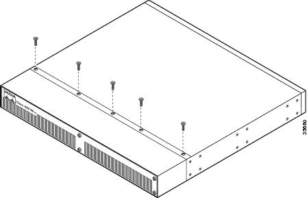
Figure 23 Removing the Chassis Cover Screws
Step 5
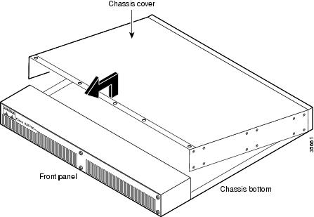
Figure 24 Removing the Chassis Cover
Step 6
Removing the Old Power Supply
This section describes how to remove the power supply. Note the following safety warnings before you remove the power supply:
Warning
Warning
Warning
Warning
Warning
To remove the power supply, follow this procedure:
Step 1
Step 2
Note
Figure 25 Removing the Power Supply Mounting Screws
Figure 26 Removing the Redundant Power Supply Mounting Screw
Step 3
Step 4
Figure 27 Removing the Air Separator
Note
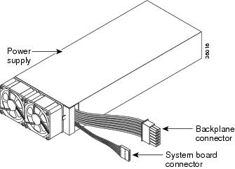
Figure 28 Power Supply Connectors
Step 5
Note
Figure 29 Disconnecting the Power Connectors from the Backplane
Step 6
Figure 30 Lifting the Power Supply Out of the Chassis
Installing the Power Supply
To install the power supply, follow this procedure:
Step 1
Figure 31 Inserting the Power Supply in the Chassis
Step 2
Note
Figure 32 Reconnecting the Power Cables to the Backplane
Step 3
Figure 33 Replacing the Air Separator
Step 4
Step 5
Replacing the Chassis Cover
To replace the chassis cover, follow this procedure:
Step 1
Step 2
Figure 34 Replacing the Chassis Cover
Step 3
•
•
•
When the chassis cover is properly assembled, no tabs are visible.
Step 4
Step 5
Step 6
Step 7
Step 8
Warning
Figure 37 Connecting DC Power Supply—Single Power Supply
Caution
Figure 38 Connecting DC Power Supply—Redundant Power Supply
Note
a.
Note
Note
b.
c.
d.
e.
Warning
Step 9
The internal power supply fan should power on.
Removing and Installing the Cisco AS5400 Power Supply
The Cisco AS5400 universal gateway has a redundant power supply. A redundant power supply has two power cords to provide higher reliability and load balancing. You can use the redundant power supply to:
•
•
•
The following sections describe how to remove and install the Cisco AS5400 power supply:
•
•
Removing the Chassis Cover
You must open the universal gateway chassis to gain access to its interior components.
To remove the chassis cover, follow these steps:
Step 1
Note
Step 2
Warning
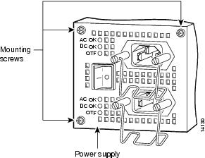
Figure 39 DC Power Supply Connections
a.
b.
c.
d.
Caution
Step 3
Step 4
Step 5
Figure 40 Removing the Chassis Cover Screws
Step 6
Figure 41 Removing the Chassis Cover
Step 7
Removing the Power Supply
This section describes how to remove the power supply. Note the following safety warnings before you remove the power supply:
Warning
Warning
Warning
Warning
Warning
To remove the power supply, follow these steps:
Step 1
Step 2
Note
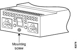
Figure 42 Removing the Power Supply Mounting Screws
Step 3
Step 4
Figure 43 Removing the Air Separator
Step 5
Figure 44 Pulling the Fan Away from the Tabs
Step 6
Figure 45 Removing the Fan
Step 7
Caution
Figure 46 Disconnecting the Fan Cable
Step 8
Step 9
Note
These cables are color-coded. If you use an incorrect cable to connect a fan or the backplane, then you are unable to make one of the other connections. To help with reconnecting the cables, write down which colored cable goes to each fan.Step 10
Figure 47 Disconnecting the Power Connectors from the Backplane
Step 11
Step 12
Figure 48 Lifting the Power Supply Out of the Chassis
Installing the Power Supply
To install the power supply, follow these steps:
Step 1
Figure 49 Inserting the Power Supply in the Chassis
Step 2
Note
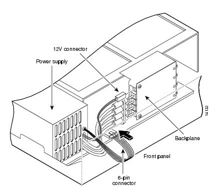
Figure 50 Connecting the 6-Pin Connector to the Motherboard
Step 3
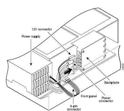
Figure 51 Reconnecting the Power Cables to the Backplane
Step 4
Note
Caution
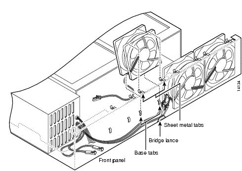
Figure 52 Routing the Fan Cables
Step 5
Note
Step 6
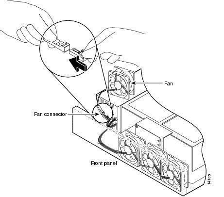
Figure 53 Reconnecting the Fan Cables
Step 7
Note
Figure 54 Correct Fan Cable Routing
Step 8
Figure 55 Replacing the Air Separator
Step 9
Figure 56 Replacing the Redundant Power Supply Mounting Screws
Step 10
Replacing the Chassis Cover
To replace the chassis cover, follow these steps:
Step 1
Step 2
Figure 57 Replacing the Chassis Cover
Step 3
•
•
•
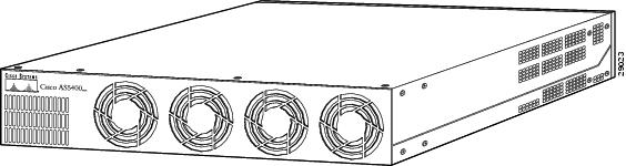
When the chassis cover is properly assembled, no tabs are visible, as shown in Figure 58.
Figure 58 Cisco AS5400 Chassis
Step 4
Step 5
Step 6
Step 7
Warning
Figure 59 DC Power Supply Connections
Caution
a.
b.
c.
d.
Warning
Note
Step 8
The internal power supply fan should power on. If you are using a redundant power supply, the six green LEDs on the front of the power supply should light. If one LED is not lit, consult the appropriate redundant power supply software message to determine where the problem is located.
Verifying Status of the Redundant Power Supply
To display the current status of the Redundant Power Supply unit, enter the show environment command.
Router# show environmentPower Supply:Redundant Power System is present.RPS Input Voltage status: normalRPS Output Voltage status: normalRPS Fan status: normalRPS Thermal status: normalRPS OverVoltage status: normalBoard Temperature:normalRouter#Configuring the Power Supply Alarm
You can configure the Cisco IOS software to poll every second to detect the failure of the redundant power supply. By default, the facility alarm is off. To begin monitoring the redundant power supply, enter the facility-alarm detect command. To disable the alarm, enter the no version of the command.
To configure alarm support for the redundant power supply, follow these steps:
Verify Alarm Configuration
To verify the status of the alarm configuration, enter the show facility-alarm command:
Router# show facility-alarmDevice State------ -----FastEthernet0/0 UPModem Card 4 UPFacility Alarm is ON
Note
Obtaining Documentation
These sections explain how to obtain documentation from Cisco Systems.
World Wide Web
You can access the most current Cisco documentation on the World Wide Web at this URL:
Translated documentation is available at this URL:
http://www.cisco.com/public/countries_languages.shtml
Documentation CD-ROM
Cisco documentation and additional literature are available in a Cisco Documentation CD-ROM package, which is shipped with your product. The Documentation CD-ROM is updated monthly and may be more current than printed documentation. The CD-ROM package is available as a single unit or through an annual subscription.
Ordering Documentation
You can order Cisco documentation in these ways:
•
http://www.cisco.com/en/US/partner/ordering/index.shtml
•
http://www.cisco.com/go/subscription
•
Documentation Feedback
You can submit comments electronically on Cisco.com. In the Cisco Documentation home page, click the Fax or Email option in the "Leave Feedback" section at the bottom of the page.
You can e-mail your comments to bug-doc@cisco.com.
You can submit your comments by mail by using the response card behind the front cover of your document or by writing to the following address:
Cisco Systems
Attn: Document Resource Connection
170 West Tasman Drive
San Jose, CA 95134-9883We appreciate your comments.
Obtaining Technical Assistance
Cisco provides Cisco.com as a starting point for all technical assistance. Customers and partners can obtain online documentation, troubleshooting tips, and sample configurations from online tools by using the Cisco Technical Assistance Center (TAC) Web Site. Cisco.com registered users have complete access to the technical support resources on the Cisco TAC Web Site.
Cisco.com
Cisco.com is the foundation of a suite of interactive, networked services that provides immediate, open access to Cisco information, networking solutions, services, programs, and resources at any time, from anywhere in the world.
Cisco.com is a highly integrated Internet application and a powerful, easy-to-use tool that provides a broad range of features and services to help you with these tasks:
•
•
•
•
•
If you want to obtain customized information and service, you can self-register on Cisco.com. To access Cisco.com, go to this URL:
Technical Assistance Center
The Cisco Technical Assistance Center (TAC) is available to all customers who need technical assistance with a Cisco product, technology, or solution. Two levels of support are available: the Cisco TAC Web Site and the Cisco TAC Escalation Center.
Cisco TAC inquiries are categorized according to the urgency of the issue:
•
•
•
•
The Cisco TAC resource that you choose is based on the priority of the problem and the conditions of service contracts, when applicable.
Cisco TAC Web Site
You can use the Cisco TAC Web Site to resolve P3 and P4 issues yourself, saving both cost and time. The site provides around-the-clock access to online tools, knowledge bases, and software. To access the Cisco TAC Web Site, go to this URL:
All customers, partners, and resellers who have a valid Cisco service contract have complete access to the technical support resources on the Cisco TAC Web Site. The Cisco TAC Web Site requires a Cisco.com login ID and password. If you have a valid service contract but do not have a login ID or password, go to this URL to register:
http://www.cisco.com/register/
If you are a Cisco.com registered user, and you cannot resolve your technical issues by using the Cisco TAC Web Site, you can open a case online by using the TAC Case Open tool at this URL:
http://www.cisco.com/tac/caseopen
If you have Internet access, we recommend that you open P3 and P4 cases through the Cisco TAC Web Site.
Cisco TAC Escalation Center
The Cisco TAC Escalation Center addresses priority level 1 or priority level 2 issues. These classifications are assigned when severe network degradation significantly impacts business operations. When you contact the TAC Escalation Center with a P1 or P2 problem, a Cisco TAC engineer automatically opens a case.
To obtain a directory of toll-free Cisco TAC telephone numbers for your country, go to this URL:
http://www.cisco.com/warp/public/687/Directory/DirTAC.shtml
Before calling, please check with your network operations center to determine the level of Cisco support services to which your company is entitled: for example, SMARTnet, SMARTnet Onsite, or Network Supported Accounts (NSA). When you call the center, please have available your service agreement number and your product serial number

.