Feedback
Table Of Contents
Cisco 4000 Series—Making Single-Mode FDDI Network Connections
FIP—Making Single-Mode FDDI Network Connections
Using FC-to-SC FDDI Adapters in the Cisco 4000 Series, Cisco 7000 Series, and Cisco 7500 Series Routers
Product Number: FC-SC-ADAPTER=
This publication contains instructions for making single-mode connections using FC-to-SC interface adapters (FC-SC-ADAPTERS=) in the Cisco 4000 series, Cisco 7000 series, and Cisco 7500 series routers.
FC-to-SC FDDI adapters allow newer versions of the Cisco 4000 series FDDI network processor module, and the FDDI Interface Processor (FIP), to be connected to existing FC-type optical fiber. All newer FDDI products are equipped with SC-type connectors and replace older versions of these products equipped with FC-type connectors; this FC-to-SC adapter prevents you from having to change the existing connectors on your FC-type fiber-optic cables. (You can also reverse the FC-to-SC adapter and use older FC-type, single-mode FDDI products with SC-type, single-mode optical fiber.)
This publication is for the FC-to-SC adapter installer, who should be familiar with electronic circuitry and wiring practices and have experience as an electronic or electromechanical technician.
This publication is to be used in conjunction with the following publications:
•
For Cisco 4000 series users—Cisco 4000 Series Public Network Certification publication. If you have a Cisco 4000-M, Cisco 4500-M, or Cisco 4700-M router, also use this publication with the Cisco 4000 Series Installation Guide publication that shipped with your router. If you have a Cisco 4000, refer to the Cisco 4000 Hardware Installation and Maintenance publication. If you have a Cisco 4500 or Cisco 4700, refer to the Cisco 4000 Series Hardware Installation and Maintenance publication.
•
Document Contents
This document contains the following sections, including step-by-step procedures for using an FC-to-SC adapter:
All users should review the following three sections before proceeding with the installation:
Cisco 4000 series (FDDI network processor module) users should refer to the following procedure:
•
Cisco 7000 series and Cisco 7500 series (FIP) users should refer to the following procedure:
•
The following section is for general reference for all users:
Note
Safety Recommendations
Follow these guidelines to ensure general safety:
•
•
•
Warning
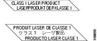
Invisible laser radiation may be emitted from the aperture ports of the single-mode FDDI card when no cable is connected. Avoid exposure and do not stare into open apertures.
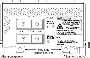
Following is an example of the warning label that appears on the product:
Figure 1 Warning Label on the Cisco 4000 series
Figure 2 Warning Label on the FIP
Note
•
Safety with Electricity
Warning
Before working on equipment that is connected to power lines, remove jewelry (including rings, necklaces, and watches). Metal objects will heat up when connected to power and ground. This can cause serious burns or even result in welding to the terminals.
Follow these guidelines when working on equipment powered by electricity:
•
•
•
•
•
•
•
•
•
•
•
Tools and Equipment Required
No additional tools or equipment are required to replace FC-to-SC connector adapters.
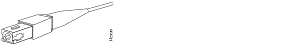
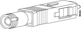
Older versions of the single-mode Cisco 4000 series network processor module and Cisco 7000 series and Cisco 7500 series FIP use simplex FC-type connectors (see ) for the transmit and receive ports. Newer versions of these products use simplex SC-type connectors. (See .) The connector accepts standard 8.7 to 10/125-micron single-mode fiber-optic cable. The single-mode interface supports connections at distances up to 6 miles (10 kilometers).
Figure 3 Older, FC-type Single-Mode FDDI Network Interface Connector
Figure 4 Newer, SC-type Single-Mode FDDI Network Interface Connector
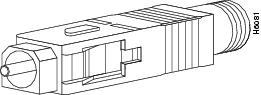
The FC-to-SC adapter (FC-SC-ADAPTER=) allows the newer, SC-type connector single-mode FDDI products to be used with cables installed for the earlier, FC-type connector versions. (See and .)
Figure 5 Single-Mode FDDI Network Interface FC-to-SC Adapter, FC End
Figure 6 Single-Mode FDDI Network Interface FC-to-SC Adapter, SC End
Cisco 4000 Series—Making Single-Mode FDDI Network Connections
Take the following steps to connect a single-mode FDDI module using the FC-to-SC FDDI adapter:
CautionFailure to observe these guidelines will prevent the FDDI interface from initializing correctly.
Warning
Invisible laser radiation may be emitted from the aperture ports of the single-mode FDDI card when no cable is connected. Avoid exposure and do not stare into open apertures.
Step 1
Step 2
Figure 7 Dual Attachment Single-Mode FDDI Network Processor Module with SC-type Connectors—End View
Step 3
Step 4
Step 5
This completes the FC-to-SC adapter single-mode FDDI network connections procedure. If you assistance, refer to the section "Cisco Connection Online."
FIP—Making Single-Mode FDDI Network Connections
Take the following steps to connect a single-mode FIP using the FC-to-SC FDDI adapter:
CautionFailure to observe these guidelines will prevent the FDDI interface from initializing correctly.
Warning
Invisible laser radiation may be emitted from the aperture ports of the single-mode FDDI card when no cable is connected. Avoid exposure and do not stare into open apertures.
Step 1
Note
Step 2
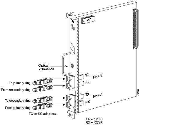
Figure 8 CX-FIP-SS with Four FC-type Connectors—Vertical FIP View
Step 3
Step 4
Step 5
This completes the FC-to-SC adapter single-mode FDDI network connections procedure for the FIP. If you assistance, refer to the section "Cisco Connection Online" on page 9.
Translated Safety Warnings
Warning
Invisible laser radiation may be emitted from the aperture ports of the single-mode FDDI card when no cable is connected. Avoid exposure and do not stare into open apertures.
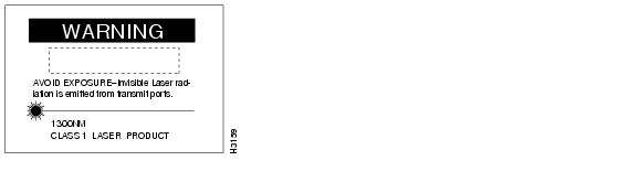
Following is an example of the laser warning label that appears on the Cisco 4000 series FDDI processor module:
Following is an example of the laser warning labels that appear on the FIP:
Waarschuwing Wanneer geen kabel aangesloten is, kan er onzichtbare laserstraling geëmitteerd worden uit de apertuurpoorten van de enkelvoudige-modus FDDI-kaart ("Fiber Distributed Data Interface" = "Interface van door glasvezels gedistribueerde gegevens"). Vermijd blootstelling en staar niet in de open aperturen.
Varoitus Yksitoimintoisen FDDI-kortin avoimista porteista saattaa vapautua näkymättömiä lasersäteitä kaapelin ollessa irrotettuna. Vältä säteilyä ja avoimiin aukkoihin katsomista.
Attention Des rayons laser invisibles peuvent s'échapper des ouvertures prévues pour la carte d'interface des données distribuées par fibres optiques monomode (Fiber Distributed Data Interface ou FDDI) quand un câble n'est pas connecté. Eviter toute exposition et ne pas approcher les yeux des ouvertures.
Warnung Wenn kein Kabel angeschlossen ist, wird möglicherweise unsichtbare Laserstrahlung von den Steckanschlüssen der Monomode-FDDI-Karte (Glasfaserdatenübertragungs-Schnittstelle; Fiber Distributed Data Interface) ausgestrahlt. Schützen Sie sich vor Strahlung, und blicken Sie nicht direkt in offene Steckanschlüsse.
Avvertenza Radiazioni laser invisibili potrebbero essere emesse dalle porte di apertura della scheda FDDI (Fiber Distributed Data Interface - Interfaccia di dati distribuiti a fibre) a modo singolo quando il cavo non è stato collegato. Evitare l'esposizione a tali radiazioni e non fissare alcuna porta aperta.
Advarsel Usynlig laserstråling kan emitteres fra åpningsutgangene på FDDI-kort med kabel av monomodusfiber når de ikke er tilkoblet en ledning. Unngå utsettelse for stråling, og stirr ikke inn i åpne åpninger.
Aviso Radiação laser invisível poderá ser emitida através das portas de abertura da placa FDDI (Interface de Dados Distribuídos por Fibra Óptica) de modo simples, mesmo quando não houver nenhum cabo ligado. Evite exposição e não espreite por estas aberturas.
¡Atención! La tarjeta FDDI modo sencillo puede emitir radiaciones láser invisibles por los orificios de los puertos cuando no se haya conectado ningún cable. Evitar la exposición y no mirar fijamente los orificios abiertos.
Varning! Osynlig laserstrålning kan avges från portöppningarna för FDDI-kortet för enkelmodsfiber när ingen kabel är ansluten (FDDI: Fiber Distributed Data Interface = gränssnitt för dataöverföring med fiberoptik). Utsätt dig inte för denna strålning och titta inte in i öppningarna.
Warning
Class 1 laser product.
Waarschuwing Klasse-1 laser produkt.
Varoitus Luokan 1 lasertuote.
Attention Produit laser de classe 1.
Warnung Laserprodukt der Klasse 1.
Avvertenza Prodotto laser di Classe 1.
Advarsel Laserprodukt av klasse 1.
Aviso Produto laser de classe 1.
¡Atención! Producto láser Clase I.
Varning! Laserprodukt av klass 1.
Cisco Connection Online
Cisco Connection Online (CCO), formerly Cisco Information Online (CIO), is Cisco Systems' primary, real-time support channel. Maintenance customers and partners can self-register on CCO to obtain additional content and services.
Available 24 hours a day, 7 days a week, CCO provides a wealth of standard and value-added services to Cisco's customers and business partners. CCO services include product information, software updates, release notes, technical tips, the Bug Navigator, configuration notes, brochures, descriptions of service offerings, and download access to public and authorized files.
CCO serves a wide variety of users through two interfaces that are updated and enhanced simultaneously—a character-based version and a multimedia version that resides on the World Wide Web (WWW). The character-based CCO supports Zmodem, Kermit, Xmodem, FTP, and Internet e-mail, and is excellent for quick access to information over lower bandwidths. The WWW version of CCO provides richly formatted documents with photographs, figures, graphics, and video, as well as hyperlinks to related information.
You can access CCO in the following ways:
•
•
•
•
•
For a copy of CCO's Frequently Asked Questions (FAQ), contact cco-help@cisco.com. For additional information, contact cco-team@cisco.com.
Note
tac@cisco.com.To obtain general information about Cisco Systems, Cisco products, or upgrades, contact 800 553-6387, 408 526-7208, orcs-rep@cisco.com.
Doc. No. 78-3549-02
Customer Order Number: DOC-783549=