[an error occurred while processing this directive]

Cisco 3700 Series Multiservice Access Routers

Cisco 2691, 3725, and 3745 Modular Access Routers FIPS 140-2 Non-Proprietary Security Policy

Table Of Contents

Cisco 2691 and 3725 Modular Access Routers with AIM-VPN/EP II and Cisco 3745 Modular Access Router with AIM-VPN/HP II FIPS 140-2 Non-Proprietary Security Policy

Introduction

References

Terminology

Document Organization

The Cisco 2691, 3725 and 3745 Routers

The Cisco 2691, 3725 and 3745 Cryptographic Module

Module Interfaces

Roles and Services

Crypto Officer Services

User Services

Physical Security

Cryptographic Key Management

Key Zeroization:

Self-Tests

Self-tests performed by the IOS image:

Self-tests performed by the AIM-VPN/EP II and AIM-VPN/HP II(cryptographic accelerators):

Secure Operation of the Cisco 2691, 3725, and 3745 Routers

Initial Setup

System Initialization and Configuration

IPSec Requirements and Cryptographic Algorithms

Protocols

Remote Access

Related Documentation

Obtaining Documentation

Cisco.com

Ordering Documentation

Documentation Feedback

Obtaining Technical Assistance

Cisco Technical Support Website

Submitting a Service Request

Definitions of Service Request Severity

Obtaining Additional Publications and Information


Cisco 2691 and 3725 Modular Access Routers with AIM-VPN/EP II and Cisco 3745 Modular Access Router with AIM-VPN/HP II FIPS 140-2 Non-Proprietary Security Policy


Level 2 Validation
Version 1.3
April 21, 2004

Introduction

This is the non-proprietary Cryptographic Module Security Policy for the 2691 and 3725 Modular Access Routers with AIM-VPN/EPII and 3745 Modular Access Router with AIM-VPN/HPII. This security policy describes how the 2691, 3725 and 3745 routers (Hardware Version: 2691, 3725, 3745; AIM-VPN/EPII: Hardware Version 1.0, Board Version A0; AIM-VPN/HPII: Hardware Version 1.0, Board Version A0; Firmware Version: IOS 12.3(3d)) meet the security requirements of FIPS 140-2, and how to operate the routers in a secure FIPS 140-2 mode. This policy was prepared as part of the Level 2 FIPS 140-2 validation of these routers.

FIPS 140-2 (Federal Information Processing Standards Publication 140-2 - Security Requirements for Cryptographic Modules) details the U.S. Government requirements for cryptographic modules. More information about the FIPS 140-2 standard and validation program is available on the NIST website at http://csrc.nist.gov/cryptval/.

This document contains the following sections:

Introduction

The Cisco 2691, 3725 and 3745 Routers

Secure Operation of the Cisco 2691, 3725, and 3745 Routers

Related Documentation

Obtaining Documentation

Documentation Feedback

Obtaining Technical Assistance

Obtaining Additional Publications and Information

References

This document deals only with operations and capabilities of the 2691, 3725 and 3745 routers in the technical terms of a FIPS 140-2 cryptographic module security policy. More information is available on these routers, the entire 2600 Series and the entire 3700 Series from the following sources:

The Cisco Systems website contains information on the full line of products at www.cisco.com. The 2600 Series product descriptions can be found at:

http://www.cisco.com/en/US/products/hw/routers/ps259/index.html

The 3700 series product descriptions can be found at:

http://www.cisco.com/en/US/products/hw/routers/ps282/index.html

For answers to technical or sales related questions please refer to the contacts listed on the Cisco Systems website at www.cisco.com.

The NIST Validated Modules website (http://csrc.nist.gov/cryptval) contains contact information for answers to technical or sales-related questions for the module

Terminology

In this document, the Cisco 2691 and 3725 Modular Access Routers with AIM-VPN/EP II, and the Cisco 3745 Modular Access Router with AIM-VPN/HP II, are referred to as the routers, the modules, or the systems.

Document Organization

The Security Policy document is part of the FIPS 140-2 Submission Package. In addition to this document, the Submission Package contains:

Vendor Evidence document

Finite State Machine

Module Software Listing

Other supporting documentation as additional references

This document provides an overview of the 2691, 3725 and 3745 routers and explains the secure configuration and operation of the modules. This introduction section is followed by the section "The Cisco 2691, 3725 and 3745 Routers", which details the general features and functionality of the routers. The section "Secure Operation of the Cisco 2691, 3725, and 3745 Routers" specifically addresses the required configuration for the FIPS-mode of operation.

With the exception of this Non-Proprietary Security Policy, the FIPS 140-2 Validation Submission Documentation is Cisco-proprietary and is releasable only under appropriate non-disclosure agreements. For access to these documents, please contact Cisco Systems.

The Cisco 2691, 3725 and 3745 Routers

Branch office networking requirements are dramatically evolving, driven by web and e-commerce applications to enhance productivity and merging the voice and data infrastructure to reduce costs. The Cisco 2691, 3725 and 3745 routers offer versatility, integration, and security to branch offices. With over 100 Network Modules (NMs) and WAN Interface Cards (WICs), the modular architecture of the Cisco router easily allows interfaces to be upgraded to accommodate network expansion. The Cisco 2691, 3725 and 3745 provide a scalable, secure, manageable remote access server that meets FIPS 140-2 Level 2 requirements. This section describes the general features and functionality provided by the Cisco 2691, 3725 and 3745 routers.

The Cisco 2691, 3725 and 3745 Cryptographic Module

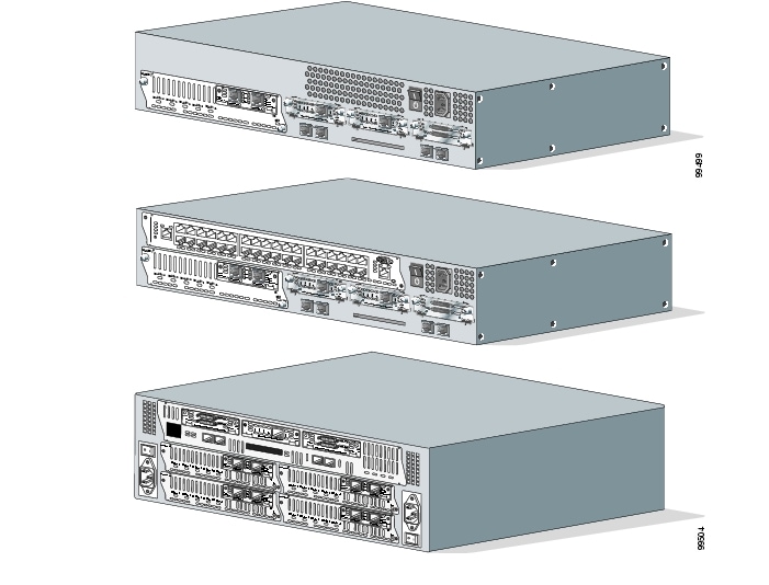
Figure 1 The Cisco 2691, 3725 and 3745 Routers

The 2691, 3725 and 3745 Routers are multi-chip standalone cryptographic modules. The cryptographic boundary is defined as encompassing the "top," "front," "left," "right," and "bottom" surfaces of the case; all portions of the "backplane" of the case which are not designed to accommodate a WIC or Network Module; and the inverse of the three-dimensional space within the case that would be occupied by an installed WIC or Network Module. The cryptographic boundary includes the connection apparatus between the WIC or Network Module and the motherboard/daughterboard that hosts the WIC or Network Module, but the boundary does not include the WIC or Network Module itself. In other words, the cryptographic boundary encompasses all hardware components within the case of the device except any installed modular WICs or Network Modules. All of the functionality discussed in this document is provided by components within this cryptographic boundary.

The 2691 and 3725 routers incorporate the AIM-VPN/EP II cryptographic accelerator card. The AIM-VPN/EP II is located inside the module chassis, and is installed directly on the motherboard. The 3745 router incorporates the AIM-VPN/HP II cryptographic accelerator card. The AIM-VPN/HP II is located inside the module chassis, and is installed directly on the motherboard.

Cisco IOS features such as tunneling, data encryption, and termination of Remote Access WANs via IPSec, Layer 2 Forwarding (L2F) and Layer 2 Tunneling Protocols (L2TP) make the Cisco 2600 Series and 3700 Series ideal platforms for building virtual private networks or outsourced dial solutions. The RISC-based processors of these routers provide the power needed for the dynamic requirements of the remote branch office, achieving wire speed Ethernet to Ethernet routing with up to 70 thousand packets per second (Kpps) throughput capacity for the 2691, 100 Kpps throughput capacity for the 3725, and 225 Kpps for the 3745.
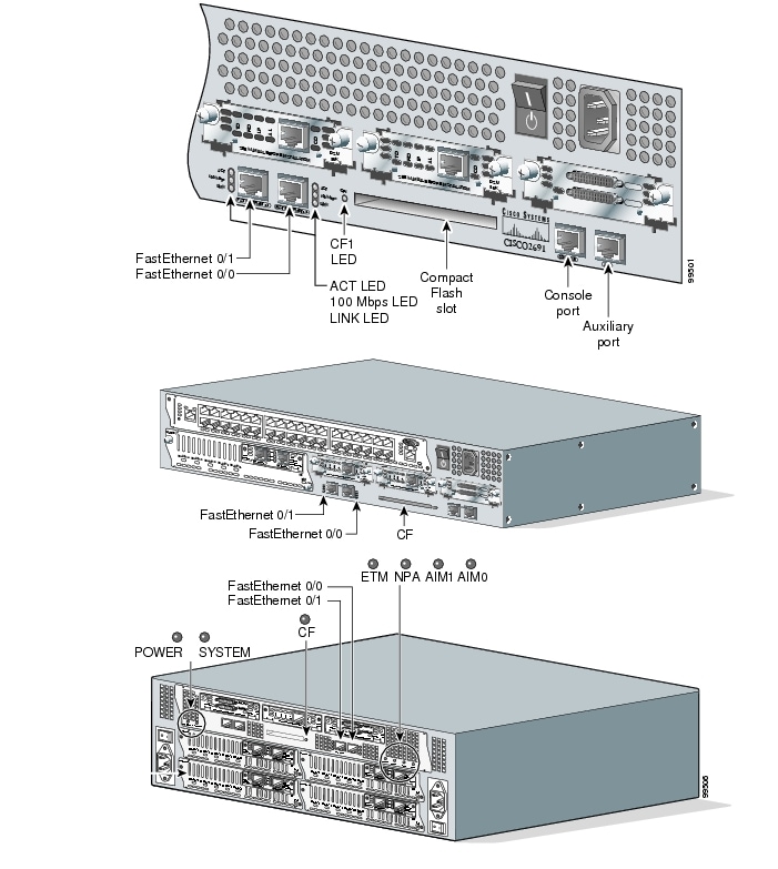
Module Interfaces

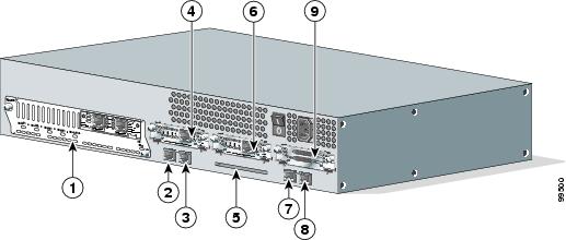
The interfaces for the router are located on the rear panel as shown in Figure 2, Figure 3, and Figure 4.

Figure 2 Cisco 2691 Physical Interfaces

1

Network Module

6

Interface Card Slot

2

FastEthernet 0/1

7

Console Port

3

FastEthernet 0/0

8

Auxiliary Port

4

Interface Card Slot

9

Interface Card Slot

5

Compact Flash Slot


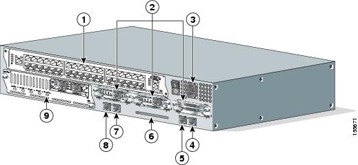
Figure 3 Cisco 3725 Physical Interfaces

1

Interface Card Slots

5

Console Port

2

Network Modules

6

Compact Flash Slot

3

Power Supply

7

FastEthernet 0/0

4

Auxiliary Port

8

FastEthernet 0/1


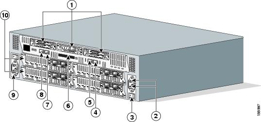
Figure 4 Cisco 3745 Physical Interfaces

1

Interface Card Slots

5

FastEthernet 0/1

2

Network Modules

6

Compact Flash Slot

3

Power Supply

7

Auxiliary Port

4

FastEthernet 0/0

8

Console Port


The Cisco 2691, 3725 and 3745 routers feature console and auxiliary ports, dual fixed LAN interfaces, one network module slot on the 2691, two network module slots on the 3725 and four on the 3745, three Cisco WAN interface card (WIC) slots, and a Compact Flash slot.

LAN support includes single and dual Ethernet options; 10/100 Mbps auto-sensing Ethernet; mixed Token-Ring and Ethernet; and single Token Ring chassis versions. WAN interface cards support a variety of serial, ISDN BRI, and integrated CSU/DSU options for primary and backup WAN connectivity, while available Network Modules support multi-service voice/data/fax integration, departmental dial concentration, and high-density serial options. The AIM slot supports integration of advanced services such as hardware-assisted data compression and encryption. All routers include an auxiliary port supporting 115Kbps Dial-On-Demand Routing, ideal for back-up WAN connectivity.

When a Network Module is inserted, it fits into an adapter called the Network Module expansion bus. The expansion bus interacts with the PCI bridge in the same way that the fixed LAN ports do; therefore, no critical security parameters pass through the Network Module (just as they don't pass through the LAN ports). Network modules do not perform any cryptographic functions.

WICs are similar to Network Modules in that they greatly increase the router's flexibility. A WIC is inserted into one of two slots, which are located above the fixed LAN ports. WICs interface directly with the processor. They do not interface with the cryptographic card; therefore no security parameters will pass through them. WICs cannot perform cryptographic functions; they only serve as a data input and data output physical interface.

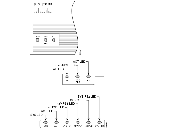
The physical interfaces include a power plug for the power supply and a power switch. The router has two Fast Ethernet (10/100 RJ-45) connectors for data transfers in and out. The module also has two other RJ-45 connectors on the back panel for a console terminal for local system access and an auxiliary port for remote system access or dial backup using a modem. The 10/100Base-T LAN ports have Link/Activity, 10/100Mbps, and half/full duplex LEDs. Figure 5 shows the LEDs located on the rear panel with descriptions detailed in Table 1, Table 2, and Table 3:

Figure 5 Cisco 2691, 3725, and 3745 Rear Panel LEDs

Table 1 Cisco 2691 Rear Panel LEDs and Descriptions 

LED
Indication
Description

LINK

On

An Ethernet link has been established

Off

No Ethernet link established

ACT

On

The interface is transmitting or receiving packets

Off

The interface is not transmitting or receiving packets

100 Mbps

On

The speed of the interface is 100 Mbps

Off

The speed of the interface is 10 Mbps or no link is established

CF1

On

The Flash device is being accessed in either READ or WRITE mode

Off

The Flash device is not being accessed


Table 2 Cisco 3725 Rear Panel LEDs and Descriptions 

LED
Indication
Description

CF

Solid or blinking green

Do not eject Compact Flash (CF); device is busy

Off

CF can be ejected; device is idle

FastEthernet 0/0 ACT
and
FastEthernet 0/1 ACT

Solid or blinking green

Interface receiving packets

Off

Interface not receiving packets

FastEthernet 0/0 LINK
and
FastEthernet 0/1 LINK

Solid green

An Ethernet link has been established

Off

No Ethernet link established

FastEthernet 0/0 100Mbps
and
FastEthernet 0/1 100Mbps

Solid green

The speed of the interface is 10 Mbps or no link is established

Off

The speed of the interface is 100 Mbps


Table 3 Cisco 3745 Rear Panel LEDs and Descriptions 

LED

Indication

Description

POWER

Solid green

Operating voltages on mainboard are within acceptable ranges

Off

Error condition is detected in the operating ranges

SYS

Solid green

Router operating normally

Blinking green

Router running ROM monitor; no errors detected

Amber

Router receiving power but malfunctioning

Off

Router not receiving power

CF

Solid or blinking green

Do not eject Compact Flash (CF); device is busy

Off

CF can be ejected; device is idle

FastEthernet 0/0 ACT
and
FastEthernet 0/1 ACT

Solid or blinking green

Interface receiving packets

Off

Interface not receiving packets

FastEthernet 0/0 LINK
and
FastEthernet 0/1 LINK

Solid green

An Ethernet link has been established

Off

No Ethernet link established

FastEthernet 0/0 100Mbps
and
FastEthernet 0/1 100Mbps

Solid green

The speed of the interface is 10 Mbps or no link is established

Off

The speed of the interface is 100 Mbps

ETM

Solid green

Enhanced timing module (ETM) present and enabled

Amber

ETM present with failure

Off

ETM not present

NPA

Not used

Reserved for future development

AIM0
and
AIM1

Solid green

Advanced Integration Module (AIM) present and enabled

Amber

AIM present with failure

Off

AIM not present


Figure 6 shows the front panel LEDs, which provide overall status of the router's operation. The front panel displays whether or not the router is booted, if the redundant power is (successfully) attached and operational, and overall activity/link status.

Table 4, Table 5, and Table 6 provide more detailed information conveyed by the LEDs on the front panel of the routers:

Figure 6 Cisco 2691, 3725, and 3745 Front Panel LEDs

Table 4 , Table 5, and Table 6 provide more detailed information conveyed by the LEDs on the front panels of the routers:

Table 4 Cisco 2691 Front Panel LEDs and Descriptions 

LED
Indication
Description

PWR

On

Power is supplied to the router


Off

The router is not powered on

SYS/RPS

Rapid blinking

System is booting


Slow blinking

System error


On

System OK

ACT

Off

No system activity


Blinking

System activity


Table 5 Cisco 3725 Front Panel LEDs and Descriptions 

LED
Indication
Description

PWR

Solid green

Router is receiving power

Off

Router is not receiving power

SYS/RPS

Solid green

System is operating normally

Rapid blinking

System is booting up or in ROM monitor mode

Blinking once per second

Redundant power system has failed

Off

Router is not receiving power

ACT

Blinking

System is actively transferring packets

Off

No packet transfers are occurring


Table 6 Cisco 3745 Front Panel LEDs and Descriptions 

LED
Indication
Description

SYS

Solid green

System is operating normally

Blinking green

Running ROM monitor with no errors detected

Amber

Router is receiving power but malfunctioning

Off

Router is not receiving power

ACT

Solid or blinking green

System is receiving interrupts, or is actively transferring packets

Off

No interrupts or packet transfers are occurring

SYS PS1
and
SYS PS2

Solid green

Power supply installed and operating normally

Amber

Power supply installed and powered off, or fault condition occurred

Off

Power supply not present, or failed

-48V PS1
and
-48V PS2

Solid green

-48V power module installed and operating normally

Amber

-48V power module installed and powered off, or fault condition occurred

Off

-48V power module not present, or failed


All of these physical interfaces are separated into the logical interfaces from FIPS 140-2 as described in Table 7:

Table 7 FIPS 140-2 Logical Interfaces 

Router Physical Interface
FIPS 140-2 Logical Interface

10/100BASE-TX LAN Port
WIC Interface
Network Module Interface
Console Port
Auxiliary Port
Compact Flash slot

Data Input Interface

10/100BASE-TX LAN Port
WIC Interface
Network Module Interface
Console Port
Auxiliary Port
Compact Flash slot

Data Output Interface

10/100BASE-TX LAN Port
WIC Interface
Network Module Interface
Power Switch
Console Port
Auxiliary Port

Control Input Interface

10/100BASE-TX LAN Port
WIC Interface
Network Module Interface
LAN Port LEDs
10/100BASE-TX LAN Port LEDs
Power LED
System LED
Activity LED
Console Port
Auxiliary Port

Status Output Interface

Power Plug

Power Interface


In addition to the built-in interfaces, the router also has over 100 network cards that can optionally be placed in an available slot. These networks cards have many embodiments, including multiple Ethernet, token ring, and modem cards to handle frame relay, ATM, and ISDN connections.

Roles and Services

Authentication is role-based. There are two main roles in the router that operators may assume: the Crypto Officer role and the User role. The administrator of the router assumes the Crypto Officer role in order to configure and maintain the router using Crypto Officer services, while the Users exercise only the basic User services. Both roles are authenticated by providing a valid username and password. The configuration of the encryption and decryption functionality is performed only by the Crypto Officer after authentication to the Crypto Officer role by providing a valid Crypto Officer username and password. Once the Crypto Officer has configured the encryption and decryption functionality, the User can use this functionality after authentication to the User role by providing a valid User username and password. The Crypto Officer can also use the encryption and decryption functionality after authentication to the Crypto Officer role. The module supports RADIUS and TACACS+ for authentication and they are used in the FIPS mode. A complete description of all the management and configuration capabilities of the Cisco Routers can be found in the Performing Basic System Management manuals and in the online help for the routers.

The User and Crypto Officer passwords and the RADIUS/TACACS+ shared secrets must each be at least 8 alphanumeric characters in length. See the "Secure Operation of the Cisco 2691, 3725, and 3745 Routers" section for more information. If only integers 0-9 are used without repetition for an 8 digit PIN, the probability of randomly guessing the correct sequence is 1 in 1,814,400. Including the rest of the alphanumeric characters drastically decreases the odds of guessing the correct sequence.

Crypto Officer Services

During initial configuration of the router, the Crypto Officer password (the "enable" password) is defined. A Crypto Officer may assign permission to access the Crypto Officer role to additional accounts, thereby creating additional Crypto Officers.

The Crypto Officer role is responsible for the configuration and maintenance of the router. The Crypto Officer services consist of the following:

Configure the router—define network interfaces and settings, create command aliases, set the protocols the router will support, enable interfaces and network services, set system date and time, and load authentication information.

Define Rules and Filters—create packet Filters that are applied to User data streams on each interface. Each Filter consists of a set of Rules, which define a set of packets to permit or deny based characteristics such as protocol ID, addresses, ports, TCP connection establishment, or packet direction.

Status Functions—view the router configuration, routing tables, active sessions, use Gets to view SNMP MIB II statistics, health, temperature, memory status, voltage, packet statistics, review accounting logs, and view physical interface status

Manage the router—log off users, shutdown or reload the router, manually back up router configurations, view complete configurations, manager user rights, and restore router configurations.

Set Encryption/Bypass—set up the configuration tables for IP tunneling. Set keys and algorithms to be used for each IP range or allow plaintext packets to be set from specified IP address.

Change Network Modules—insert and remove modules in the Network Module slot as described in the "Initial Setup" section of this document.

Change WAN Interface Cards—insert and remove WICs in the WAN interface slot as described in the "Initial Setup" section of this document.

User Services

A User enters the system by accessing the console port with a terminal program. The IOS prompts the User for their password. If the password is correct, the User is allowed entry to the IOS executive program. The services available to the User role consist of the following:

Status Functions—view state of interfaces, state of layer 2 protocols, version of IOS currently running

Network Functions—connect to other network devices through outgoing telnet, PPP, etc. and initiate diagnostic network services (i.e., ping, mtrace)

Terminal Functions—adjust the terminal session (e.g., lock the terminal, adjust flow control)

Directory Services—display directory of files kept in flash memory

Physical Security

The router is entirely encased by a thick steel chassis. The rear of the unit provides Network Module slots, 3 WIC slots, on-board LAN connectors, Console/Auxiliary connectors, Compact Flash slot, the power cable connection and a power switch. The top portion of the chassis may be removed to allow access to the motherboard, memory, and expansion slots.

Any NM or WIC slot, which is not populated with a NM or WIC, must be populated with an appropriate slot cover in order to operate in a FIPS compliant mode. The slot covers are included with each router, and additional covers may be ordered from Cisco. The same procedure mentioned below to apply tamper evidence labels for NMs and WICs must also be followed to apply tamper evidence labels for the slot covers.

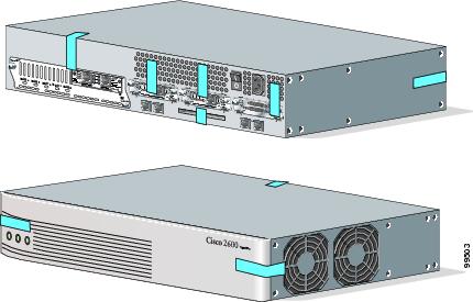
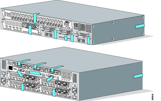
Once the router has been configured in to meet FIPS 140-2 Level 2 requirements, the router cannot be accessed without signs of tampering. To seal the system, apply serialized tamper-evidence labels as follows.

To apply tamper-evidence labels to the Cisco 2691:


Step 1 Clean the cover of any grease, dirt, or oil before applying the tamper evidence labels. Alcohol-based cleaning pads are recommended for this purpose. The temperature of the router should be above 10 C.

Step 2 Place the first label on the router as shown in Figure 7. The tamper evidence label should be placed so that the one half of the tamper evidence label covers the enclosure and the other half covers the right side of the router. Any attempt to remove the enclosure will leave tamper evidence.

Step 3 Place the second label on the router as shown in Figure 7. The tamper evidence label should be placed so that the one half of the tamper evidence label covers the enclosure and the other half covers the left side of the router. Any attempt to remove the enclosure will leave tamper evidence.

Step 4 Place the third label on the router as shown in Figure 7. The tamper evidence label should be placed so that the one half of the label covers the enclosure and the other half covers the Network Module slot. Any attempt to remove a Network Module will leave tamper evidence.

Step 5 Place the fourth label on the router as shown in Figure 7. The tamper evidence label should be placed so that the half of the label covers the enclosure and the other half covers the left WAN interface card slot. Any attempt to remove a WAN interface card will leave tamper evidence.

Step 6 Place the fifth label on the router as shown in Figure 7. The tamper evidence label should be placed so that one half of the label covers the enclosure and the other half covers the middle WAN interface card slot. Any attempt to remove a WAN interface card will leave tamper evidence.

Step 7 Place the sixth label on the router as shown in Figure 7. The tamper evidence label should be placed so that one half of the label covers the enclosure and the other half covers the right WAN interface card slot. Any attempt to remove a WAN interface card will leave tamper evidence.

Step 8 Place the seventh label on the router as shown in Figure 7. The tamper evidence label should be placed so that one half of the label covers the enclosure and the other half covers the Compact Flash slot. Any attempt to remove a CF card will leave tamper evidence.

Step 9 The labels completely cure within five minutes.


To apply tamper-evidence labels to the Cisco 3725:


Step 1 Clean the cover of any grease, dirt, or oil before applying the tamper evidence labels. Alcohol-based cleaning pads are recommended for this purpose. The temperature of the router should be above 10 C.

Step 2 Place the first label on the router as shown in Figure 8. The tamper evidence label should be placed so that the one half of the tamper evidence label covers the enclosure and the other half covers the right side of the router. Any attempt to remove the enclosure will leave tamper evidence.

Step 3 Place the second label on the router as shown in Figure 8. The tamper evidence label should be placed so that the one half of the tamper evidence label covers the enclosure and the other half covers the left side of the router. Any attempt to remove the enclosure will leave tamper evidence.

Step 4 Place the third label on the router as shown in Figure 8. The tamper evidence label should be placed so that the one half of the label covers the enclosure and the other half covers the top double-sized Network Module slot. Any attempt to remove a network module will leave tamper evidence.

Step 5 Place the fourth label on the router as shown in Figure 8. The tamper evidence label should be placed so that the half of the label covers the enclosure and the other half covers the bottom Network Module slot. Any attempt to remove a network module will leave tamper evidence.

Step 6 Place the fifth label on the router as shown in Figure 8. The tamper evidence label should be placed so that one half of the label covers the enclosure and the other half covers the left WAN interface card slot. Any attempt to remove a WAN interface card will leave tamper evidence.

Step 7 Place the sixth label on the router as shown in Figure 8. The tamper evidence label should be placed so that one half of the label covers the enclosure and the other half covers the middle WAN interface card slot. Any attempt to remove a WAN interface card will leave tamper evidence.

Step 8 Place the seventh label on the router as shown in Figure 8. The tamper evidence label should be placed so that one half of the label covers the enclosure and the other half covers the right WAN interface card slot. Any attempt to remove a WAN interface card will leave tamper evidence.

Step 9 Place the eighth label on the router as shown in Figure 8. The tamper evidence label should be placed so that one half of the label covers the enclosure and the other half covers the Compact Flash slot. Any attempt to remove a CF card will leave tamper evidence.

Step 10 The labels completely cure within five minutes.


To apply tamper-evidence labels to the Cisco 3745:


Step 1 Clean the cover of any grease, dirt, or oil before applying the tamper evidence labels. Alcohol-based cleaning pads are recommended for this purpose. The temperature of the router should be above 10 C.

Step 2 Place the first label on the router as shown in Figure 8. The tamper evidence label should be placed so that the one half of the tamper evidence label covers the enclosure and the other half covers the right side of the router. Any attempt to remove the enclosure will leave tamper evidence.

Step 3 Place the second label on the router as shown in Figure 8. The tamper evidence label should be placed so that the one half of the tamper evidence label covers the enclosure and the other half covers the left side of the router. Any attempt to remove the enclosure will leave tamper evidence.

Step 4 Place the third label on the router as shown in Figure 8. The tamper evidence label should be placed so that the one half of the label covers the enclosure and the other half covers the top-left Network Module slot. Any attempt to remove a network module will leave tamper evidence.

Step 5 Place the fourth label on the router as shown in Figure 8. The tamper evidence label should be placed so that the half of the label covers the enclosure and the other half covers the bottom-left Network Module slot. Any attempt to remove a network module will leave tamper evidence.

Step 6 Place the fifth label on the router as shown in Figure 8. The tamper evidence label should be placed so that the one half of the label covers the enclosure and the other half covers the top-right Network Module slot. Any attempt to remove a network module will leave tamper evidence.

Step 7 Place the sixth label on the router as shown in Figure 8. The tamper evidence label should be placed so that the half of the label covers the enclosure and the other half covers the bottom-right Network Module slot. Any attempt to remove a network module will leave tamper evidence.

Step 8 Place the seventh label on the router as shown in Figure 8. The tamper evidence label should be placed so that one half of the label covers the enclosure and the other half covers the left WAN interface card slot. Any attempt to remove a WAN interface card will leave tamper evidence.

Step 9 Place the eighth label on the router as shown in Figure 8. The tamper evidence label should be placed so that one half of the label covers the enclosure and the other half covers the middle WAN interface card slot. Any attempt to remove a WAN interface card will leave tamper evidence.

Step 10 Place the ninth label on the router as shown in Figure 8. The tamper evidence label should be placed so that one half of the label covers the enclosure and the other half covers the right WAN interface card slot. Any attempt to remove a WAN interface card will leave tamper evidence.

Step 11 Place the tenth label on the router as shown in Figure 8. The tamper evidence label should be placed so that one half of the label covers the enclosure and the other half covers the Compact Flash slot. Any attempt to remove a CF card will leave tamper evidence.

Step 12 The labels completely cure within five minutes.


Figure 7 Cisco 2691 Tamper Evidence Label Placement

Figure 8 Cisco 3725 and Cisco 3745 Tamper Evidence Label Placement

The tamper evidence seals are produced from a special thin gauge vinyl with self-adhesive backing. Any attempt to open the router, remove Network Modules or WIC cards, or the front faceplate will damage the tamper evidence seals or the painted surface and metal of the module cover. Since the tamper evidence seals have non-repeated serial numbers, they may be inspected for damage and compared against the applied serial numbers to verify that the module has not been tampered. Tamper evidence seals can also be inspected for signs of tampering, which include the following: curled corners, bubbling, crinkling, rips, tears, and slices. The word "OPEN" may appear if the label was peeled back.

Cryptographic Key Management

The router securely administers both cryptographic keys and other critical security parameters such as passwords. The tamper evidence seals provide physical protection for all keys. All keys are also protected by the password-protection on the Crypto Officer role login, and can be zeroized by the Crypto Officer. Keys are exchanged manually and entered electronically via manual key exchange or Internet Key Exchange (IKE).

The module contains a cryptographic accelerator card (the AIM-VPN/EP II for the 2691 and 3725, the AIM-VPN/HP II for the 3745), which provides AES (128-bit), DES (56-bit) (only for legacy systems), and 3DES (168-bit) IPSec encryption, MD5 and SHA-1 hashing, and has hardware support for DH.

The module supports the following critical security parameters (CSPs):

Table 8 Critical Security Parameters 

#

CSP Name

Description

Storage

1

CSP 1

This is the seed key for X9.31 PRNG. This key is stored in DRAM and updated periodically after the generation of 400 bites; hence, it is zeroized periodically. Also, the operator can turn off the router to zeroize this key.

DRAM

(plaintext)

2

CSP 2

The private exponent used in Diffie-Hellman (DH) exchange. Zeroized after DH shared secret has been generated.

DRAM

(plaintext)

3

CSP 3

The shared secret within IKE exchange. Zeroized when IKE session is terminated.

DRAM

(plaintext)

4

CSP 4

Same as above

DRAM

(plaintext)

5

CSP 5

Same as above

DRAM

(plaintext)

6

CSP 6

Same as above

DRAM

(plaintext)

7

CSP 7

The IKE session encrypt key. The zeroization is the same as above.

DRAM

(plaintext)

8

CSP 8

The IKE session authentication key. The zeroization is the same as above.

DRAM

(plaintext)

9

CSP 9

The RSA private key. "crypto key zeroize" command zeroizes this key.

NVRAM

(plaintext)

10

CSP 10

The key used to generate IKE skeyid during preshared-key authentication. "no crypto isakmp key" command zeroizes it. This key can have two forms based on whether the key is related to the hostname or the IP address.

NVRAM

(plaintext)

11

CSP 11

This key generates keys 3, 4, 5 and 6. This key is zeroized after generating those keys.

DRAM

(plaintext)

12

CSP 12

The RSA public key used to validate signatures within IKE. These keys are expired either when CRL (certificate revocation list) expires or 5 secs after if no CRL exists. After above expiration happens and before a new public key structure is created this key is deleted. This key does not need to be zeroized because it is a public key; however, it is zeroized as mentioned here.

DRAM

(plaintext)

13

CSP 13

The fixed key used in Cisco vendor ID generation. This key is embedded in the module binary image and can be deleted by erasing the Flash.

NVRAM

(plaintext)

14

CSP 14

The IPSec encryption key. Zeroized when IPSec session is terminated.

DRAM

(plaintext)

15

CSP 15

The IPSec authentication key. The zeroization is the same as above.

DRAM

(plaintext)

16

CSP 16

The RSA public key of the CA. "no crypto ca trust <label>" command invalidates the key and it frees the public key label which in essence prevent use of the key. This key does not need to be zeroized because it is a public key.

NVRAM

(plaintext)

17

CSP 17

This key is a public key of the DNS server. Zeroized using the same mechanism as above. "no crypto ca trust <label>" command invalidate the DNS server's public key and it frees the public key label which in essence prevent use of that key. This label is different from the label in the above key. This key does not need to be zeroized because it is a public key.

NVRAM

(plaintext)

18

CSP 18

The SSL session key. Zeroized when the SSL connection is terminated.

DRAM

(plaintext)

19

CSP 19

The ARAP key that is hardcoded in the module binary image. This key can be deleted by erasing the Flash.

Flash

(plaintext)

20

CSP 20

This is an ARAP user password used as an authentication key. A function uses this key in a DES algorithm for authentication.

DRAM

(plaintext)

21

CSP 21

The key used to encrypt values of the configuration file. This key is zeroized when the "no key config-key" is issued.

NVRAM

(plaintext)

22

CSP 22

This key is used by the router to authenticate itself to the peer. The router itself gets the password (that is used as this key) from the AAA server and sends it onto the peer. The password retrieved from the AAA server is zeroized upon completion of the authentication attempt.

DRAM

(plaintext)

23

CSP 23

The RSA public key used in SSH. Zeroized after the termination of the SSH session. This key does not need to be zeroized because it is a public key; However, it is zeroized as mentioned here.

DRAM

(plaintext)

24

CSP 24

The authentication key used in PPP. This key is in the DRAM and not zeroized at runtime. One can turn off the router to zeroize this key because it is stored in DRAM.

DRAM

(plaintext)

25

CSP 25

This key is used by the router to authenticate itself to the peer. The key is identical to #22 except that it is retrieved from the local database (on the router itself). Issuing the "no username password" zeroizes the password (that is used as this key) from the local database.

NVRAM

(plaintext)

26

CSP 26

This is the SSH session key. It is zeroized when the SSH session is terminated.

DRAM

(plaintext)

27

CSP 27

The password of the User role. This password is zeroized by overwriting it with a new password.

NVRAM

(plaintext)

28

CSP 28

The plaintext password of the CO role. This password is zeroized by overwriting it with a new password.

NVRAM

(plaintext)

29

CSP 29

The ciphertext password of the CO role. However, the algorithm used to encrypt this password is not FIPS approved. Therefore, this password is considered plaintext for FIPS purposes. This password is zeroized by overwriting it with a new password.

NVRAM

(plaintext)

30

CSP 30

The RADIUS shared secret. This shared secret is zeroized by executing the "no" form of the RADIUS shared secret set command.

NVRAM (plaintext), DRAM (plaintext)

31

CSP 31

The TACACS+ shared secret. This shared secret is zeroized by executing the "no" form of the TACACS+ shared secret set command.

NVRAM (plaintext), DRAM (plaintext)


The services accessing the CSPs, the type of access and which role accesses the CSPs are listed in Table 9.

Table 9 Role and Service Access to CSPs 

SRDI/Role/Service Access Policy
Role/Service
User Role
Status Functions
Network Functions
Terminal Functions
Directory Services
Crypto-Officer Role
Configure the Router
Define Rules and Filters
Status Functions
Manage the Router
Set Encryptions/Bypass
Change WAN Interface Cards

Security Relevant Data Item


CSP 1


r


d

r
w
d


CSP 2


r


r
w
d


CSP 3


r


r
w
d


CSP 4


r


r
w
d


CSP 5


r


r
w
d


CSP 6


r


r
w
d


CSP 7


r


r
w
d


CSP 8


r


r
w
d


CSP 9


r


r
w
d


CSP 10


r


r
w
d


CSP 11


r


r
w
d


CSP 12


r


r
w
d


CSP 13


r


r
w
d


CSP 14


r


r
w
d


CSP 15


r


r
w
d


CSP 16


r


r
w


CSP 17


r


r
w
d


CSP 18


r


r
w
d


CSP 19


r


r
w
d


CSP 20


r


r
w
d


CSP 21


r
w
d


r
w
d


CSP 22


r


r
w
d


CSP 23


r


r
w
d


CSP 24


r


d

r
w


CSP 25


r


r
w
d


CSP 26


r


r
w
d


CSP 27


r


r
w
d


CSP 28


r
w
d


CSP 29


r
w
d


CSP 30


r
w
d


CSP 31


r
w
d


The module supports DES (only for legacy systems), 3DES, DES-MAC, TDES-MAC, AES, SHA-1, HMAC SHA-1, MD5, MD4, HMAC MD5, Diffie-Hellman, RSA (for digital signatures and encryption/decryption (for IKE authentication)), cryptographic algorithms. The MD5, HMAC MD5, and MD4 algorithms are disabled when operating in FIPS mode.

The module supports three types of key management schemes:

Manual key exchange method that is symmetric. DES/3DES/AES key and HMAC-SHA-1 key are exchanged manually and entered electronically.

Internet Key Exchange method with support for exchanging pre-shared keys manually and entering electronically.

The pre-shared keys are used with Diffie-Hellman key agreement technique to derive DES, 3DES or AES keys.

The pre-shared key is also used to derive HMAC-SHA-1 key.

Internet Key Exchange with RSA-signature authentication.

The module supports commercially available methods of key establishment, including Diffie-Hellman and IKE.

All pre-shared keys are associated with the CO role that created the keys, and the CO role is protected by a password. Therefore, the CO password is associated with all the pre-shared keys. The Crypto Officer needs to be authenticated to store keys. All Diffie-Hellman (DH) keys agreed upon for individual tunnels are directly associated with that specific tunnel only via the IKE protocol.

Key Zeroization:

All of the keys and CSPs of the module can be zeroized. Please refer to the Description column of Table 8 for information on methods to zeroize each key and CSP.

Self-Tests

In order to prevent any secure data from being released, it is important to test the cryptographic components of a security module to insure all components are functioning correctly. The router includes an array of self-tests that are run during startup and periodically during operations. If any of these self-tests fail, the router will transition into an error state. Within the error state, all secure data transmission is halted and the router outputs status information indicating the failure.

Self-tests performed by the IOS image:

Power-up tests

Firmware integrity test

RSA signature KAT (both signature and verification)

DES KAT

TDES KAT

AES KAT

SHA-1 KAT

PRNG KAT

Power-up bypass test

Diffie-Hellman self-test

HMAC SHA-1 KAT

Conditional tests

Conditional bypass test

Pairwise consistency test on RSA signature

Continuous random number generator tests

Self-tests performed by the AIM-VPN/EP II and AIM-VPN/HP II(cryptographic accelerators):

Power-up tests

Firmware integrity test: the same test that is performed for the IOS

DES KAT

TDES KAT

AES KAT

SHA-1 KAT

RSA sign/verify KAT


Note Only the RSA signature calculation and verification algorithms are implemented in these cards and they do not perform RSA key generation


Conditional tests

Continuous random number generator test

Secure Operation of the Cisco 2691, 3725, and 3745 Routers

The Cisco 2691 and 3725 Modular Access Routers with AIM-VPN/EP II and the Cisco 3745 Modular Access Router with AIM-VPN/HP II meet all the Level 2 requirements for FIPS 140-2. Follow the setting instructions provided below to place the modules in FIPS mode. Operating the routers without maintaining the following settings will remove the modules from the FIPS approved mode of operation.

Initial Setup

The Crypto Officer must ensure that the AIM-VPN/EP II or AIM-VPN/HP II cryptographic accelerator card is installed in the module by opening the chassis and visually confirming the presence of the AIM-VPN/EP II or AIM-VPN/HP II.

The Crypto Officer must apply tamper evidence labels as described in the "Physical Security" section of this document.

Only a Crypto Officer may add and remove Network Modules. When removing the tamper evidence label, the Crypto Officer should remove the entire label from the router and clean the cover of any grease, dirt, or oil with an alcohol-based cleaning pad. The Crypto Officer must re-apply tamper evidence labels on the router as described in the "Physical Security" section of this document.

Only a Crypto Officer may add and remove WAN Interface Cards. When removing the tamper evidence label, the Crypto Officer should remove the entire label from the router and clean the cover of any grease, dirt, or oil with an alcohol-based cleaning pad. The Crypto Officer must re-apply tamper evidence labels on the router as described in the "Physical Security" section of this document.

The Crypto Officer must disable IOS Password Recovery by executing the following commands:

configure terminal
no service password-recovery
end
show version


Note Once Password Recovery is disabled, administrative access to the module without the password will not be possible.


System Initialization and Configuration

The Crypto Officer must perform the initial configuration. IOS version 12.3(3d) is the only allowable image; no other image may be loaded.

The value of the boot field must be 0x0102. This setting disables break from the console to the ROM monitor and automatically boots the IOS image. From the "configure terminal" command line, the Crypto Officer enters the following syntax:

config-register 0x0102

The Crypto Officer must create the "enable" password for the Crypto Officer role. The password must be at least 8 characters and is entered when the Crypto Officer first engages the "enable" command. The Crypto Officer enters the following syntax at the "#" prompt:

enable secret [PASSWORD]

The Crypto Officer must always assign passwords (of at least 8 characters) to users. Identification and authentication on the console port is required for Users. From the "configure terminal" command line, the Crypto Officer enters the following syntax:

line con 0
password [PASSWORD]
login local

The Crypto Officer shall only assign users to a privilege level 1 (the default).

The Crypto Officer shall not assign a command to any privilege level other than its default.

The Crypto Officer may configure the module to use RADIUS or TACACS+ for authentication. Configuring the module to use RADIUS or TACACS+ for authentication is optional. If the module is configured to use RADIUS or TACACS+, the Crypto-Officer must define RADIUS or TACACS+ shared secret keys that are at least 8 characters long.

If the Crypto Officer loads any IOS image onto the router, this will put the router into a non-FIPS mode of operation.

IPSec Requirements and Cryptographic Algorithms

There are two types of key management method that are allowed in FIPS mode: Internet Key Exchange (IKE) and IPSec manually entered keys.

Although the IOS implementation of IKE allows a number of algorithms, only the following algorithms are allowed in a FIPS 140-2 configuration:

ah-sha-hmac

esp-des

esp-sha-hmac

esp-3des

esp-aes

The following algorithms are not FIPS approved and should be disabled:

MD-4 and MD-5 for signing

MD-5 HMAC

Protocols

All SNMP operations must be performed within a secure IPSec tunnel.

Remote Access

Telnet access to the module is only allowed via a secure IPSec tunnel between the remote system and the module. The Crypto Officer must configure the module so that any remote connections via telnet are secured through IPSec.

SSH access to the module is only allowed if SSH is configured to use a FIPS-approved algorithm. The Crypto Officer must configure the module so that SSH uses only FIPS-approved algorithms.

Related Documentation

For more information about the Cisco 2691, 3725 and 3745 modular access routers, refer to the following documents:

Cisco 2600 Series Modular Routers Quick Start Guide

Cisco 2600 Series Hardware Installation Guide

Cisco 3725 Router Quick Start Guide

Cisco 3745 Router Quick Start Guide

Cisco 3700 Series Hardware Installation Guide

Software Configuration Guide for Cisco 2600 Series, Cisco 3600 Series, and Cisco 3700 Series Routers

Obtaining Documentation

Cisco documentation and additional literature are available on Cisco.com. Cisco also provides several ways to obtain technical assistance and other technical resources. These sections explain how to obtain technical information from Cisco Systems.

Cisco.com

You can access the most current Cisco documentation at this URL:

http://www.cisco.com/univercd/home/home.htm

You can access the Cisco website at this URL:

http://www.cisco.com

You can access international Cisco websites at this URL:

http://www.cisco.com/public/countries_languages.shtml

Ordering Documentation

You can find instructions for ordering documentation at this URL:

http://www.cisco.com/univercd/cc/td/doc/es_inpck/pdi.htm

You can order Cisco documentation in these ways:

Registered Cisco.com users (Cisco direct customers) can order Cisco product documentation from the Ordering tool:

http://www.cisco.com/en/US/partner/ordering/index.shtml

Nonregistered Cisco.com users can order documentation through a local account representative by calling Cisco Systems Corporate Headquarters (California, USA) at 408 526-7208 or, elsewhere in North America, by calling 800 553-NETS (6387).

Documentation Feedback

You can send comments about technical documentation to bug-doc@cisco.com.

You can submit comments by using the response card (if present) behind the front cover of your document or by writing to the following address:

Cisco Systems
Attn: Customer Document Ordering
170 West Tasman Drive
San Jose, CA 95134-9883

We appreciate your comments.

Obtaining Technical Assistance

For all customers, partners, resellers, and distributors who hold valid Cisco service contracts, Cisco Technical Support provides 24-hour-a-day, award-winning technical assistance. The Cisco Technical Support Website on Cisco.com features extensive online support resources. In addition, Cisco Technical Assistance Center (TAC) engineers provide telephone support. If you do not hold a valid Cisco service contract, contact your reseller.

Cisco Technical Support Website

The Cisco Technical Support Website provides online documents and tools for troubleshooting and resolving technical issues with Cisco products and technologies. The website is available 24 hours a day, 365 days a year at this URL:

http://www.cisco.com/techsupport

Access to all tools on the Cisco Technical Support Website requires a Cisco.com user ID and password. If you have a valid service contract but do not have a user ID or password, you can register at this URL:

http://tools.cisco.com/RPF/register/register.do

Submitting a Service Request

Using the online TAC Service Request Tool is the fastest way to open S3 and S4 service requests. (S3 and S4 service requests are those in which your network is minimally impaired or for which you require product information.) After you describe your situation, the TAC Service Request Tool automatically provides recommended solutions. If your issue is not resolved using the recommended resources, your service request will be assigned to a Cisco TAC engineer. The TAC Service Request Tool is located at this URL:

http://www.cisco.com/techsupport/servicerequest

For S1 or S2 service requests or if you do not have Internet access, contact the Cisco TAC by telephone. (S1 or S2 service requests are those in which your production network is down or severely degraded.) Cisco TAC engineers are assigned immediately to S1 and S2 service requests to help keep your business operations running smoothly.

To open a service request by telephone, use one of the following numbers:

Asia-Pacific: +61 2 8446 7411 (Australia: 1 800 805 227)
EMEA: +32 2 704 55 55
USA: 1 800 553 2447

For a complete list of Cisco TAC contacts, go to this URL:

http://www.cisco.com/techsupport/contacts

Definitions of Service Request Severity

To ensure that all service requests are reported in a standard format, Cisco has established severity definitions.

Severity 1 (S1)—Your network is "down," or there is a critical impact to your business operations. You and Cisco will commit all necessary resources around the clock to resolve the situation.

Severity 2 (S2)—Operation of an existing network is severely degraded, or significant aspects of your business operation are negatively affected by inadequate performance of Cisco products. You and Cisco will commit full-time resources during normal business hours to resolve the situation.

Severity 3 (S3)—Operational performance of your network is impaired, but most business operations remain functional. You and Cisco will commit resources during normal business hours to restore service to satisfactory levels.

Severity 4 (S4)—You require information or assistance with Cisco product capabilities, installation, or configuration. There is little or no effect on your business operations.

Obtaining Additional Publications and Information

Information about Cisco products, technologies, and network solutions is available from various online and printed sources.

Cisco Marketplace provides a variety of Cisco books, reference guides, and logo merchandise. Visit Cisco Marketplace, the company store, at this URL:

http://www.cisco.com/go/marketplace/

The Cisco Product Catalog describes the networking products offered by Cisco Systems, as well as ordering and customer support services. Access the Cisco Product Catalog at this URL:

http://cisco.com/univercd/cc/td/doc/pcat/

Cisco Press publishes a wide range of general networking, training and certification titles. Both new and experienced users will benefit from these publications. For current Cisco Press titles and other information, go to Cisco Press at this URL:

http://www.ciscopress.com

Packet magazine is the Cisco Systems technical user magazine for maximizing Internet and networking investments. Each quarter, Packet delivers coverage of the latest industry trends, technology breakthroughs, and Cisco products and solutions, as well as network deployment and troubleshooting tips, configuration examples, customer case studies, certification and training information, and links to scores of in-depth online resources. You can access Packet magazine at this URL:

http://www.cisco.com/packet

iQ Magazine is the quarterly publication from Cisco Systems designed to help growing companies learn how they can use technology to increase revenue, streamline their business, and expand services. The publication identifies the challenges facing these companies and the technologies to help solve them, using real-world case studies and business strategies to help readers make sound technology investment decisions. You can access iQ Magazine at this URL:

http://www.cisco.com/go/iqmagazine

Internet Protocol Journal is a quarterly journal published by Cisco Systems for engineering professionals involved in designing, developing, and operating public and private internets and intranets. You can access the Internet Protocol Journal at this URL:

http://www.cisco.com/ipj

World-class networking training is available from Cisco. You can view current offerings at this URL:

http://www.cisco.com/en/US/learning/index.html


[an error occurred while processing this directive]