Feedback Feedback
|
Table Of Contents
Cisco DPS200 Dual-Redundant Power Shelf Installation and Configuration
Electrical Equipment Guidelines
Preventing Electrostatic Discharge Damage
Interconnect Cable Connectors and Signals
Rack-Mounting Your Dual-Redundant Power Shelf
Installing Your Dual-Redundant Power Shelf in a 4-Post Rack
Installing Your Dual-Redundant Power Shelf in a Telco Rack
Connecting Your Interconnect Cable
Connecting AC-Input Power Cables
Connecting DC-Input Power Cables
Removing and Replacing Your Power Supply
Removing and Replacing Your AC-Input Power Supply
Disconnecting Power from an AC-Input Dual-Redundant Power Shelf
Removing Your AC-Input Power Module
Replacing Your AC-Input Power Supply
Removing and Replacing Your DC-Input Power Supply
Disconnecting Power from a DC-Input Dual-Redundant Power Shelf
Removing Your DC-Input Power Supply
Replacing Your DC-Input Power Supply
Removing and Replacing Your Fan Tray
Replacing the Fan Tray Assembly
Cisco DPS200 Dual-Redundant Power Shelf Installation and Configuration
Product Numbers: PWR-200-DPS(=), PWR-7200-AC=, PWR-7200-DC=, SC-PWR-CAB(=), SC-PWR-FAN=
Your Cisco 3640 router, when used as a system controller configured with the AS5800 Universal Access Server, offers an optional Cisco DPS200 dual-redundant power shelf, which supplies low-voltage AC-input or DC-input power to accommodate your site's configuration needs.
Document Contents
This publication describes how to install and configure your Cisco DPS200 dual-redundant power shelf [PWR-200-DPS(=)] and includes the following information:
•
Rack-Mounting Your Dual-Redundant Power Shelf
•
If You Need More Information
Your router and the Cisco IOS software running on it contain extensive features and functionality, which are documented in the following resources:
•
Cisco documentation and additional literature are available in a CD-ROM package, which ships with your product. The Documentation CD-ROM, a member of the Cisco Connection Family, is updated monthly; therefore, it might be more current than printed documentation. To order additional copies of the Documentation CD-ROM, contact your local sales representative or call customer service. The CD-ROM package is available as a single package or as an annual subscription.
If you are reading Cisco product documentation on the World Wide Web, you can submit comments electronically. Click Feedback on the toolbar; and then select Documentation. After you complete the form, click Submit to send it to Cisco. We appreciate your comments.
•
•
•
•
•
•
•
•
•
Overview
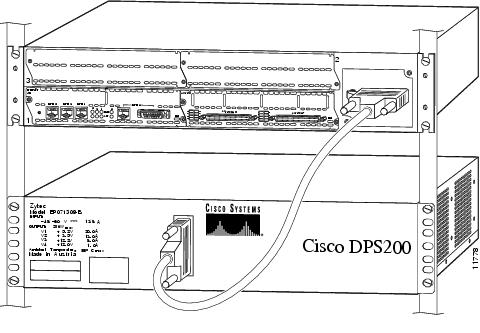
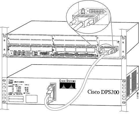
The Cisco 3640 router, when configured as a system controller supporting the AS5800 Universal Access Server, offers a Cisco DPS200 dual-redundant power shelf that provides AC-input or DC-input power. Power is delivered to the system controller using a dedicated, shielded cable assembly that connects to an adapter assembly from the Cisco 3640 rear panel, as shown in .
Figure 1 Cisco 3640 System Controller Connected to Dual-Redundant Power Shelf
The AC-input dual-redundant power supplies provide a total of 200 watts of power that operates with power line voltages between 90 and 254 VAC, and power line frequencies between 47 and 63 Hz, with no more than 5-percent distortion. The DC-input dual-redundant power supplies each provide between -40 and -72 VDC, with no more than 5-percent distortion. Either power supply combination—DC plus DC, or AC plus AC—can function in a current-sharing mode. The dual-redundant power supplies support load sharing and are hot-swappable.
The power subsystem includes a single 19-inch rack-mount shelf unit that will accommodate two AC-input or DC-input power supply units. The power subsystem is self-cooled by side-to-side airflow that is propelled by its own fan tray assembly. The fan tray is hot-swappable; however, you must install the new fan tray assembly immediately, or the system will shut down.
The power shelf can deliver higher levels of output voltage than those required by the system controller; however, both the system controller design and the interconnect cable assembly are designed to compensate for this.
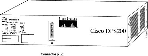
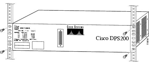
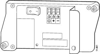
shows a front view of the Cisco DPS200 dual-redundant power shelf.
Figure 2 Cisco DPS200 Dual-Redundant Power Shelf Front View
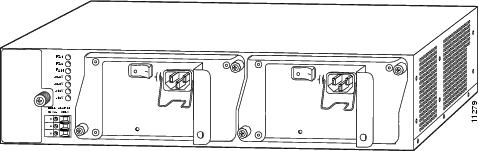
shows a rear view of the Cisco DPS200 dual-redundant AC-input power shelf. You must rack-mount your power shelf so that the front panel faces the same direction as the Cisco 3640 system controller rear panel. The power shelf can be installed either directly above or directly below the system controller in a rack.
Figure 3 Cisco DPS200 Dual-Redundant AC-Input Power Shelf Rear View
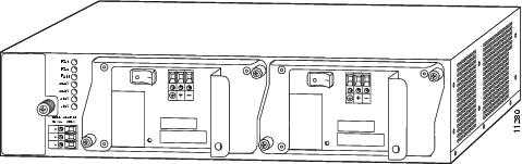
shows a rear view of the Cisco DPS200 dual-redundant DC-input power shelf.
Figure 4 Cisco DPS200 Dual-Redundant DC-Input Power Shelf Rear View
LEDs
LEDs are located on the subsystem rear panel, as shown in , to indicate power and fan status. There are seven LEDs to help you determine system status. describes LED status information.
Table 1 LED Status Information
Tips
•
•
•
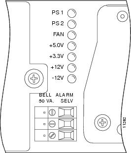
shows the dual-redundant power shelf rear panel LED display and alarm connectors.
Figure 5 Rear Panel LED Display and Alarm Connectors
CautionAlarms are safety extra-low voltage (SELV) circuits. SELV circuits should only be connected to other SELV circuits.
Safety Guidelines
This section provides safety and ESD-prevention guidelines to help you avoid injury to yourself and avoid damage to the equipment, and includes the following information:
•
•
Electrical Equipment Guidelines
This section provides basic guidelines to follow when you are working with any electrical equipment:
•
•
•
•
•
•
Telephone Wiring Guidelines
This section provides basic guidelines to follow when you are working with any equipment that is connected to telephone wiring or other network cabling:
•
•
•
•
Preventing Electrostatic Discharge Damage
Electrostatic discharge (ESD) damage, which can occur when electronic cards or components are improperly handled, results in complete or intermittent failures. Port adapters and processor modules consist of printed circuit boards that are fixed in metal carriers. Electromagnetic interference (EMI) shielding and connectors are integral components of the carrier. Although the metal carrier helps to protect the board from ESD, use a preventive antistatic strap during handling.
The following are guidelines to follow to prevent ESD damage:
•
•
•
•
•
•
•
•
CautionFor safety, periodically check the resistance value of the antistatic strap. The measurement should be between 1 and 10 megohms.
Safety Warnings
Safety warnings appear throughout this publication in procedures that, if performed incorrectly, may harm you. A warning symbol precedes each warning statement. To see translations of safety warnings pertaining to the dual-redundant power shelf, refer to the Cisco DPS200 Dual-Redundant Power Shelf Regulatory Compliance and Safety Information document that shipped with your system. To see translations of safety warnings pertaining to the Cisco 3640 router that connects to your dual-redundant power shelf, refer to the Regulatory Compliance and Safety Information document that shipped with your router.
Warning
This warning symbol means danger. You are in a situation that could cause bodily injury. Before you work on any equipment, be aware of the hazards involved with electrical circuitry and be familiar with standard practices for preventing accidents. To see translations of the warnings that appear in this publication, refer to the Regulatory Compliance and Safety Information document that accompanied this device.
Waarschuwing Dit waarschuwingssymbool betekent gevaar. U verkeert in een situatie die lichamelijk letsel kan veroorzaken. Voordat u aan enige apparatuur gaat werken, dient u zich bewust te zijn van de bij elektrische schakelingen betrokken risico's en dient u op de hoogte te zijn van standaard maatregelen om ongelukken te voorkomen. Voor vertalingen van de waarschuwingen die in deze publicatie verschijnen, kunt u het document Regulatory Compliance and Safety Information (Informatie over naleving van veiligheids- en andere voorschriften) raadplegen dat bij dit toestel is ingesloten.
Varoitus Tämä varoitusmerkki merkitsee vaaraa. Olet tilanteessa, joka voi johtaa ruumiinvammaan. Ennen kuin työskentelet minkään laitteiston parissa, ota selvää sähkökytkentöihin liittyvistä vaaroista ja tavanomaisista onnettomuuksien ehkäisykeinoista. Tässä julkaisussa esiintyvien varoitusten käännökset löydät laitteen mukana olevasta Regulatory Compliance and Safety Information -kirjasesta (määräysten noudattaminen ja tietoa turvallisuudesta).
Attention Ce symbole d'avertissement indique un danger. Vous vous trouvez dans une situation pouvant causer des blessures ou des dommages corporels. Avant de travailler sur un équipement, soyez conscient des dangers posés par les circuits électriques et familiarisez-vous avec les procédures couramment utilisées pour éviter les accidents. Pour prendre connaissance des traductions d'avertissements figurant dans cette publication, consultez le document Regulatory Compliance and Safety Information (Conformité aux règlements et consignes de sécurité) qui accompagne cet appareil.
Warnung Dieses Warnsymbol bedeutet Gefahr. Sie befinden sich in einer Situation, die zu einer Körperverletzung führen könnte. Bevor Sie mit der Arbeit an irgendeinem Gerät beginnen, seien Sie sich der mit elektrischen Stromkreisen verbundenen Gefahren und der Standardpraktiken zur Vermeidung von Unfällen bewußt. Übersetzungen der in dieser Veröffentlichung enthaltenen Warnhinweise finden Sie im Dokument Regulatory Compliance and Safety Information (Informationen zu behördlichen Vorschriften und Sicherheit), das zusammen mit diesem Gerät geliefert wurde.
Avvertenza Questo simbolo di avvertenza indica un pericolo. La situazione potrebbe causare infortuni alle persone. Prima di lavorare su qualsiasi apparecchiatura, occorre conoscere i pericoli relativi ai circuiti elettrici ed essere al corrente delle pratiche standard per la prevenzione di incidenti. La traduzione delle avvertenze riportate in questa pubblicazione si trova nel documento Regulatory Compliance and Safety Information (Conformità alle norme e informazioni sulla sicurezza) che accompagna questo dispositivo.
Advarsel Dette varselsymbolet betyr fare. Du befinner deg i en situasjon som kan føre til personskade. Før du utfører arbeid på utstyr, må du vare oppmerksom på de faremomentene som elektriske kretser innebærer, samt gjøre deg kjent med vanlig praksis når det gjelder å unngå ulykker. Hvis du vil se oversettelser av de advarslene som finnes i denne publikasjonen, kan du se i dokumentet Regulatory Compliance and Safety Information (Overholdelse av forskrifter og sikkerhetsinformasjon) som ble levert med denne enheten.
Aviso Este símbolo de aviso indica perigo. Encontra-se numa situação que lhe poderá causar danos físicos. Antes de começar a trabalhar com qualquer equipamento, familiarize-se com os perigos relacionados com circuitos eléctricos, e com quaisquer práticas comuns que possam prevenir possíveis acidentes. Para ver as traduções dos avisos que constam desta publicação, consulte o documento Regulatory Compliance and Safety Information (Informação de Segurança e Disposições Reguladoras) que acompanha este dispositivo.
¡Advertencia! Este símbolo de aviso significa peligro. Existe riesgo para su integridad física. Antes de manipular cualquier equipo, considerar los riesgos que entraña la corriente eléctrica y familiarizarse con los procedimientos estándar de prevención de accidentes. Para ver una traducción de las advertencias que aparecen en esta publicación, consultar el documento titulado Regulatory Compliance and Safety Information (Información sobre seguridad y conformidad con las disposiciones reglamentarias) que se acompaña con este dispositivo.
Varning! Denna varningssymbol signalerar fara. Du befinner dig i en situation som kan leda till personskada. Innan du utför arbete på någon utrustning måste du vara medveten om farorna med elkretsar och känna till vanligt förfarande för att förebygga skador. Se förklaringar av de varningar som förkommer i denna publikation i dokumentet Regulatory Compliance and Safety Information (Efterrättelse av föreskrifter och säkerhetsinformation), vilket medföljer denna anordning.
Follow these guidelines to ensure general safety:
•
•
•
•
•
•
Input Specifications
AC-input voltage range is between 90 and 254 VAC. The frequency range is between 47 and 63 Hz, and distortion is within 5 percent on the AC-input. DC-input voltage range is between -40 and -72 VDC.
Peak AC-inrush current does not exceed 70A. Transient can occur anywhere in the positive or negative alternance of the input voltage; however, transient does not last more than one alternance.
Note
Note
Output Specifications
The AC-input or DC-input power supplies are designed to support current sharing and provide redundancy; however, the power supply can support a fully configured system when a second power supply is not available.
Each power supply will shut down if output current exceeds 105 to 135 percent of its maximum startup current rating, and will automatically restart when failing conditions are removed in an overpower condition.
In an overvoltage condition, if any output exceeds the specified thresholds, all voltages are shut down. After the failed voltage condition is removed, you must recycle the unit to resume operation.
Current sharing is divided so that one power supply carries 40 percent of the load, and one power supply carries 60 percent of the load on the +5V, +12V, and -12V output voltages. If the load is less than 20 percent, current sharing is not needed.
and list output voltage and output current specifications.
Table 2
Maximum
5.25V
12.60V
-13.20V
Nominal
5.15V
12.20V
-12.00V
Minimum
5.00V
11.80V
-10.80V
1 The sum of the output power from the 3.3V and 5.2V outputs shall not exceed 154 watts.
Output Voltage
Table 3
Maximum
15.00A
8.00A
-1.50A
Minimum
2.00A
0.00A
-0.00A
Startup (5 seconds)
19.00A
11.00A
-2.50A
Output Current
lists ripple and noise specifications. Measurements are based upon the power supply output connector at minimum and maximum loads, from DC to 20 mHz.
Table 4 Ripple and Noise
Ripple and Noise (measured in the system)
50 mV
100 mV
100 mV
Ripple and Noise (measured in the bench)
50 mV
100 mV
100 mV
lists environmental specifications, which are designed to meet any specified combination of operating ambient conditions, and after exposure to any combination of nonoperating ambient conditions.
Table 5
Temperature:
Operating
Nonoperating32° to 122° F (0° to 50° C); 113° F (45° C) at 10,000 feet, full load, and 90 to 254 VRMS
104° to 158° F (-40° to 70° C)Humidity:
Operating
Nonoperating10 to 90%, noncondensing
10 to 95%, noncondensingThermal shock:
Operating
Nonoperating23° to 113° F (-5° to 45° C) at 32.9° F (0.5° C) per minute
-113° to 158° F (-25° to 70° C) with changeover time between 2 and 3 minutesDC range
-40 to -72 VDC
AC range
90 to 254 VAC
Shock
IEC 68-2-27, test Ea
Drop
IEC 68-2-31, test AC at a drop distance of 50 mm while operating
Tipover
IEC 68-2-31, test AC
Radio frequency interference
FCC Part 15, class A for radiated and conducted emissions
CISPR 22 (EN55022), class B for radiated and conducted emissions
Bellcore generic requirements GR-1089-CORE, Issue 1, November 1994, class B
ETS-300 132-2 Power Supply Input of Telecom System InterfacesThermal shutdown
149° F (65° C) at sea level, 280-watt load, nonredundant, and minimum input voltage
MTBF1
250,000 hours of operation at 90% lower confidence level at 77° F (25° C), 120 VRMS/-48VCD input and 100% load
Regulatory compliance
UL 1950
CAN/CSA C22.2 No. 950
EN 60950
IEC 950
TS001
AS3260Immunity requirements
IEC 1000-4-2/EN61000-4-2, ESD up to 15 Kv
IEC 1000-4-3/EN61000-4-3, ENV50140, RFI 10v/m
IEC 1000-4-4/EN61000-4-4, Electrical Fast Transients Level 4
IEC 1000-4-5/EN61000-4-5, Surge Level 2, 1Kv
IEC 1000-4-6/EN61000-4-6, ENV50141, radio frequency common mode, Levels 10V (rms) modulated AM 80%, kHz, 150-ohm source impTelco requirements
Bellcore NEBS2 GR-63-CORE
Bellcore NEBS GR-1089 CORE Sections 2,3,6,7,8,9
Bellcore TR-TSY-000513
Bellcore GR-78-CORE
Bellcore GR-89-CORE
Bellcore TR-TSY-001003
FTZ 19Pf1 1 Deutsche Bundespost
BTNR 2511
CEPT EC T/TR02-02
ETS 300 132-2
1 MTBF = Mean Time Between Failures.
2 NEBS = Network Equipment-Building System.
Environmental Specifications
Interconnect Cable Connectors and Signals
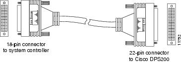
The dual-redundant power shelf is designed with a dedicated interconnect cable [part number SC-PWR-CAB(=)] that includes Molex Minifit connectors on either end, as shown in .
Figure 6 interconnect Cable
The cable connection to the power shelf uses a 22-pin cable connector; the cable connection to the system controller uses an 18-pin cable connector. lists DC-output pin connector definitions for the 22-pin connector that attaches to the power shelf.
Table 6 r22-Pin Connector Pin Definitions
lists pin connector definitions for the 18-pin connector that attaches to the system controller.
Table 7
18-Pin Connector Pin Definitions
The interconnect cable plugs into the system controller so that the boot covers the power switch located on the system controller rear panel, as shown in .
Figure 7 Interconnect Cable Connector Attached to System Controller
Warning
Only trained and qualified personnel should be allowed to install or replace this equipment.
Warning
Never defeat the ground conductor or operate the equipment in the absence of a suitably installed ground conductor. Contact the appropriate electrical inspection authority or an electrician if you are uncertain that suitable grounding is available.
Rack-Mounting Your Dual-Redundant Power Shelf
This section describes steps to rack-mount your dual-redundant power shelf in a 19-inch, 4-post rack or standard telco rack, which connects to a Cisco 3640 system controller.
Warning
Do not work on the system or connect or disconnect cables during periods of lightning activity.
Warning
To prevent bodily injury when mounting or servicing this unit in a rack, you must take special precautions to ensure that the system remains stable. The following guidelines are provided to ensure your safety:
•
•
•
List of Parts and Tools
The following parts and tools are needed to install your dual-redundant power shelf:
•
•
•
•
•
•
•
•
•
•
•
•
•
•
•
•
Installing Your Dual-Redundant Power Shelf in a 4-Post Rack
This section describes how to rack-mount your dual-redundant power shelf in a standard 4-post rack. Refer to the Cisco 3640 System Controller Installation and Configuration Guide that shipped with your Cisco 3640 system controller for information on how to rack-mount your system controller.
Use the following steps to install your dual-redundant power shelf in a 4-post rack:
Step 1
Step 2
Step 3
Step 4
Step 5
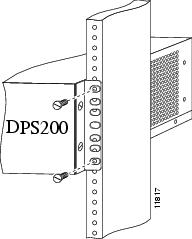
Figure 8 Attaching Rack-Mount Brackets to the Power Shelf
Step 6
This completes the procedure for installing your power shelf in a 4-post rack. Proceed to the section "Connecting the Ground Lug."
Installing Your Dual-Redundant Power Shelf in a Telco Rack
This section describes how to rack-mount your dual-redundant power shelf in a telco rack. Refer to the Cisco 3640 System Controller Installation and Configuration Guide that shipped with your Cisco 3640 system controller for information on how to rack-mount your system controller.
Use the following steps to install your dual-redundant power shelf in a telco rack:
Step 1
Step 2
Step 3
Step 4
Step 5
Figure 9 Attaching Rack-Mount Brackets to the Power Shelf
Step 6
This completes the procedure for installing your power shelf in a telco rack. Proceed to the next section "Connecting the Ground Lug."
Connecting the Ground Lug
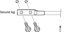
Your dual-redundant power shelf is equipped with a double ground lug and two screws for added safety.
Warning
When installing the unit, the ground connection must always be made first and disconnected last.
Use the following steps to connect your ground lugs to the power shelf chassis:
Step 1
Step 1
Step 2
Step 3
Figure 10 Connecting the Ground Lug
Connecting Your Cables
Warning
Do not touch the power supply when the power cord is connected. For systems with a power switch, line voltages are present within the power supply even when the power switch is off and the power cord is connected. For systems without a power switch, line voltages are present within the power supply when the power cord is connected.
Warning
This equipment is intended to be grounded. Ensure that the host is connected to earth ground during normal use.
Warning
Incorrect connection of this or connected equipment to a general purpose outlet could result in a hazardous situation.
Warning
This equipment is to be installed and maintained by service personnel only as defined by
AS/NZS 3260 Clause 1.2.14.3 Service Personnel.
Warning
Before working on equipment that is connected to power lines, remove jewelry (including rings, necklaces, and watches). Metal objects will heat up when connected to power and ground and can cause serious burns or weld the metal object to the terminals.
This section describes power shelf cable connections, and includes the following information:
•
Connecting Your Interconnect Cable
Use the following steps to connect your interconnect cable:
Step 1
Step 2
Step 3
Step 4
Note
Step 5
This completes the procedure for connecting the interconnect cable.
Connecting Your Power Cables
Warning
Care must be given to connecting units to the supply circuit so that wiring is not overloaded.
This section describes AC-input and DC-input power connections, and includes the following information:
•
•
Refer to the sections that support your site's own configuration needs.
Connecting AC-Input Power Cables
Warning
The device is designed to work with TN power systems.
Use these steps to connect your AC-input power cables to the power shelf:
Step 1
Step 2
Step 3
Step 4
This completes the procedure for connecting your AC power cables.
Connecting DC-Input Power Cables
Warning
Before performing any of the following procedures, ensure that power is removed from the DC circuit. To ensure that all power is OFF, locate the circuit breaker on the panel board that services the DC circuit, switch the circuit breaker to the OFF position, and tape the switch handle of the circuit breaker in the OFF position.
Warning
This unit is intended for installation in restricted access areas. A restricted access area is where access can only be gained by service personnel through the use of a special tool, lock and key, or other means of security, and is controlled by the authority responsible for the location.
Warning
Secure all power cabling when installing this unit to avoid disturbing field-wiring connections.
Warning
After wiring the DC power supply, remove the tape from the circuit breaker switch handle and reinstate power by moving the handle of the circuit breaker to the ON position.
Warning
A readily accessible two-poled disconnect device must be incorporated in the fixed wiring.
Use these steps to connect your DC-input power cables to the power shelf:
Step 1
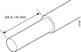
Step 2
Figure 11 Stripped DC Cable Wire
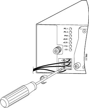
Step 3
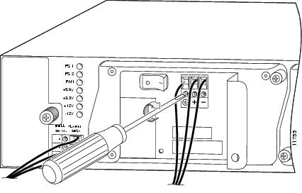
Figure 12 Connecting DC-Input Cables to Power Shelf Terminal Block
Warning
The illustration () shows the DC power supply terminal block. Wire the DC-input power supply using the appropriate wire terminations at the wiring end, as illustrated. The proper wiring sequence is ground to ground, positive to positive (line to L), and negative to negative (neutral to N). Note that the ground wire should always be connected first and disconnected last.
Figure 13 DC Power Supply Terminal Block
Step 4
Step 5
This completes the procedure for connecting your DC power cables.
Connecting Alarm Cables
Use these steps to connect your alarm cables to the power shelf:
Step 1
Step 2
Step 3
Figure 14 Connecting Alarm Cables
Step 4
This completes the procedure for connecting your alarm cables.
Removing and Replacing Your Power Supply
This section describes steps to remove and replace both AC-input and DC-input power supplies. Refer to the section that supports your site's configuration needs.
List of Parts and Tools
The following parts and tools are needed to remove and replace the power module:
•
•
•
•
•
•
•
•
•
Removing and Replacing Your AC-Input Power Supply
The follow procedures describe steps to remove and replace your AC-input power supply and include the following sections:
•
•
•
Disconnecting Power from an AC-Input Dual-Redundant Power Shelf
Use the following steps to disconnect power from an AC-input dual-redundant power shelf:
Step 1
Step 2
Step 3
•
•
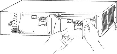
Removing Your AC-Input Power Module
Use the following steps to remove your AC-input power supply:
Step 1
Step 2
Step 3
Step 4
Figure 15 Removing the AC-Input Power Supply
This completes the procedure for removing your AC-input power supply. Proceed to the section "Replacing Your AC-Input Power Supply."
Replacing Your AC-Input Power Supply
Use the following steps to install your AC-input power supply:
Step 1
Step 2
Step 3
Step 4
Step 5
Step 6
This completes the procedure for replacing your AC-input power supply.
Removing and Replacing Your DC-Input Power Supply
The follow procedures describe steps to remove and replace your DC-input power supply and include the following sections:
•
•
•
Warning
Before completing any of the following steps, and to prevent short-circuit or shock hazards, verify power is removed from the DC circuit. To ensure that all power is OFF, locate the circuit breaker on the panel board that services the DC circuit, switch the circuit breaker to the OFF position, and tape the switch handle of the circuit breaker in the OFF position.
Warning
When installing the unit, the ground connection must always be made first and disconnected last.
Disconnecting Power from a DC-Input Dual-Redundant Power Shelf
Use the following steps to disconnect power from a DC-input dual-redundant power shelf:
Step 1
Step 2
Step 3
•
•
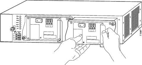
Removing Your DC-Input Power Supply
Use the following steps to remove your DC-input power supply:
Step 1
Step 2
Note
Step 3
Note
Step 4
Figure 16 Removing the DC-Input Power Supply
This completes the procedure for removing the DC-input power supply. Proceed to the section "Replacing Your DC-Input Power Supply."
Replacing Your DC-Input Power Supply
The following section describes steps to install your DC-input power supply:
Step 1
Step 2
Step 3
Step 4
Step 5
Step 6
Warning
The illustration () shows the DC power supply terminal block. Wire the DC-input power supply using the appropriate wire terminations at the wiring end, as illustrated. The proper wiring sequence is ground to ground, positive to positive (line to L), and negative to negative (neutral to N). Note that the ground wire should always be connected first and disconnected last.
Figure 17 DC Power Supply Terminal Block
Step 7
This completes the procedure for replacing your DC-input power supply.
Warning
After wiring the DC power supply, remove the tape from the circuit breaker switch handle and reinstate power by moving the handle of the circuit breaker to the ON position.
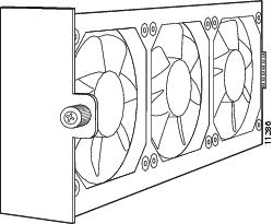
Removable Fan Tray Assembly
Your dual-redundant power shelf is equipped with a removable fan tray assembly, which is located on the left side of the dual-redundant power shelf when viewing the power shelf from the rear. The fan tray assembly consists of three fans that provide adequate airflow (from side to side) within the power shelf. The fan tray assembly receives -12 VDC power through the power harness, which connects to the power shelf backplane. If any one of the fans fails, a warning signal is displayed, causing the fan indicator LED on the power shelf rear panel to light. shows the removable fan tray assembly.
Figure 18 Removable Fan Tray Assembly
The fan tray assembly draws cooling air in through the intake vent on the right side of the chassis (when viewing the chassis from the front) and moves the air across the internal components and out the exhaust vent on the left side of the chassis. The left and right sides of the power shelf must remain unobstructed to ensure adequate airflow and to prevent overheating inside the power shelf chassis. We recommend that you have three inches of clearance on both sides of the power shelf.
CautionTo ensure adequate airflow across the power supplies, a power supply or power supply filler plate must be installed in each power supply bay.
CautionUse care when removing or replacing your fan tray; keep your fingers away from the fan blades.
Removing and Replacing Your Fan Tray
This section lists the required parts and tools to help you remove and replace your fan tray assembly seated in your dual-redundant power shelf.
List of Parts and Tools
The following parts and tools are needed to remove and replace the fan tray assembly:
•
•
•
•
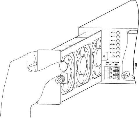
Removing Your Fan Tray
The following section describes steps to remove the fan tray from your power shelf:
Step 1
Step 1
Step 2
Step 3
Figure 19 Removing the Fan Tray Assembly
This completes the procedure for removing the fan tray assembly. Proceed to the section "Replacing the Fan Tray Assembly."
Replacing the Fan Tray Assembly
Use the following steps to replace the fan tray assembly in your dual-redundant power shelf:
Step 1
Step 2
Step 3
Tips
•
This completes the procedure for replacing the fan tray subchassis. For additional information and support documentation, refer to the next section "Cisco Connection Online."
Cisco Connection Online
Cisco Connection Online (CCO) is Cisco Systems' primary, real-time support channel. Maintenance customers and partners can self-register on CCO to obtain additional content and services.
Available 24 hours a day, seven days a week, CCO provides a wealth of standard and value-added services to Cisco's customers and business partners. CCO services include product information, software updates, release notes, technical tips, the Bug Navigator, configuration notes, brochures, descriptions of service offerings, and download access to public and authorized files.
CCO serves a wide variety of users through two interfaces that are updated and enhanced simultaneously—a character-based version and a multimedia version that resides on the World Wide Web (WWW). The character-based CCO supports Zmodem, Kermit, Xmodem, FTP, and Internet e-mail, and is excellent for quick access to information over lower bandwidths. The WWW version of CCO provides richly formatted documents with photographs, figures, graphics, and video, as well as hyperlinks to related information.
You can access CCO in the following ways:
•
•
•
•
•
For a copy of CCO's Frequently Asked Questions (FAQ), contact cco-help@cisco.com. For additional information, contact cco-team@cisco.com.
Note
78-5276-01