Feedback
Table Of Contents
Configuration Using the Command-Line Interface
Configuring Access and Security Parameters
Host Name, Enable Secret Password, and Time Stamps
Configuring WAN and User-Side Interfaces
Setting the Ethernet Port IP Address
Configuring a T1-WAN Port for a WAN Connection
Verifying the T1 Controller Configuration
Performing T1 Controller Loopback Diagnostics
Configuring TDM Cross-Connect (Data Pass-Through)
Configuring ATM Interface (T1-WAN Port and ADSL/SHDSL Port)
Verifying Your ATM Interface Configuration
Verifying the SHDSL Controller Configuration
Configuring Basic Settings for the Serial Port
Configuring Analog Voice Ports
Configuring Digital Voice Ports
Tuning Analog and Digital Voice-Port Settings
Verifying Your Analog or Digital Voice-Port Configuration
Configuring Synchronized Clocking
Clocking Configuration Procedure
Configuring Clock Recovery Through a T1 Port
Configuring a T1 Controller for Loop Timing
Configuring Clock Recovery Through the Serial Port
Clock Recovery Through an ADSL or SHDSL Port
Configuring a Hierarchy of Backup Clock Sources
Configuring Backup Clock Sources
Configuration Using the Command-Line Interface
This chapter describes how to configure the Cisco IAD manually, and includes procedures for configuring features and interfaces that are not covered in the setup command facility. Before proceeding with manual configuration, read "Cisco IOS Software Basics," to familiarize yourself with the command-line interface (CLI).
This chapter contains the following sections:
•
Configuring Access and Security Parameters
•
•
•
Configuring Access and Security Parameters
Configure basic access and security parameters:
•
Tip
Host Name, Enable Secret Password, and Time Stamps
Assign a host name, specify an enable secret password, and turn on time stamps:
•
•
•
Step 1
Router(config)# hostname hostnameRouter(config)# enable secret yourpasswordRouter(config)# service password-encryptionRouter(config)# service timestamps debug datetime msecRouter(config)# service timestamps log datetime msecRouter(config)#
Note
Step 2
Router(config)# exitStep 3
Router# disableStep 4
Router> enablePassword:Router# show privilegeCurrent privilege level is 15Router#
Local AAA Security
For information about configuring authentication, authorization, and accounting (AAA) for controlling user access, see the Cisco IOS Security Configuration Guide for your Cisco IOS software release.
Log-in Banner
For information on creating a log-in banner see the "Managing Connections, Menus, and System Banners" section under "Cisco IOS User Interfaces" in the Cisco IOS Configuration Fundamentals Configuration Guide for your Cisco IOS software release.
Configuring WAN and User-Side Interfaces
Complete the following tasks to place the Cisco IAD into service with an initial configuration that supports the installed user-side and wide-area network (WAN) interfaces:
•
•
•
•
•
•
•
•
When you have completed the uplink and user interfaces, your Cisco IAD is ready to configure for specific functions. For specific configuration procedures see the appropriate documentation on CCO for the Cisco IOS software release installed on your Cisco IAD:
•
•
•
•
•
Setting the Ethernet Port IP Address
Complete this procedure to set an IP address for the Ethernet port.
Note
After the Ethernet port is configured, you can either configure the Cisco IAD remotely through a Telnet connection, or you can continue using the console or auxiliary port.
Configuring a T1-WAN Port for a WAN Connection
Cisco IAD2421 series IADs have a T1-WAN port that supports balanced T1 per ANSI T1.403 and has a built-in CSU/DSU.
To configure the basic T1 controller settings to support Asynchronous Transfer Mode (ATM), Point-to-Point Protocol (PPP), high-level data link control (HDLC), or Frame Relay (FR), complete the following steps beginning in global configuration mode:
For additional information about configuring specific features, see the following references:
•
•
•
For information about obtaining the referenced documentation, see the "Obtaining Documentation" section.
Configuring a T1-PBX Port
Cisco IAD2420 series IADs for digital PBX interface have a T1-PBX port with a balanced T1 interface per ANSI T1.403, and they contain a built-in CSU/DSU. The T1-PBX port supports 24 digital voice lines.
To configure the basic T1 controller settings on the T1-PBX port, complete the following steps beginning in global configuration mode:
Verifying the T1 Controller Configuration
To verify that a controller is up and no alarms or errors are detected, enter the show controller T1 command in EXEC mode:
Router# show controller T1 {0 | 1}Error counters are recorded over a 24-hour period in 15-minute intervals. In verifying initial controller configuration, the relevant data is in the current interval.
Example output for a T1-WAN or T1-PBX port
Router# show controller T1 0 or show controller T1 1T1 is up.Applique type is Channelized T1Cablelength is shortNo alarms detected.Framing is ESF, Line Code is AMI, Clock Source is Line.Data in current interval (240 seconds elapsed):0 Line Code Violations, 0 Path Code Violations0 Slip Secs, 0 Fr Loss Secs, 0 Line Err Secs, 0 Degraded Mins0 Errored Secs, 0 Bursty Err Secs, 0 Severely Err Secs, 0 Unavail SecsData in Interval 1:0 Line Code Violations, 8 Path Code Violations11 Slip Secs, 26 Fr Loss Secs, 0 Line Err Secs, 0 Degraded Mins0 Errored Secs, 0 Bursty Err Secs, 0 Severely Err Secs, 26 Unavail SecsTotal Data (last 1 15 minute intervals):0 Line Code Violations, 8 Path Code Violations,11 Slip Secs, 26 Fr Loss Secs, 0 Line Err Secs, 0 Degraded Mins,0 Errored Secs, 0 Bursty Err Secs, 0 Severely Err Secs, 26 Unavail SecsRouter#Performing T1 Controller Loopback Diagnostics
To perform T1 controller loopback diagnostics as needed, complete the following steps in controller configuration mode:
After each controller is set up correctly, clear the counters and look for ongoing line violations and errors. To do this, enter the clear controller command followed by the show controller command:
Router# clear controller t1 0Router# show controller t1 0Router# clear controller t1 1Router# show controller t1 1In the display output, focus on the data in the current interval. Error counters do not increase if the controller is configured correctly.
Note
Table 4-1 provides a list of T1 alarm conditions and descriptions relevant to the Cisco IAD.
For more information about controllers, see the "Channelized E1 and Channelized T1 Setup Commands" section of the Dial Solutions Command Reference for your release of Cisco IOS software.
Configuring TDM Cross-Connect (Data Pass-Through)
The Time Division Multiplexing (TDM) cross-connect function allows you to create one or more TDM groups on a controller. Each TDM group is a block of contiguous or noncontiguous 64-kbps timeslots that function as a clear channel.
You can cross-connect TDM groups as follows:
•
•
To configure TDM cross-connect, complete the following steps, beginning in controller configuration mode:
Configuring ATM Interface (T1-WAN Port and ADSL/SHDSL Port)
Default Configuration
If your Cisco IAD has an ADSL, SHDSL, or T1-WAN port, a default ATM configuration is automatically enabled when you enter the mode atm controller command. The default ATM configuration has the following operating parameters:
•
–
•
–
–
–
–
–
To configure the ATM interface parameters for your application, you need the following information:
•
•
•
•
•
To enter an ATM configuration, complete the following steps, beginning in global configuration mode:
Step 1
For a T1-WAN port:
Router(config)# controller t1 0
For an SHDSL port:
Router(config)# controller shdsl 0
For an ADSL port:
Go to step 6.
Enters controller configuration mode and the controller number.
Step 2
Router(config-ctrl)# mode atm
Enables ATM encapsulation and create logical ATM interface 0. Controller framing is automatically set to Extended SuperFrame (ESF). The linecode is automatically set to B8ZS.
Step 3
For SHDSL ports only:
Router(config-ctrl)# annex {a | b}
Specifies the regional operating parameters. Enter a for North America and b for Europe. The default is a.
Step 4
For SHDSL ports only:
Router(config-ctrl)# line-rate {auto | rate}
Specifies the DSL line rate for the SHDSL port. The range is 72 to 2312 kbps. The default is auto (negotiated between the SHDSL port and the DSLAM)
Note
Step 5
Router(config-ctrl)# exit
Exits from controller configuration mode.
Step 6
Router(config)# interface atm 0
Enters ATM configuration mode for interface ATM 0.
Step 7
Router(config-if)# ip-address IP-address
(Optional) Assigns an IP address to the ADSL or SHDSL ATM interface.
Step 8
Router(config-if)# atm uni-version version-number
(Optional) Specifies an ATM user network interface (UNI) version number.
Step 9
Router(config-if)# atm ilmi-keepalive seconds
(Optional) Enables Integrated Local Management Interface (ILMI) keepalives.
If you enable ILMI keepalives without specifying the seconds, the default time interval is 3 seconds.
Step 10
Router(config-if)# pvc [name] vpi/vci
Enters atm-virtual-circuit (interface-atm-vc) configuration mode, and configure a new ATM PVC by assigning a name (optional) and VPI/VCI numbers.
The default traffic shaping is UBR; the default encapsulation is AAL5+LLC/SNAP.
Step 11
Router(config-if-vc)# protocol ip IP-address
(Optional) Enables IP connectivity and create a point-to-point IP address for the VC.
Step 12
Router(config-if-vc)# vbr-rt peak-rate average-rate burst
(Optional) Configures the PVC for real-time variable bit rate (VBR) traffic shaping.
•
For SHDSL ports, set the peak rate for the trained line rate minus 8 kbps.
•
•
Step 13
Router(config-if-vc)# encapsulation {aal1 | aal2 | aal5ciscoppp | aal5mux | aal5nlpid | aal5snap}
(Optional) Configures the ATM adaptation layer (AAL) and encapsulation type.
•
•
•
•
•
•
Step 14
Router(config-if-vc)# exit
Exits from interface-atm-vc configuration mode.
Step 15
Repeat steps 10 through 14 for each additional ATM PVC to be configured.
Configures any additional ATM PVCs.
Step 16
For an ADSL port:
Router(config-if)# dsl operating-mode {ansi-dmt | auto itu-dmt | splitterless}
For an SHDSL port or a T1-WAN port:
Go to step 17.
Configures the ADSL interface to operate in a specified mode:
•
•
•
•
Step 17
Router(config-if)# no shutdown
Activates the ATM interface.
Step 18
Router(config-if)# exit
Exits from ATM interface configuration mode.
Step 19
Router(config)# exit
Exits from global configuration mode.
Verifying Your ATM Interface Configuration
To verify the ATM interface configuration, enter the show interface atm 0 EXEC command. The following example shows a typical output from the show interface atm 0 command:
Router# show interface atm 0ATM0 is up, line protocol is upHardware is PQUICC Atom1MTU 1500 bytes, sub MTU 1500, BW 2304 Kbit, DLY 20000 usec,reliability 255/255, txload 1/255, rxload 1/255Encapsulation ATM, loopback not setKeepalive not supportedEncapsulation(s):, PVC mode512 maximum active VCs, 4 current VCCsVC idle disconnect time:300 secondsLast input never, output never, output hang neverLast clearing of "show interface" counters neverInput queue:0/75/0/0 (size/max/drops/flushes); Total output drops:0Queueing strategy:None5 minute input rate 0 bits/sec, 0 packets/sec5 minute output rate 0 bits/sec, 0 packets/sec20486 packets input, 368419 bytes, 0 no bufferReceived 0 broadcasts, 0 runts, 0 giants, 0 throttles0 input errors, 0 CRC, 0 frame, 0 overrun, 0 ignored, 0 abort0 packets output, 0 bytes, 0 underruns0 output errors, 0 collisions, 0 interface resets0 output buffer failures, 0 output buffers swapped outRouter#Verifying the SHDSL Controller Configuration
To verify the SHDSL controller status and view the statistics, enter the show controller shdsl 0 EXEC command. The following example shows a typical output from the show controller shdsl 0 command:
Router# show controller shdsl 0SHDSL 0 controller UPSLOT 3:Globespan xDSL controller chipsetFrame mode:ATMConfigured Line rate:AutoLine Re-activated 1 times after system bootupLOSW Defect alarm:NoneCRC per second alarm:NoneLine termination:CPEFPGA Revision:9Current 15 min CRC:0Current 15 min LOSW Defect:0Current 15 min ES:0Current 15 min SES:0Current 15 min UAS:0Previous 15 min CRC:0Previous 15 min LOSW Defect:0Previous 15 min ES:0Previous 15 min SES:0Previous 15 min UAS:0Chipset Version: 1Firmware Version: R1.0Modem Status: DataLine rate: 2312 KbpsFramer Sync Status:In SyncRcv Clock Status:In the RangeLoop Attenuation: 3.1250 dBTransmit Power: 7.5 dBReceiver Gain: 18.420 dBSNR Sampling: 42Last Fail Mode: No FailureRouter#Configuring Basic Settings for the Serial Port
To display the default configuration for serial port 0, enter the show interface serial command.
Router# show interface serial
To configure basic settings for the serial port, complete the following steps beginning in global configuration mode:
Configuring Voice Ports
This section has separate procedures for analog and digital voice ports. Use the analog procedure to configure analog FXS and FXO voice ports. Use the digital procedure to configure the T1 digital voice port.
Verifying Voice-Port Configuration
Before entering voice-port configuration mode, enter:
Router> show voice port summaryThis command brings up a list of the existing voice ports with their slot/port numbers, signaling types, and status.
Note
To see the complete current configuration of an existing voice port, enter a show voice port command:
•
Router> show voice port slot/port•
Router> show voice port controller/DS0-groupTable 4-2 summarizes the physical and logical characteristics of the Cisco IAD voice ports.
Note
Configuring Analog Voice Ports
Cisco IAD2420 series IADs with analog voice chassis can have 8, 16, or 24 analog voice ports, with slot/port identification as follows:
•
•
•
To configure or change the basic analog voice-port settings, complete the following steps, as required, beginning in global configuration mode:
Step 1
Router(config)# voice-port slot/port
Enters voice-port configuration mode, and specify the voice port that you want to configure by entering the logical slot number and port number (see Table 4-2). The commands affect only the voice port you specify here.
Step 2
Router(config-voiceport)# codec
{g729r8 | g729ar8 | g726r32 |
g711alaw | g711ulaw}Specifies a nondefault voice compression codec. The g729ar8 value is the default.
Simultaneously active, on-net, voice calls support by codecs:
•
•
Nominal data rates for compression modes:
•
•
•
Step 3
Router(config-voiceport)# connection {tie-line | plar | plar opx} string
Configures a voice-port connection mode.
If the connection is to a PBX, use the tie-line option.
If the connection is for Private Line Auto Ringdown (PLAR) use the plar option.
If the connection is for PLAR Off-Premises eXtension (OPX), use the plar-opx option. With this option, the local voice port provides a local response before the remote voice port receives an answer, and FXO interfaces do not answer until the remote side answers.
Step 4
Router(config-voiceport)# signal
{loop-start | ground-start | did {wink-start | immediate | delay-dial}}Changes the signaling type for the voice port. The default is loop-start.
Step 5
Router(config-voiceport)# dial-type {pulse | dtmf}
(FXO only) Changes the transmit dial type. The default is dtmf.
Step 6
Router(config-voiceport)# cptone country
Configures the voice port for the local territory call progress tone setting. The call progress tone setting determines the settings for dialtone, busytone, and ringback tone.
The default for this command is northamerica. For a list of supported countries, see the Cisco IOS Voice, Video, and Fax Command Reference for the Cisco IOS software release installed on your Cisco IAD.
Step 7
Router(config-voiceport)# no shutdown
Activates the voice port. You should activate only those voice ports that you plan to use.
Step 8
Router(config-voiceport)# description string
Enters a description of the location or use of this voice port. You can enter as many as 255 characters.
Step 9
Exit from voice-port configuration mode and repeat Steps 1 through 8 for the remaining analog voice ports.
Configures any required voice ports.
Note
To configure tuning options for analog voice ports, see the "Tuning Analog and Digital Voice-Port Settings" section.
To configure dial peers, see the applicable voice service configuration section of the Cisco IOS Multiservice Applications Configuration Guide for the Cisco IOS software release installed on your Cisco IAD.
Configuring Digital Voice Ports
Cisco IAD2420 series IADs with digital voice chassis (Cisco IAD242x-1T1) have a T1-PBX port that supports a balanced T1 interface with a digital PBX. The T1-PBX interface supports as many as 24 voice lines (DS0s), with controller:DSO-group identification of 1:0 through 1:23.
To configure the basic T1 controller and digital voice port settings on the T1 PBX port, complete the following steps beginning in global configuration mode:
Step 1
Router(config)# controller t1 1
Enters controller configuration mode for controller 1(the trunk controller for the T1-PBX port).
Step 2
Router(config-controller)# mode
{cas | ccs cross-connect | ccs frame-forwarding}Enters CAS configuration mode and configure the T1 trunk to support signaling that matches the PBX signaling type:
•
•
•
Step 3
Router(config-controller-cas)# ds0-group ds0-group-no timeslots timeslot-list type {e&m-immediate | e&m-delay | e&m-wink |
fxs-ground-start | fxs-loop-start | fxo-ground-start | fxo-loop-start}Creates a DS0 group on the T1 trunk. A DS0 group can contain from 1 to 24 timeslots numbered from 0 to 23.
When configuring a DS0 group for a T1 line to a PBX, make sure that the timeslot numbers match the channels on the PBX. Contact the PBX administrator to determine which channels to use.
Timeslots with identical voice-port configuration can be assigned to one DS0 group.
Timeslots with nonidentical voice-port configurations must be assigned to different DS0 groups.
Note
Step 4
Repeat Step 3 for each additional DS0 group. After DS0 groups are defined, exit CAS configuration mode.
Configures additional DS0 groups on the T1 interface to the PBX. You can configure as many as 24 DS0 groups on a T1.
Step 5
Router(config)# voice-port 1:DS0-group
Enters voice-port configuration mode, and specifies the voice port that you want to configure. The logical slot for these voice ports is always 1 (for controller 1). The logical port is 0 to 23, corresponding to the DS0 group. The following commands affect the timeslots in this logical voice port.
Step 6
Router(config-voiceport)# dial-type {pulse | dtmf}
(FXO only) If this voice port supports rotary pulse dialing, changes the transmit dial type to pulse. The default is dtmf.
Step 7
Router(config-voiceport)# compand-type {u-law | a-law}
Changes the companding if necessary. The default is u-law (the North American mu-law ITU-T PCM encoding standard). Specify a-law to use the European a-law ITU-T PCM encoding standard.
Step 8
Router(config-voiceport)# no shutdown
Activates the voice port. You should activate only those voice ports that you plan to use.
Step 9
Exit from voice-port configuration mode and repeat Steps 5 through 8 for the remaining digital voice ports.
Configures any required digital voice ports.
Note
To configure voice-port tuning options, see the "Tuning Analog and Digital Voice-Port Settings" section.
To configure dial peers, see the applicable voice service configuration section of the Cisco IOS Multiservice Applications Configuration Guide for the Cisco IOS software release installed on your Cisco IAD.
Tuning Analog and Digital Voice-Port Settings
In most cases the default values for voice port settings are sufficient. However, for specific configurations of analog and digital voice ports, you can tune the voice port settings as needed.
To tune voice-port settings, complete the following steps, as necessary, in voice-port configuration mode:
Verifying Your Analog or Digital Voice-Port Configuration
You can test your analog or digital voice-port configuration by doing the following:
•
•
•
•
•
Troubleshooting Tips
If you are having trouble connecting a call and you suspect the problem is associated with voice-port configuration, you can try to resolve the problem by performing the following:
•
–
–
•
•
•
Configuring Basic IP Settings
To tune IP routing behavior and domain-name services, complete the following steps:
Step 1
Router(config)# ip subnet-zeroRouter(config)# no ip source-routeRouter(config)# ip classlessTable 4-3 describes the previous commands.
Step 2
Router(config)# ip domain-lookupRouter(config)# ip host ip-hostname ip-addressRouter(config)# ip domain-name wordRouter(config)# ip name-server primary-ip-addressRouter(config)# ip name-server secondary-ip-addressTable 4-4 describes the previous commands.
Configuring Synchronized Clocking
This section is divided into the following subsections:
•
•
Clocking Configuration Procedure
For voice and video applications, a single master clock source must be established. This section provides step-by-step procedures for configuring clocking without specifying a clock-source backup hierarchy.
Note
If multiple sources of network clock are available to the Cisco IAD—for example, a controller configured for clock source line and the serial port configured for clock rate line—you must assign a different priority to each clock source; otherwise, multiple clock sources can cause clocking conflicts. See the "Configuring a Hierarchy of Backup Clock Sources" section.
This section includes the following procedures:
•
•
•
•
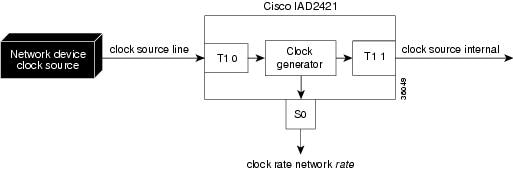
Configuring Clock Recovery Through a T1 Port
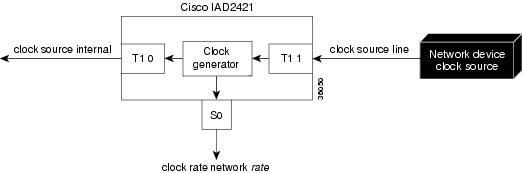
Figure 4-1 shows clock recovery from a network device connected to controller T1 0 (T1-WAN interface). Figure 4-2 shows clock recovery from a network device connected to controller T1 1 (T1-PBX interface).
Figure 4-1 Recovering Clock Through the T1-WAN Port
Figure 4-2 Recovering Clock Through the T1-PBX Port
To configure a T1 controller to recover external clock, complete the following steps beginning in global configuration mode:
Step 1
Router(config)# controller T1 {0 | 1}
Enters controller configuration mode for the controller that you are configuring for external clock recovery.
Step 2
Router(config-controller)# clock source line
Configures the controller to recover external clock.
Step 3
Router(config-controller)# exit
Exits controller configuration mode.
Step 4
Router(config)# controller T1 {0 | 1}
Enters controller configuration mode for the other controller, if it is installed.
Step 5
Router(config-controller)# clock source {internal | loop-timed | line}
If the second controller is not a backup clock source, configures it to use internal (system) clock or loop timing.
If the second controller is a backup clock source, configures it to recover external (line) clock1 .
Step 6
Router(config-controller)# exit
Exits controller configuration mode.
Step 7
Router(config)# network-clock base-rate [56k | 64k]
Sets the network clock base rate for the serial ports: 56k for T1. The default is 56k.
Step 8
Router(config)# interface serial 0
Enters interface configuration mode for serial port 0.
Step 9
Router(config-if)# clock rate network rate
Specifies a clock rate for the serial port. The rate must be a multiple (up to 32x) of the value set with the network-clock base-rate command—in other words, n x 56000 or n x 64000, where n = 1 to 32.
Step 10
Router(config-if)# exit
Exits interface configuration mode.
Step 11
Router(config-if)# ctrl z
Returns to privileged EXEC mode.
Step 12
Router# show network-clocks
Displays the network clock configuration.
1 Unless activated, a backup clock source automatically operates in loop-timed mode (although configured for external clock).
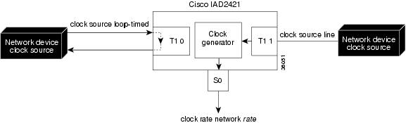
Configuring a T1 Controller for Loop Timing
A controller operates with loop timing under two conditions:
•
•
Note
Figure 4-3 shows an example of a loop-timed controller T1 0.
Figure 4-3 Loop-Timed Controller T1 0 (T1-WAN Port)
To configure loop timing on a T1 controller, complete the following steps beginning in global configuration mode:
Configuring Clock Recovery Through the Serial Port
Figure 4-4 shows clock recovery from a network device connected to the serial port.
Figure 4-4 Recovering Clock Through the Serial Port
Note
Set the serial port to DTE by connecting it to a DTE cable.
Note
To configure the serial port to recover network clock, complete the following steps beginning in global configuration mode:
Step 1
Router(config)# network-clock-select 1 serial 0
Configures the Cisco IAD to recover clock from the serial port (0).
The serial port must be set for DTE by a DTE cable.
Step 2
Router(config)# network-clock base-rate {56k | 64k}
Sets the network clock base rate for the serial port: 56k for T1. The default is 56k.
Step 3
Router(config)# interface serial 0
Enters interface configuration mode for the serial port.
Step 4
Router(config-if)# clock rate line rate
Sets the clock recovery rate for the rate of the incoming clock. This value must be a multiple of 8000.
Step 5
Router(config-if)# exit
Exits interface configuration mode.
Step 6
Router(config)# controller
{T1 | E1} 0Enters controller configuration mode for T1 0 if your Cisco IAD has a T1-WAN interface.
Step 7
Router(config-controller)# clock source {internal | loop-timed | line}
If controller T1 0 is not a backup clock source, configures it to use internal (system) clock or loop timing.
If controller T1 0 is a backup clock source, configures it to recover external (line) clock1 .
Step 8
Router(config-controller)# exit
Exits controller configuration mode.
Step 9
If your Cisco IAD has a T1-PBX port:
Router(config)# controller T1 1
If your Cisco IAD has an analog voice user interface, go to step 11.
Enters controller configuration mode for T1 1.
Step 10
If your Cisco IAD has a T1-PBX port:
Router(config-controller)# clock source {internal | loop-timed | line}
If controller T1 1 is not a backup clock source, configures it to use internal (system) clock or loop timing.
If controller T1 1 is a backup clock source, configures it to recover external (line) clock1.
Step 11
Router(config)# ctrl z
Returns to privileged EXEC mode.
Step 12
Router# show network-clocks
Displays the network clock configuration.
1 When not active, a backup clock source automatically operates in loop-timed mode (although configured for external clock).
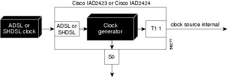
Clock Recovery Through an ADSL or SHDSL Port
If a DSL port is present (ADSL or SHDSL) , the DSL port is the first-priority clock source. Figure 4-5 shows a Cisco IAD obtaining clocking from a DSL interface.
Figure 4-5 Recovering Clock Through ADSL or SHDSL Port
Configuring Internal Clock
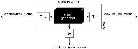
Figure 4-6 shows use of the Cisco IAD internal clock generator.
Figure 4-6 Cisco IAD Internal Clock Generation
Note
To configure the Cisco IAD to use its internal 2 Mhz. clock as the clock source, complete the following steps beginning in global configuration mode:
Step 1
Router(config)# network-clock-select 1 system
Configures the Cisco IAD to generate clock internally.
Step 2
Router(config)# controller T1 0
If your Cisco IAD has a T1-WAN port, enters controller configuration mode for T1 0.
Step 3
Router(config-controller)# clock source {internal | loop-timed | line}
If controller T1 0 is not a backup clock source, configures it to use internal (system) clock or loop timing.
If controller T1 0 is a backup clock source, configures it to use external (line) clock1 .
Step 4
Router(config-controller)# exit
Exits controller configuration mode.
Step 5
Router(config)# controller T1 1
If your Cisco IAD has a T1-PBX port, enters controller configuration mode for T1 1.
Step 6
Router(config-controller)# {clock source {internal | loop-timed | line}
If controller T1 1 is not a backup clock source, configures it to use internal (system) clock or loop timing.
If controller T1 1 is a backup clock source, configures it to use external (line) clock1.
Step 7
Router(config-controller)# exit
Exits controller configuration mode.
Step 8
Router(config)# network-clock base-rate 56k
Sets the network clock base rate for the serial port.
Step 9
Router(config)# interface serial 0
Enters interface configuration mode for the serial port.
Step 10
Router(config-if)# clock rate network rate
Specifies a clock rate for the serial port. The rate must be a multiple (up to 32x) of the value set with the network-clock base-rate command—in other words, n x 56000, where n = 1 to 32.
Step 11
Router(config-if)# exit
Exits interface configuration mode.
Step 12
Router(config)# Ctrl-Z
Returns to privileged EXEC mode.
Step 13
Router# show network-clocks
Displays the network clock configuration.
1 To function as a backup clock recovery source, a controller must be configured for external clock. It operates in loop-timed mode when not recovering clock. If a controller is specified as a backup clock source, you must configure it for external clock, but it automatically operates in loop-timed mode unless it is recovering clock due to loss of a higher-priority clock source.
Configuring a Hierarchy of Backup Clock Sources
You can define a hierarchy of backup clock sources. This tells the system where to look for clock if the primary clock source fails. If no backup clock sources are specified, the system switches to internal clock whenever an external clock source fails.
Configuring Backup Clock Sources
To configure a hierarchy of backup clock sources, complete the following steps beginning in global configuration mode:
Step 1
Router(config)# network-clock-select 1-4 [serial 0 | system | bvm | controller]
Specifies a clock selection priority from 1 to 4 for each clock source: 1 for the primary clock source; 2, 3, or 4 for backup clock sources.
You do not have to reenter any clock-source priorities that you entered previously.
Step 2
Router(config)# network-clock-switch [switch-delay-time | never] [restore-delay-time | never]
Configures the clock switching delay times.
The switch delay time option sets the delay time in seconds for switchover to the next-priority backup clock source.
The restore delay time option sets the delay time in seconds for reversion to a higher-priority clock source.
Step 3
Router(config)# controller T1
{0 | 1}If one of the T1 controllers is a primary or backup clock source, enters controller configuration mode for the controller.
Step 4
Router(config-controller)# clock source line
Configures the controller to recover external clock.
Step 5
Router(config-controller)# exit
Exits controller configuration mode.
Step 6
If the other T1 controller is a primary or backup clock source, repeat Steps 3, 4, and 5.
Note
Configures the other T1 controller to recover external clock.
Step 7
Router(config)# interface serial 0
If serial port 0 is a primary or backup clock source, enters interface configuration mode for serial port 0.
Step 8
Router(config-if)# clock rate line rate
Sets the clock recovery rate for the rate of the incoming clock. This value must be a multiple of 8000.
Verifying Your Configuration
You can perform the following tests at any time to verify the hardware or software configuration of a Cisco IAD:
•
•
•
•
The following example shows a typical running configuration with the initial configuration tasks completed:
Router# show running-configBuilding configuration...Current configuration:!version 12.1no service padservice timestamps debug datetimeservice timestamps log uptimeno service password-encryption!hostname iad001!enable secret 5 $1$xf8X$38Qbfc.8UfVFmsDLR61fh.enable password cisco!network-clock base-rate 56kip subnet-zero!mgcpmgcp call-agent 1.3.26.1 service-type mgcp version 0.1no mgcp timer receive-rtcpcall rsvp-sync!voice service voatm!session protocol aal2cac master!!!!!voice-card 0!!!controller T1 0mode atmframing esflinecode b8zs!!!!interface Ethernet0ip address 10.3.96.20 255.255.0.0no ip route-cacheno ip mroute-cache!interface Serial0no ip addressno ip route-cacheno ip mroute-cacheshutdown!interface ATM0no ip addressip mroute-cacheno atm ilmi-keepalivepvc 35/37vbr-rt 512 512 10vcci 2encapsulation aal2!pvc 40/41vbr-rt 512 512 10vcci 4encapsulation aal2!!ip classlessip route 192.168.254.254 255.255.255.255 1.3.0.1no ip http server!!map-class frame-relay 20dialer-list 1 protocol ip permitdialer-list 1 protocol ipx permit!voice-port 1/1!voice-port 1/2timeouts wait-release 3connection trunk 2105!voice-port 1/3!voice-port 1/4!voice-port 1/5shutdown!voice-port 1/6!voice-port 1/7!voice-port 1/8!dial-peer cor custom!!!dial-peer voice 3101 potsapplication mgcpappdestination-pattern 3101port 1/1!dial-peer voice 3102 potsdestination-pattern 3102port 1/2!dial-peer voice 3103 potsapplication mgcpappdestination-pattern 3103port 1/3!dial-peer voice 3104 potsdestination-pattern 3104port 1/4!dial-peer voice 3105 potsdestination-pattern 3105port 1/5!dial-peer voice 3106 potsshutdowndestination-pattern 3106port 1/6!dial-peer voice 2000 voatmdestination-pattern 2...session target ATM0 pvc 35/37codec g729ar8!dial-peer voice 2100 voipshutdowndestination-pattern 2105session target ipv4:1.3.96.21codec g711ulaw!dial-peer voice 2103 voatmdestination-pattern 2105called-number 3102session protocol aal2-trunksession target ATM0 pvc 40/41 100codec aal2-profile custom 110 g726r32!!line con 0transport input noneline aux 0line 2 3line vty 0 4password ciscologin!endSaving Configuration Changes
Enter the copy running-config startup-config command to save your configuration changes to nonvolatile random-access memory (NVRAM), so that the configuration is not lost if there is a system reload or power outage. For example:
Router# copy running-config startup-configBuilding configuration...It might take a minute or two to save the configuration to NVRAM. After the configuration has been saved, the following appears:
[OK]Router#