Table Of Contents
Installing and Connecting the Router
Installing the Router in a Rack
Attaching Rack-Mount Brackets to Cisco 2010 CGR Routers
Connecting to a Console Terminal or Modem
Connecting to the Serial Port with Microsoft Windows
Connecting to the Console Port with Mac OS X
Connecting to the Console Port with Linux
Installing the Cisco Microsoft Windows USB Device Driver
Installing the Cisco Microsoft Windows XP USB Driver
Installing the Cisco Microsoft Windows 2000 USB Driver
Installing the Cisco Microsoft Windows Vista USB Driver
Uninstalling the Cisco Microsoft Windows USB Driver
Uninstalling the Cisco Microsoft Windows XP and 2000 USB Driver
Uninstalling the Cisco Microsoft Windows Vista USB Driver
Connecting to the Auxiliary Port
Connecting WAN and LAN Interfaces
Connection Procedures and Precautions
Installing and Connecting the Router
This document describes how to install and connect Cisco Connected Grid Routers (CGR) 2010 to a LAN or WAN. The following sections provide technical details.
•
Installing the Router in a Rack
•
•
•
•
•
Note
Caution
Note
http://www.cisco.com/en/US/prod/collateral/routers/ps10967/ps10977/data_sheet_c78_593509.htmlWarning
Warning
Warning
Warning
Warning
Warning
Warning
Warning
Warning
Statement 1029
Warning
Warning
Warning
Warning
Warning
Warning
Warning
Caution
Warning
What you Need to Know
CLI Console Access
Use the new USB console port on the router to access the Cisco Internet Operating System (IOS) Command Line Interface (CLI) on the router and perform configuration tasks. A terminal emulation program, such as Microsoft Windows HyperTerminal, is required to establish communication between the router and a PC. See the "Connecting to a Console Terminal or Modem" section for instructions.
Note
Slot and Port Numbers
Cisco 2010 CGR have built in ports and new slots. The new slots accommodate new grid router WAN interface cards (GRWICs). See the "Slot, Port, and Interface Information" section on page 1-6 for slot and port numbering.
Before You Begin
Before installing and connecting a Cisco 2010 CGR router, read the safety warnings and gather the following tools and equipment:
•
•
•
–
–
•
In addition, depending on the type of modules you plan to use, you might need the following equipment to connect a port to an external network:
•
Note
•
•
•
•
•
•
Caution
Unpacking the Router
Do not unpack the router until you are ready to install it. If the final installation site will not be ready for some time, keep the chassis in its shipping container to prevent accidental damage. When you are ready to install the router, proceed with unpacking it.
The router, accessory kit, publications, and any optional equipment you ordered may be shipped in more than one container. When you unpack the containers, check the packing list to ensure that you received all of the items on the list.
Installing the Router in a Rack
The Cisco 2010 CGR can only be mounted in a rack.
Caution
Note
Rack-Mounting the Chassis
Cisco 2010 CGR can be installed in 19-inch (48.26-cm) standard rack.
You can mount the router in the following ways:
•
•
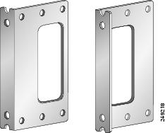
Figure 3-2 shows the rack-mount brackets used with the Cisco 2010 CGR.
Figure 3-1 Rack-Mount Brackets for the Cisco 2010 CGR
Attaching Rack-Mount Brackets to Cisco 2010 CGR Routers
For the Cisco 2010 CGR routers, use four of the supplied number-8 Phillips flat-head screws to attach the long side of each bracket to the router.
Figure 3-2 shows how to attach the brackets to the sides of the router with the power supply side forward.
Figure 3-2 Bracket Installation for Power Supply Side Mounting
Figure 3-3 shows how to attach the brackets to the sides of the router with the cable side forward.
Figure 3-3 Bracket Installation for Cable Side Mounting
Caution
Attach the second bracket to the opposite side of the chassis. Use a number 2 Phillips screwdriver to install the number-8 bracket screws.
Caution
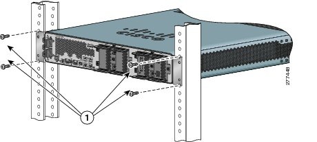
Mounting the Router in a Rack
After you attach the rack-mount brackets to the router chassis, use the screws provided with the rack to install the chassis in the rack. (See Figure 3-4.)
Tip
Caution
Figure 3-4 shows a typical installation in a rack.
Figure 3-4 Mounting the Chassis in a Rack (Typical)
Connecting Power
This section explains how to connect AC or DC power to Cisco 2010 CGR.
Warning
Connecting Power
To connect a power supply, follow these steps:
Step 1
Step 2
a.
b.
c.
d.
Note
e.
Caution
Warning
Figure 3-5 Connecting Power Using the Terminal Block
Step 3
Step 4
Figure 3-6 Using Tie Wraps with Strain Relief Mechanism
Caution
Caution
Caution
Caution
If you need a cable to connect to the low voltage DC power supply, cut off the plug from the power cord and hard wire the Cisco 2010 CGR low voltage DC input directly to its power source, observing the correct polarity markings.
Caution
Shutting Off Power
Even though shutting off power to the Cisco 2010 CGR is anticipated to be infrequent, there may be occasion to turn off the router. There is no on/off switch on the Cisco 2010 CGR. This ensures that there will not be any accidental shutdown due to turning off a power switch; thus, guaranteeing a high reliability in keeping the router up. To shut off power to the router, there are two options:
•
The power supplies on the Cisco 2010 CGR router are hot swappable, so merely removing them from the router will remove power from the router and shut it down.
•
A disconnect device must be located in the proximity of the Cisco 2010 CGR router and must be readily accessible. The disconnect device must also comply with IEC 60947-1 and IEC 60947-3 or an equivalent approved disconnect device appropriate for the country of installation and be identified as the disconnect device for this equipment.
Note
Connecting to a Console Terminal or Modem
The router has asynchronous serial ports and auxiliary ports. These ports provide administrative access to the router either locally (with a console terminal or a PC) or remotely (with a modem). To configure the router through the Cisco IOS command-line interface (CLI), you must establish a connection between the router console port and either a terminal or a PC.
Table 3-1 shows cables and adapters to establish a local or remote connection.
Table 3-1 Local and Remote Connections
Serial (RJ-45)
EIA RJ-45
Serial (USB)
USB 5-pin mini USB Type-B-to-USB Type-A
Auxiliary (Modem)
DB-9-to-DB-25
Connecting to the Serial Port with Microsoft Windows
This section describes using Microsoft Windows to connect to the serial port.
Note
Step 1
or
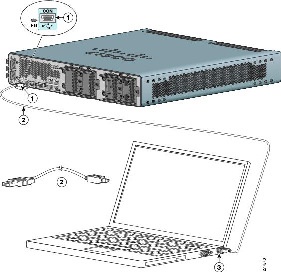
Connect a USB 5-pin mini USB Type-B to the USB console port, as shown in Figure 3-7. If you are using the USB serial port for the first time on a Windows-based PC, install the USB driver now according to the instructions in the following sections.•
•
•
Note
Step 2
Note
Step 3
•
•
•
•
•
Figure 3-7 Connecting the USB Console Cable to the Cisco 2010 CGR
1
USB 5-pin mini USB type-B console port
2
USB 5-pin mini USB type-B to USB type-A console cable
3
USB Type-A
Connecting to the Console Port with Mac OS X
This procedure describes how to connect a Mac OS X system USB port to the console using the built in OS X Terminal utility.
Step 1
Step 2
Step 3
macbook:user$ cd /devmacbook:user$ ls -ltr /dev/*usb*crw-rw-rw- 1 root wheel 9, 66 Apr 1 16:46 tty.usbmodem1a21 DT-macbook:dev user$Step 4
macbook:user$ screen /dev/tty.usbmodem1a21 9600To disconnect the OS X USB console from the Terminal window
Enter Ctrl-A followed by Ctrl-\
Connecting to the Console Port with Linux
This procedure shows how to connect a Linux system USB port to the console using the built in Linux Terminal utility.
Step 1
Step 2
Step 3
root@usb-suse# cd /devroot@usb-suse /dev# ls -ltr *ACM*crw-r--r-- 1 root root 188, 0 Jan 14 18:02 ttyACM0root@usb-suse /dev#Step 4
root@usb-suse /dev# screen /dev/ttyACM0 9600To disconnect the Linux USB console from the Terminal window
Enter Ctrl-A followed by :, then type quit
Installing the Cisco Microsoft Windows USB Device Driver
A USB device driver must be installed the first time a Microsoft Windows-based PC is connected to the USB serial port on the router.
This section contains the following topics:
•
•
•
Installing the Cisco Microsoft Windows XP USB Driver
This procedure shows how to install the Microsoft Windows XP USB driver.
Step 1
Step 2
Step 3
Step 4
Step 5
Step 6
Step 7
Installing the Cisco Microsoft Windows 2000 USB Driver
This procedure shows how to install the Microsoft Windows 2000 USB driver.
Step 1
Step 2
Step 3
Step 4
Step 5
Step 6
Step 7
Installing the Cisco Microsoft Windows Vista USB Driver
This procedure shows how to install the Microsoft Windows Vista USB driver.
Step 1
Step 2
Step 3
Step 4
Note
Step 5
Step 6
Step 7
Uninstalling the Cisco Microsoft Windows USB Driver
This section provides instructions for how to uninstall the Cisco Microsoft Windows USB device driver.
•
•
Uninstalling the Cisco Microsoft Windows XP and 2000 USB Driver
This procedure shows you how to uninstall both the Microsoft Windows XP and 2000 USB driver. The driver can be removed using the Windows Add or Remove Programs utility or the setup.exe program.
Using the Add Remove Programs utility
Note
Step 1
Step 2
Step 3
Using the Setup.exe program
Note
Step 1
Step 2
Step 3
Step 4
Step 5
Uninstalling the Cisco Microsoft Windows Vista USB Driver
This procedure shows you how to uninstall the Microsoft Windows Vista USB driver.
Note
Step 1
Step 2
Step 3
Step 4
Note
Step 5
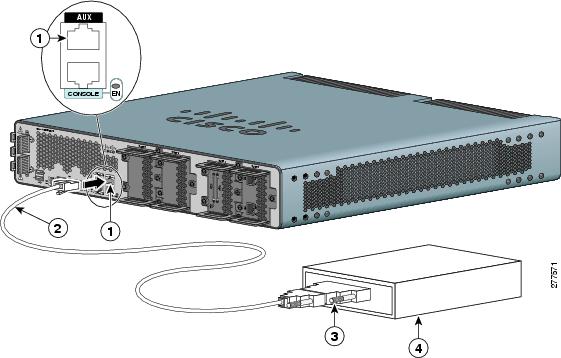
Connecting to the Auxiliary Port
When a modem is connected to the auxiliary port, a remote user can dial in to the router and configure it.
To connect a modem to the router, follow these steps:
Step 1
Figure 3-8 Connecting a Modem to the Cisco 2010 CGR
Step 2
Step 3
Step 4
Connecting WAN and LAN Interfaces
This section describes how to connect WAN and LAN interface cables.
Note
Warning
Warning
Warning
Ports and Cabling
Table 3-2 summarizes typical WAN and LAN connections for Cisco 2010 CGR routers. The connections summarized here are also described in detail in Cisco Modular Access Router Cable Specifications
Table 3-2 WAN, LAN, and Voice Connections
Ethernet
RJ-45, yellow
Ethernet hub or Ethernet switch
Category 5 or higher Ethernet
T1/E1 WAN
RJ-48C/CA81A
T1 or E1 network
RJ-48 T1/E12
Cisco serial
60-pin D-sub, blue
CSU/DSU and serial network or equipment
Cisco serial transition cable that matches the signaling protocol (EIA/TIA-232, V.35 or X.21
and the serial port operating mode (DTE or DCE).3Cisco Smart serial
Cisco Smart compact connector, blue
CSU/DSU and serial network or equipment
56/64-kbps DSU/CSU
8-pin modular, blue
RJ-48S interface in subrate device or network
RJ-48 straight-through
T1/FT1 DSU/CSU
8-pin modular, blue
RJ-48C interface
RJ-48 straight-through
Gigabit Ethernet SFP, optical
LC, color according to optical wavelength
1000BASE-SX, -LX, -ZX, 100BASE-FX and 100BASE-LX
Optical fiber as specified on applicable data sheet
Gigabit Ethernet SFP, copper
RJ-45
1000BASE-T
Category 5, 5e, 6 UTP
1 Cable color codes are specific to Cisco cables.
2 For T1/E1 interfaces, shielded cables are required to meet EN55022, Cispr 22, and EN300-386 compliance.
3 See Cisco Modular Access Router Cable Specifications for information about choosing these cables.
.
Connection Procedures and Precautions
To properly connect cables follow these steps:
Step 1
Step 2
Step 3
Step 4
Note
For cable pinouts, see Cisco Modular Access Router Cable Specifications on www.cisco.com.