- Preface
- Overview of the Hardware and Software
- Basic Router Configuration
- Configuring Ethernet CFM and Y.1731 Performance Monitoring on Layer 3 Interfaces
- Configuring Ethernet Virtual Connection Bridge Domain
- Configuring EtherChannel
- Configuring Backup Data Lines and Remote Management
- Configuring Power Efficiency Management
- Configuring Security Features
- Configuring Identity Features on Layer 3 Interface
- Unified Communications on Cisco Integrated Services Routers
- Configuring Next-Generation High-Density PVDM3 Modules
- Multi-Gigabit Fabric on the Router
- Upgrading the Cisco IOS Software
- Wireless Overview
- Configuring the Wireless Device
- Configuring the Radio
- Administering the Wireless Device
- Cisco IOS CLI for Initial Configuration
- Using CompactFlash Memory Cards
- Using ROM Monitor
- Changing the Configuration Register Settings
Cisco 3900 Series, 2900 Series, and 1900 Series Software Configuration Guide
Bias-Free Language
The documentation set for this product strives to use bias-free language. For the purposes of this documentation set, bias-free is defined as language that does not imply discrimination based on age, disability, gender, racial identity, ethnic identity, sexual orientation, socioeconomic status, and intersectionality. Exceptions may be present in the documentation due to language that is hardcoded in the user interfaces of the product software, language used based on RFP documentation, or language that is used by a referenced third-party product. Learn more about how Cisco is using Inclusive Language.
- Updated:
- July 25, 2014
Chapter: Configuring Security Features
- Configuring the Cryptographic Engine Accelerator
- Configuring SSL VPN
- Authentication, Authorization, and Accounting
- Configuring AutoSecure
- Configuring Access Lists
- Configuring Cisco IOS Firewall
- Zone-Based Policy Firewall
- Configuring Cisco IOS IPS
- Content Filtering
- Configuring VPN
Configuring Security Features
Cisco 3900 series, Cisco 2900 series, and Cisco 1900 series integrated services routers (ISRs) provide the following security features:
- Configuring the Cryptographic Engine Accelerator
- Configuring SSL VPN
- Authentication, Authorization, and Accounting
- Configuring AutoSecure
- Configuring Access Lists
- Configuring Cisco IOS Firewall
- Zone-Based Policy Firewall
- Configuring Cisco IOS IPS
- Content Filtering
- Configuring VPN
- Configuring Dynamic Multipoint VPN
- Configuring Group Encrypted Transport VPN
Configuring the Cryptographic Engine Accelerator
Services Performance Engine 200 and Services Performance Engine 250 have an onboard cryptographic engine accelerator that is shared between SSLVPN and IPSec protocols.
By default, acceleration of SSL is disabled so IPSec performance is maximized. To set up a router as an SSLVPN gateway, enable hardware acceleration for SSLVPN with the crypto engine accelerator bandwidth-allocation ssl fair command from global configuration mode. Issue the reload command.
Configuring SSL VPN
The Secure Socket Layer Virtual Private Network (SSL VPN) feature (also known as WebVPN) provides support, in Cisco IOS software, for remote user access to enterprise networks from anywhere on the Internet. Remote access is provided through a SSL–enabled SSL VPN gateway. The SSL VPN gateway allows remote users to establish a secure VPN tunnel using a web browser. This feature provides a comprehensive solution that allows easy access to a broad range of web resources and web-enabled applications using native HTTP over SSL (HTTPS) browser support. SSL VPN delivers three modes of SSL VPN access: clientless, thin-client, and full-tunnel client support.
For additional information about configuring SSL VPN, see the “ SSL VPN” section of Cisco IOS Security Configuration Guide: Secure Connectivity, Release 12.4T at: http://www.cisco.com/en/US/docs/ios/sec_secure_connectivity/configuration/guide/12_4t/
sec_secure_connectivity_12_4t_book.html.
Authentication, Authorization, and Accounting
Authentication, Authorization, and Accounting (AAA) network security services provide the primary framework through which you set up access control on your router. Authentication provides the method of identifying users, including login and password dialog, challenge and response, messaging support, and, depending on the security protocol you choose, encryption. Authorization provides the method for remote access control, including one-time authorization or authorization for each service, per-user account list and profile, user group support, and support of IP, Internetwork Packet Exchange (IPX), AppleTalk Remote Access (ARA), and Telnet. Accounting provides the method for collecting and sending security server information used for billing, auditing, and reporting, such as user identities, start and stop times, executed commands (such as PPP), number of packets, and number of bytes.
AAA uses protocols such as Remote Authentication Dial-In User Service (RADIUS), Terminal Access Controller Access Control System Plus (TACACS+), or Kerberos to administer its security functions. If your router is acting as a network access server, AAA is the means through which you establish communication between your network access server and your RADIUS, TACACS+, or Kerberos security server.
For information about configuring AAA services and supported security protocols, authentication authorization, accounting, RADIUS, TACACS+, or Kerberos, see the following sections of Cisco IOS Security Configuration Guide: Securing User Services, Release 12.4T at:
http://www.cisco.com/en/US/docs/ios/sec_user_services/configuration/guide/
Configuring AutoSecure
The AutoSecure feature disables common IP services that can be exploited for network attacks and enables IP services and features that can aid in the defense of a network when under attack. These IP services are all disabled and enabled simultaneously with a single command, greatly simplifying security configuration on your router. For a complete description of the AutoSecure feature, see the AutoSecure feature document at: http://www.cisco.com/univercd/cc/td/doc/product/software/ios123/123newft/123_1/ftatosec.htm.
Configuring Access Lists
Access lists permit or deny network traffic over an interface, based on source IP address, destination IP address, or protocol. Access lists are configured as standard or extended. A standard access list either permits or denies passage of packets from a designated source. An extended access list allows designation of both the destination and the source, and it allows designation of individual protocols to be permitted or denied passage.
For more complete information on creating access lists, see the “Access Control Lists” section of Cisco IOS Security Configuration Guide: Securing the Data Plane, Release 12.4T at: http://www.cisco.com/en/US/docs/ios/sec_data_plane/configuration/guide/12_4t/
sec_data_plane_12_4t_book.html.
An access list is a series of commands with a common tag to bind them together. The tag is either a number or a name. Table 1 lists the commands used to configure access lists.
To create, refine, and manage access lists, see the following sections of the “Access Control Lists” section of Cisco IOS Security Configuration Guide: Securing the Data Plane, Release 12.4T at:
http://www.cisco.com/en/US/docs/ios/sec_data_plane/configuration/guide/12_4t/
sec_data_plane_12_4t_book.html :
- Creating an IP Access List and Applying It to an Interface
- Creating an IP Access List to Filter IP Options, TCP Flags, Noncontiguous Ports, or TTL Values
- Refining an IP Access List
- Displaying and Clearing IP Access List Data Using ACL Manageability
Access Groups
An access group is a sequence of access list definitions bound together with a common name or number. An access group is enabled for an interface during interface configuration. Use the following guidelines when creating access groups:
- The order of access list definitions is significant. A packet is compared against the first access list in the sequence. If there is no match (that is, if neither a permit nor a deny occurs), the packet is compared with the next access list, and so on.
- All parameters must match the access list before the packet is permitted or denied.
- There is an implicit “deny all” at the end of all sequences.
For information on configuring and managing access groups, see the “Creating an IP Access List to Filter IP Options, TCP Flags, Noncontiguous Ports, or TTL Values” section of the “Access Control Lists” section of Cisco IOS Security Configuration Guide: Securing the Data Plane, Release 12.4T at: http://www.cisco.com/en/US/docs/ios/sec_data_plane/configuration/guide/12_4t/
sec_data_plane_12_4t_book.html .
Configuring Cisco IOS Firewall
The Cisco IOS Firewall lets you configure a stateful firewall where packets are inspected internally and the state of network connections is monitored. Stateful firewall is superior to static access lists because access lists can only permit or deny traffic based on individual packets, not based on streams of packets. Also, because the Cisco IOS Firewall inspects the packets, decisions to permit or deny traffic can be made by examining application layer data, which static access lists cannot examine.
To configure a Cisco IOS Firewall, specify which protocols to examine by using the following command in interface configuration mode:
ip inspect name inspection-name protocol timeout seconds
When inspection detects that the specified protocol is passing through the firewall, a dynamic access list is created to allow the passage of return traffic. The timeout parameter specifies the length of time that the dynamic access list remains active without return traffic passing through the router. When the timeout value is reached, the dynamic access list is removed, and subsequent packets (possibly valid ones) are not permitted.
Use the same inspection name in multiple statements to group them into one set of rules. This set of rules can be activated elsewhere in the configuration by using the ip inspect inspection-name { in | out } command when you configure an interface at the firewall.
For additional information about configuring a Cisco IOS Firewall, see “Cisco IOS Firewall Overview” at: http://www.cisco.com/en/US/docs/ios/security/configuration/guide/sec_ios_firewall_ov.html.
The Cisco IOS Firewall may also be configured to provide voice security in Session Initiated Protocol (SIP) applications. SIP inspection provides basic inspection functionality (SIP packet inspection and detection of pinhole openings), as well protocol conformance and application security. For more information, see “Cisco IOS Firewall: SIP Enhancements: ALG and AIC” at: http://www.cisco.com/en/US/docs/ios/security/configuration/guide/sec_sip_alg_aic.html.
Zone-Based Policy Firewall
The Cisco IOS Zone-Based Policy Firewall can be used to deploy security policies by assigning interfaces to different zones and configuring a policy to inspect the traffic moving between these zones. The policy specifies a set of actions to be applied on the defined traffic class.
For additional information about configuring zone-based policy firewall, see the “ Zone-Based Policy Firewall” section of Cisco IOS Security Configuration Guide: Securing the Data Plane, Release 12.4T at:
http://www.cisco.com/en/US/docs/ios/sec_data_plane/configuration/guide/12_4t/
sec_data_plane_12_4t_book.html .
Configuring Cisco IOS IPS
Cisco IOS Intrusion Prevention System (IPS) technology enhances perimeter firewall protection by taking appropriate action on packets and flows that violate the security policy or represent malicious network activity.
Cisco IOS IPS identifies attacks using “signatures” to detect patterns of misuse in network traffic. Cisco IOS IPS acts as an in-line intrusion detection sensor, watching packets and sessions as they flow through the router, scanning each to match currently active (loaded) attack signatures. When Cisco IOS IPS detects suspicious activity, it responds before network security can be compromised, it logs the event, and, depending on the action(s) configured to be taken for the detected signature(s), it does one of the following:
- Sends an alarm in syslog format or logs an alarm in Secure Device Event Exchange (SDEE) format
- Drops suspicious packets
- Resets the connection
- Denies traffic from the source IP address of the attacker for a specified amount of time
- Denies traffic on the connection for which the signature was seen for a specified amount of time
For additional information about configuring Cisco IOS IPS, see the “ Cisco IOS IPS 5.x Signature Format Support and Usability Enhancements” section of Cisco IOS Security Configuration Guide: Securing the Data Plane, Release 12.4T at: http://www.cisco.com/en/US/docs/ios/sec_data_plane/configuration/guide/12_4t/
sec_data_plane_12_4t_book.html.
Content Filtering
Cisco 3900 series, 2900 series, and 1900 series ISRs provide category-based URL filtering. The user provisions URL filtering on the ISR by selecting categories of websites to be permitted or blocked. An external server, maintained by a third party, is used to check for URLs in each category. Permit and deny policies are maintained on the ISR. The service is subscription based, and the URLs in each category are maintained by the third party vendor.
For additional information about configuring URL filtering, see “Subscription-based Cisco IOS Content Filtering” at: http://www.cisco.com/en/US/docs/ios/security/configuration/guide/sec_url_filtering.html.
Configuring VPN
A Virtual Private Network (VPN) connection provides a secure connection between two networks over a public network such as the Internet. Cisco 3900 series, 2900 series, and 1900 series ISRs support two types of VPNs: site-to-site and remote access. Remote access VPNs are used by remote clients to log in to a corporate network. Site-to-site VPNs connect branch offices to corporate offices. This section gives an example for each.
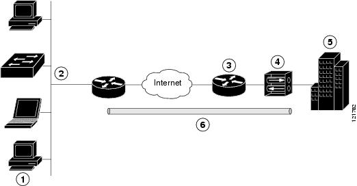
The configuration of a remote access VPN uses Cisco Easy VPN and an IP Security (IPSec) tunnel to configure and secure the connection between the remote client and the corporate network. Figure 1 shows a typical deployment scenario.
Figure 1 Remote Access VPN Using IPSec Tunnel
|
|
|
|
|
VPN client—Cisco 3900 series, 2900 series, or 1900 series ISR |
|
|
|
|
|
VPN server—Easy VPN server; for example, a Cisco VPN 3000 concentrator with outside interface address 210.110.101.1 |
|
|
|
|
|
The Cisco Easy VPN client feature eliminates much of the tedious configuration work by implementing the Cisco Unity Client protocol. This protocol allows most VPN parameters, such as internal IP addresses, internal subnet masks, DHCP server addresses, Windows Internet Naming Service (WINS) server addresses, and split-tunneling flags, to be defined at a VPN server, such as a Cisco VPN 3000 series concentrator that is acting as an IPSec server.
A Cisco Easy VPN server–enabled device can terminate VPN tunnels initiated by mobile and remote workers who are running Cisco Easy VPN Remote software on PCs. Cisco Easy VPN server–enabled devices allow remote routers to act as Cisco Easy VPN Remote nodes.
The Cisco Easy VPN client feature can be configured in one of two modes—client mode or network extension mode. Client mode is the default configuration and allows only devices at the client site to access resources at the central site. Resources at the client site are unavailable to the central site. Network extension mode allows users at the central site (where the Cisco VPN 3000 series concentrator is located) to access network resources on the client site.
After the IPSec server has been configured, a VPN connection can be created with minimal configuration on an IPSec client. When the IPSec client initiates the VPN tunnel connection, the IPSec server pushes the IPSec policies to the IPSec client and creates the corresponding VPN tunnel connection.

Note![]() The Cisco Easy VPN client feature supports configuration of only one destination peer. If your application requires creation of multiple VPN tunnels, you must manually configure the IPSec VPN and Network Address Translation/Peer Address Translation (NAT/PAT) parameters on both the client and the server.
The Cisco Easy VPN client feature supports configuration of only one destination peer. If your application requires creation of multiple VPN tunnels, you must manually configure the IPSec VPN and Network Address Translation/Peer Address Translation (NAT/PAT) parameters on both the client and the server.
Cisco 3900 series, 2900 series, and 1900 series ISRs can be also configured to act as Cisco Easy VPN servers, letting authorized Cisco Easy VPN clients establish dynamic VPN tunnels to the connected network. For information on configuring Cisco Easy VPN servers, see the Easy VPN Server feature at:
http://www.cisco.com/en/US/docs/ios/12_2t/12_2t8/feature/guide/ftunity.html.
The configuration of a site-to-site VPN uses IPSec and the generic routing encapsulation (GRE) protocol to secure the connection between the branch office and the corporate network. Figure 2 shows a typical deployment scenario.
Figure 2 Site-to-Site VPN Using an IPSec Tunnel and GRE
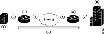
For more information about IPSec and GRE configuration, see the Configuring Security for VPNs with IPSec” chapter of Cisco IOS Security Configuration Guide: Secure Connectivity, Release 12.4T at:
http://www.cisco.com/en/US/docs/ios/sec_secure_connectivity/configuration/guide/12_4t/
sec_secure_connectivity_12_4t_book.html.
Each example configures a VPN over an IPSec tunnel, using the procedure given in the “Configure a VPN over an IPSec Tunnel” section. Then, the specific procedure for a remote access configuration is given, followed by the specific procedure for a site-to-site configuration.
The examples shown in this chapter apply only to the endpoint configuration on the Cisco 3900 series, 2900 series, and 1900 series ISRs. Any VPN connection requires both endpoints to be properly configured in order to function. See the software configuration documentation as needed to configure VPN for other router models.
VPN configuration information must be configured on both endpoints. You must specify parameters such as internal IP addresses, internal subnet masks, DHCP server addresses, and Network Address Translation (NAT).
- “Configure a VPN over an IPSec Tunnel” section
- “Create a Cisco Easy VPN Remote Configuration” section
- “Configure a Site-to-Site GRE Tunnel” section
Configure a VPN over an IPSec Tunnel
Perform the following tasks to configure a VPN over an IPSec tunnel:
Configure the IKE Policy
To configure the Internet Key Exchange (IKE) policy, follow these steps, beginning in global configuration mode.
SUMMARY STEPS
1.![]() crypto isakmp policy priority
crypto isakmp policy priority
2.![]() encryption { des | 3des | aes | aes 192 | aes 256}
encryption { des | 3des | aes | aes 192 | aes 256}
DETAILED STEPS
|
|
|
|
|---|---|---|
|
|
Creates an IKE policy that is used during IKE negotiation. The priority is a number from 1 to 10000, with 1 being the highest. Also enters the ISAKMP1 policy configuration mode. |
|
encryption { des | 3des | aes | aes 192 | aes 256} |
Specifies the encryption algorithm used in the IKE policy. The example specifies 168-bit DES2. |
|
|
|
Specifies the hash algorithm used in the IKE policy. The example specifies the MD53 algorithm. The default is SHA-14. |
|
authentication { rsa-sig | rsa-encr | pre-share } |
||
|
|
Specifies the Diffie-Hellman group to be used in an IKE policy. |
|
|
|
Specifies the lifetime, from 60 to 86400 seconds, for an IKE SA5. |
|
|
|
Exits IKE policy configuration mode and enters global configuration mode. |
|
1.ISAKMP = Internet Security Association Key and Management Protocol |
Configure Group Policy Information
To configure the group policy, follow these steps, beginning in global configuration mode.
SUMMARY STEPS
1.![]() crypto isakmp client configuration group { group-name | default }
crypto isakmp client configuration group { group-name | default }
6.![]() ip local pool { default | poolname } [ low-ip-address [ high-ip-address ]]
ip local pool { default | poolname } [ low-ip-address [ high-ip-address ]]
DETAILED STEPS
|
|
|
|
|---|---|---|
crypto isakmp client configuration group { group-name | default } Router(config)# crypto isakmp client configuration group rtr-remote |
Creates an IKE policy group containing attributes to be downloaded to the remote client. |
|
|
|
||
|
|
Specifies the primary DNS6 server for the group. You may also want to specify WINS7 servers for the group by using the wins command. |
|
|
|
||
|
|
Exits IKE group policy configuration mode and enters global configuration mode. |
|
ip local pool { default | poolname } [ low-ip-address [ high-ip-address ]] Router(config)# ip local pool dynpool 30.30.30.20 30.30.30.30 |
Specifies a local address pool for the group. For details about this command and additional parameters that can be set, see Cisco IOS Dial Technologies Command Reference. |
|
|
Apply Mode Configuration to the Crypto Map
To apply mode configuration to the crypto map, follow these steps, beginning in global configuration mode.
SUMMARY STEPS
1.![]() crypto map map-name isakmp authorization list list-name
crypto map map-name isakmp authorization list list-name
2.![]() crypto map tag client configuration address [ initiate | respond ]
crypto map tag client configuration address [ initiate | respond ]
DETAILED STEPS
Enable Policy Lookup
To enable policy lookup through AAA, follow these steps, beginning in global configuration mode.
SUMMARY STEPS
2.![]() aaa authentication login { default | list-name } method1 [ method2... ]
aaa authentication login { default | list-name } method1 [ method2... ]
3.![]() aaa authorization {network | exec | commands level | reverse-access | configuration } { default | list-name } [ method1 [ method2... ]]
aaa authorization {network | exec | commands level | reverse-access | configuration } { default | list-name } [ method1 [ method2... ]]
4.![]() username name {nopassword | password password | password encryption-type encrypted-password }
username name {nopassword | password password | password encryption-type encrypted-password }
DETAILED STEPS
|
|
|
|
|---|---|---|
|
|
||
aaa authentication login { default | list-name } method1 [ method2... ] |
Specifies AAA authentication of selected users at login, and specifies the method used. This example uses a local authentication database. You could also use a RADIUS server for this. For details, see Cisco IOS Security Configuration Guide: Securing User Services, Release 2.4T and Cisco IOS Security Command Reference. |
|
aaa authorization {network | exec | commands level | reverse-access | configuration } { default | list-name } [ method1 [ method2... ]] |
Specifies AAA authorization of all network-related service requests, including PPP, and specifies the method of authorization. This example uses a local authorization database. You could also use a RADIUS server for this. For details, see Cisco IOS Security Configuration Guide: Securing User Services, Release 2.4T and Cisco IOS Security Command Reference. |
|
username name {nopassword | password password | password encryption-type encrypted-password } |
Establishes a username-based authentication system. This example implements a username of username1 with an encrypted password of password1. |
Configure IPSec Transforms and Protocols
A transform set represents a certain combination of security protocols and algorithms. During IKE negotiation, the peers agree to use a particular transform set for protecting data flow.
During IKE negotiations, the peers search multiple transform sets for a transform that is the same at both peers. When a transform set is found that contains such a transform, it is selected and applied to the protected traffic as a part of both peers’ configurations.
To specify the IPSec transform set and protocols, follow these steps, beginning in global configuration mode.
SUMMARY STEPS
1.![]() crypto ipsec profile profile-name
crypto ipsec profile profile-name
2.![]() crypto ipsec transform-set transform-set-name
crypto ipsec transform-set transform-set-name
3.![]() crypto ipsec security-association lifetime { seconds seconds | kilobytes kilobytes }
crypto ipsec security-association lifetime { seconds seconds | kilobytes kilobytes }
DETAILED STEPS
|
|
|
|
|---|---|---|
crypto ipsec profile profile-name |
Configures an IPSec profile to apply protection on the tunnel for encryption. |
|
crypto ipsec transform-set transform-set-name transform1 [ transform2 ] [ transform3 ] [ transform4 ] Router(config)# crypto ipsec transform-set vpn1 esp-3des esp-sha-hmac |
Defines a transform set—an acceptable combination of IPSec security protocols and algorithms. See Cisco IOS Security Command Reference for detail about the valid transforms and combinations. |
|
crypto ipsec security-association lifetime { seconds seconds | kilobytes kilobytes } Router(config)# crypto ipsec security-association lifetime seconds 86400 |
Specifies global lifetime values used when IPSec security associations are negotiated. See Cisco IOS Security Command Reference for details. |
Configure the IPSec Crypto Method and Parameters
A dynamic crypto map policy processes negotiation requests for new security associations from remote IPSec peers, even if the router does not know all the crypto map parameters (for example, IP address).
To configure the IPSec crypto method, follow these steps, beginning in global configuration mode.
SUMMARY STEPS
1.![]() crypto dynamic-map dynamic-map-name dynamic-seq-num
crypto dynamic-map dynamic-map-name dynamic-seq-num
2.![]() set transform-set transform-set-name [ transform-set-name2...transform-set-name6 ]
set transform-set transform-set-name [ transform-set-name2...transform-set-name6 ]
5.![]() crypto map map-name seq-num [ ipsec-isakmp ] [ dynamic dynamic-map-name ] [ discover ] [ profile profile-name ]
crypto map map-name seq-num [ ipsec-isakmp ] [ dynamic dynamic-map-name ] [ discover ] [ profile profile-name ]
DETAILED STEPS
|
|
|
|
|---|---|---|
crypto dynamic-map dynamic-map-name dynamic-seq-num |
Creates a dynamic crypto map entry and enters crypto map configuration mode. See Cisco IOS Security Command Reference for more detail about this command. |
|
set transform-set transform-set-name [ transform-set-name2...transform-set-name6 ] |
Specifies which transform sets can be used with the crypto map entry. |
|
|
|
Creates source proxy information for the crypto map entry. See Cisco IOS Security Command Reference for details. |
|
|
|
||
crypto map map-name seq-num [ ipsec-isakmp ] [ dynamic dynamic-map-name ] [ discover ] [ profile profile-name ] Router(config)# crypto map static-map 1 ipsec-isakmp dynamic dynmap |
Apply the Crypto Map to the Physical Interface
The crypto maps must be applied to each interface through which IPSec traffic flows. Applying the crypto map to the physical interface instructs the router to evaluate all the traffic against the security associations database. With the default configurations, the router provides secure connectivity by encrypting the traffic sent between remote sites. However, the public interface still allows the rest of the traffic to pass and provides connectivity to the Internet.
To apply a crypto map to an interface, follow these steps, beginning in global configuration mode.
SUMMARY STEPS
DETAILED STEPS
|
|
|
|
|---|---|---|
|
|
Enters the interface configuration mode for the interface to which you are applying the crypto map. |
|
|
|
Applies the crypto map to the interface. See Cisco IOS Security Command Reference for more detail about this command. |
|
|
|
Where to Go Next
If you are creating a Cisco Easy VPN remote configuration, go to the “Create a Cisco Easy VPN Remote Configuration” section.
If you are creating a site-to-site VPN using IPSec tunnels and GRE, go to the “Configure a Site-to-Site GRE Tunnel” section.
Create a Cisco Easy VPN Remote Configuration
The router that is acting as the Cisco Easy VPN client must create a Cisco Easy VPN remote configuration and assign it to the outgoing interface.
To create the remote configuration, follow these steps, beginning in global configuration mode.
SUMMARY STEPS
1.![]() crypto ipsec client ezvpn name
crypto ipsec client ezvpn name
2.![]() group group-name key group-key
group group-name key group-key
3.![]() peer { ipaddress | hostname }
peer { ipaddress | hostname }
4.![]() mode { client | network-extension | network extension plus }
mode { client | network-extension | network extension plus }
6.![]() crypto isakmp keepalive seconds
crypto isakmp keepalive seconds
DETAILED STEPS
|
|
|
|
|---|---|---|
crypto ipsec client ezvpn name |
Creates a Cisco Easy VPN remote configuration, and enters Cisco Easy VPN remote configuration mode. |
|
group group-name key group-key Router(config-crypto-ezvpn)# group ezvpnclient key secret-password |
Specifies the IPSec group and IPSec key value for the VPN connection. |
|
Specifies the peer IP address or hostname for the VPN connection. Note A hostname can be specified only when the router has a DNS server available for hostname resolution. Note Use this command to configure multiple peers for use as backup. If one peer goes down, the Easy VPN tunnel is established with the second available peer. When the primary peer comes up again, the tunnel is reestablished with the primary peer. |
||
mode { client | network-extension | network extension plus } |
||
|
|
||
crypto isakmp keepalive seconds |
Enables dead peer detection messages. Time between messages is given in seconds, with a range of 10 to 3600. |
|
|
|
Enters the interface configuration mode for the interface to which you are applying the Cisco Easy VPN remote configuration. Note For routers with an ATM WAN interface, this command would be interface atm 0. |
|
crypto ipsec client ezvpn name [ outside | inside ] Router(config-if)# crypto ipsec client ezvpn ezvpnclient outside |
Assigns the Cisco Easy VPN remote configuration to the WAN interface which causes the router to automatically create the NAT or PAT8 and the access list configuration needed for the VPN connection. |
|
|
|
|
|
Configuration Example
The following configuration example shows a portion of the configuration file for the VPN and IPSec tunnel described in this chapter.
Configure a Site-to-Site GRE Tunnel
To configure a site-to-site GRE tunnel, follow these steps, beginning in global configuration mode.
SUMMARY STEPS
3.![]() tunnel source interface-type number
tunnel source interface-type number
4.![]() tunnel destination default-gateway-ip-address
tunnel destination default-gateway-ip-address
7.![]() ip access-list { standard | extended } access-list-name
ip access-list { standard | extended } access-list-name
8.![]() permit protocol source source-wildcard destination destination-wildcard
permit protocol source source-wildcard destination destination-wildcard
DETAILED STEPS
|
|
|
|
|---|---|---|
|
|
Creates a tunnel interface and enters interface configuration mode. |
|
|
|
||
tunnel source interface-type number |
Specifies the source endpoint of the router for the GRE tunnel. |
|
tunnel destination default-gateway-ip-address |
Specifies the destination endpoint of the router for the GRE tunnel. |
|
|
|
Assigns a crypto map to the tunnel. Note Dynamic routing or static routes to the tunnel interface must be configured to establish connectivity between the sites. See Cisco IOS Security Configuration Guide: Secure Connectivity, Release 12.4T for details. |
|
|
|
Exits interface configuration mode and returns to global configuration mode. |
|
ip access-list { standard | extended } access-list-name |
Enters ACL9 configuration mode for the named ACL that the crypto map uses. |
|
permit protocol source source-wildcard destination destination-wildcard Router(config-acl)# permit gre host 192.168.100.1 host 192.168.101.1 |
Specifies that only GRE traffic is permitted on the outbound interface. |
|
|
|
|
|
Configuration Example
The following configuration example shows a portion of the configuration file for a site-to-site VPN using a GRE tunnel as described in the preceding sections.
Configuring Dynamic Multipoint VPN
The Dynamic Multipoint VPN (DMVPN) feature allows users to better scale large and small IP Security (IPsec) VPNs by combining GRE tunnels, IPsec encryption, and Next Hop Resolution Protocol (NHRP).
For additional information about configuring DMVPN, see the “Dynamic Multipoint VPN” section of Cisco IOS Security Configuration Guide: Secure Connectivity, Release 12.4T at:
http://www.cisco.com/en/US/docs/ios/sec_secure_connectivity/configuration/guide/12_4t/
sec_secure_connectivity_12_4t_book.html.
Configuring Group Encrypted Transport VPN
Group Encrypted Transport (GET) VPN is a set of features that are necessary to secure IP multicast group traffic or unicast traffic over a private WAN that originates on or flows through a Cisco IOS device. GET VPN combines the keying protocol Group Domain of Interpretation (GDOI) with IPsec encryption to provide users with an efficient method of securing IP multicast traffic or unicast traffic. GET VPN enables the router to apply encryption to nontunneled (that is, “native”) IP multicast and unicast packets and eliminates the requirement to configure tunnels to protect multicast and unicast traffic.
By removing the need for point-to-point tunnels, meshed networks can scale higher while maintaining network-intelligence features that are critical to voice and video quality, such as QoS, routing, and multicast. GET VPN offers a new standards-based IP security (IPsec) security model that is based on the concept of “trusted” group members. Trusted member routers use a common security methodology that is independent of any point-to-point IPsec tunnel relationship.
For additional information about configuring GET VPN, see Cisco Group Encrypted Transport VPN at:
http://www.cisco.com/en/US/docs/ios/12_4t/12_4t11/htgetvpn.html.
SGT over Ethernet Tagging
Cisco TrustSec (CTS) is an end-to-end network infrastructure that provides a scalable architecture for enforcement of role-based access control, identity-aware networking, and data confidentiality that helps to secure the network and its resources. CTS works by identifying and authenticating each network user and resource and assigning a 16-bit number called Security Group Tag (SGT). SGT is then propagated between network hops to allow intermediary devices (switches and routers) to enforce policies based on the identity tag.
CTS-capable devices have built-in hardware capabilities than can send and receive packets with SGT embedded in the MAC (L2) layer. This feature is called L2-SGT imposition. This allows Ethernet interfaces on the device to be enabled for L2-SGT imposition to enable the device to insert an SGT in the packet that is to be carried to its next- hop Ethernet neighbor. SGT over Ethernet Tagging is a type of hop-by-hop propagation of SGTs embedded in clear-text (unencrypted) Ethernet packets.
Restrictions for SGT over Ethernet Tagging
Configuring SGT over Ethernet Tagging
SUMMARY STEPS
3.![]() interface gigabitethernet slot / port
interface gigabitethernet slot / port
DETAILED STEPS
Example: Configuring SGT over Ethernet Tagging
This example shows how to configure SGT over Ethernet tagging with CTS SGT propagation enabled:
This example shows how to configure SGT over Ethernet tagging with CTS SGT propagation disabled:
Verifying SGT over Ethernet Tagging
Use the show cts interface brief command to display the CTS interface- specific configuration:
Use the s how cts platform interface interface-name stats detail command to display platform-specific CTS-related statistics:
 Feedback