Feedback Feedback
|
Table Of Contents
Cisco 1- and 2-port T1/E1 Multiflex Voice/WAN Interface Cards for the Cisco 1721 Router
Software Configuration Information
1- and 2-Port Multiflex Interface Cards
T1/E1 Data Configuration Examples
Verifying a Serial Interface Configuration
T1/E1 Drop-and-Insert Configuration
Drop-and-Insert Configuration Example
Verifying Drop-and-Insert Configuration
E1 G.703 Unstructured Configuration
E1 G.703 Configuration Example
Verifying Serial Interface Configuration
Cisco Product Security Overview
Reporting Security Problems in Cisco Products
Obtaining Technical Assistance
Cisco Technical Support Website
Definitions of Service Request Severity
Obtaining Additional Publications and Information
Cisco 1- and 2-port T1/E1 Multiflex Voice/WAN Interface Cards for the Cisco 1721 Router
The Cisco 1- and 2-port T1/E1 multiflex interface cards support generic single- or dual-port T1 or E1 trunk interfaces for voice, data, and integrated voice/data applications. These cards provide basic structured T1 service, as well as structured and unstructured E1 services.
On the Cisco 1721 router, these cards can be used as trunk interfaces for data services only, such as fractional n x 64-Kbps service for WANs (Frame Relay or leased line).
Table 1 describes and names each T1/E1 card that can be used in the Cisco 1721 router.
Related Documentation
This document provides updated information on Cisco 1- and 2-port T1/E1 multiflex interface cards. This information supplements the Cisco Interface Cards Hardware Installation Guide.
Use this document with the following guides:
•
Cisco 1700 Router Hardware Installation Guide
•
•
•
•
The platform documents are available at the following URL:
http://www.cisco.com/univercd/cc/td/doc/product/access/acs_mod/1700/index.htm
The IOS documents are available at the following URL:
http://www.cisco.com/univercd/cc/td/doc/product/software/ios122/
Software Configuration Information
This section provides pointers to information that is useful for configuring the interface card.
•
WAN Data Traffic Configuration on Digital T1/E1 Packet Voice Trunk Network Modules
Configuring T1/E1 High Capacity Digital Voice Port Adapters
•
G.703 Configuration for Multiflex Voice/WAN Interface Cards on Cisco 2600 and 3600 Series Routers
http://www.cisco.com/univercd/cc/td/doc/product/software/ios121/121newft/121t/121t1/dtg703.htm
•
T1/E1 Multiflex VWIC Enhancements
•
Configuring Digital T1 Packet Voice Trunk Network Modules on Cisco 2600 and Cisco 3600 Series Routers
/en/US/docs/ios/12_0t/12_0t7/feature/guide/t1_vo_t6.html
Configuring 1- and 2-Port T1/E1 Multiflex Voice/WAN Interface Cards on Cisco 2600 and 3600 Series Routers
/en/US/docs/ios/12_0/12_0x/feature/guide/t1_mf_xk.html
1- and 2-Port Multiflex Interface Cards
On the Cisco 1721 router, Cisco 1- and 2-port T1/E1 multiflex interface cards provide data access to the Public Switched Telephone Network (PSTN) domain through time-division multiplexing (TDM) ports.
Descriptions and connection information for Cisco 1-port multiflex interface cards are available at the following URL:
/en/US/docs/routers/access/1700/software/feature/guide/t1e11700.html#wp49314
Descriptions and connection information for Cisco 2-port multiflex interface cards are available at the following URL:
/en/US/docs/routers/access/1700/software/feature/guide/t1e11700.html#wp49419
T1/E1 Data Configuration
Follow these steps to configure your digital T1/E1 voice WAN interface card (VWIC) for WAN data traffic.
T1/E1 Data Configuration Examples
This section shows an example of a digital T1/E1 VWIC configured for Frame Relay to send WAN data traffic.
The channel-group 0 command is configured in such a way that the service provider can send Frame Relay link management information (LMI) on the T1 or E1 controller for Frame Relay data services. This command automatically creates serial interface 0:0.
All the WAN and Layer 3 protocol details are configured in the interface Serial 0:0 command. In the example below, Frame Relay encapsulation and IP address assignments are configured in interface Serial 0:0 commands.
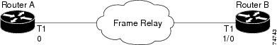
Figure 1 shows a diagram for the configuration example.
Figure 1 Configuration Example for T1/E1 WAN
T1 Configuration Example
This section shows a T1 configuration example for Router A, a Cisco 1721 router. (See Figure 1.)
card type t1controller T1 0framing esfclock source internallinecode b8zschannel-group 0 timeslots 1-24!interface Serial 0:0no ip addressencapsulation frame-relayno keepalive!interface Serial 0:0.1 point-to-pointip address 209.165.200.252 255.255.255.224frame-relay interface-dlci 100!interface FastEthernet0/0ip address 209.165.200.250 255.255.255.224!router eigrp 1network 209.165.200.224This section shows a T1 configuration example for Router B, a Cisco 3600 series router. (See Figure 1.)
controller T1 1/0framing esflinecode b8zschannel-group 0 timeslots 1-24 speed 64!interface Serial 1/0:0no ip addressencapsulation frame-relayno keepalive!interface Serial 1/0:0.1 point-to-pointip address 209.165.200.253 255.255.255.224frame-relay interface-dlci 100!interface FastEthernet0/0ip address 209.165.201.1 255.255.255.224!router eigrp 1network 209.165.200.224network 209.165.201.0E1 Configuration Example
This section shows an E1 configuration example for Router A, a Cisco 1721 router. (See Figure 1.)
card type e1controller E1 0framing crc4clock source internallinecode hdb3channel-group 0 timeslots 1-31!interface Serial 0:0no ip addressencapsulation frame-relayno keepalive!interface Serial 0:0.1 point-to-pointip address 209.165.200.252 255.255.255.224frame-relay interface-dlci 100!interface FastEthernet0/0ip address 209.165.200.250 255.255.255.224!router eigrp 1network 209.165.200.224This section shows an E1 configuration example for Router B, a Cisco 3600 series router. (See Figure 1.)
controller E1 1/0framing crc4linecode hdb3channel-group 0 timeslots 1-31!interface Serial 1/0:0no ip addressencapsulation frame-relayno keepalive!interface Serial 1/0:0.1 point-to-pointip address 209.165.200.253 255.255.255.224frame-relay interface-dlci 100!interface FastEthernet0/0ip address 209.165.201.1 255.255.255.224!router eigrp 1network 209.165.200.224network 209.165.201.0Verifying Controller Settings
The show controller t1/e1 command displays the status of T1 or E1 controllers, clock sources, and other settings for the ports. See the following examples for a T1 controller and an E1 controller, respectively.
Router#show controller t1 0T1 0 is up.Applique type is Channelized T1Cablelength is long gain36 0dbNo alarms detected.alarm-trigger is not setVersion info Firmware: 20011109, FPGA: 15Framing is ESF, Line Code is B8ZS, Clock Source is Internal.Data in current interval (130 seconds elapsed):0 Line Code Violations, 0 Path Code Violations0 Slip Secs, 0 Fr Loss Secs, 0 Line Err Secs, 0 Degraded Mins0 Errored Secs, 0 Bursty Err Secs, 0 Severely Err Secs, 0 Unavail SecsRouter#show controller e1 0E1 0 is up.Applique type is Channelized E1 - balancedNo alarms detected.alarm-trigger is not setVersion info Firmware: 20011109, FPGA: 15Framing is CRC4, Line Code is HDB3, Clock Source is Internal.Data in current interval (17 seconds elapsed):0 Line Code Violations, 0 Path Code Violations0 Slip Secs, 0 Fr Loss Secs, 0 Line Err Secs, 0 Degraded Mins0 Errored Secs, 0 Bursty Err Secs, 0 Severely Err Secs, 0 Unavail SecsVerifying a Serial Interface Configuration
To verify serial interface configuration, enter the show interfaces serial command. This command shows the status of all serial interfaces or of a specific serial interface. You can use this command to check the bandwidth, encapsulation, IP addressing, and other settings.
This example shows the verification of a T1 interface.
Router#show interfaces serial0:0Serial0:0 is up, line protocol is upHardware is DSX1MTU 1500 bytes, BW 1536 Kbit, DLY 20000 usec,reliability 255/255, txload 1/255, rxload 1/255Encapsulation HDLC, loopback not setKeepalive set (10 sec)FR SVC disabled, LAPF state downBroadcast queue 0/64, broadcasts sent/dropped 1/0, interface broadcasts 0Last input 00:00:37, output 00:00:19, output hang neverLast clearing of "show interface" counters 00:00:47Input queue: 0/75/0/0 (size/max/drops/flushes); Total output drops: 0Queueing strategy: weighted fairOutput queue: 0/1000/64/0 (size/max total/threshold/drops)Conversations 0/1/256 (active/max active/max total)Reserved Conversations 0/0 (allocated/max allocated)Available Bandwidth 1152 kilobits/sec5 minute input rate 0 bits/sec, 0 packets/sec5 minute output rate 0 bits/sec, 0 packets/sec1 packets input, 314 bytes, 0 no bufferReceived 0 broadcasts, 0 runts, 0 giants, 0 throttles0 input errors, 0 CRC, 0 frame, 0 overrun, 0 ignored, 0 abort1 packets output, 328 bytes, 0 underruns0 output errors, 0 collisions, 0 interface resets0 output buffer failures, 0 output buffers swapped out0 carrier transitionsThis example shows the verification of an E1 interface.
Router#show interfaces serial 0:0Serial0:0 is up, line protocol is upHardware is DSX1MTU 1500 bytes, BW 1984 Kbit, DLY 20000 usec,reliability 255/255, txload 1/255, rxload 1/255Encapsulation HDLC, loopback not setKeepalive set (10 sec)Last input 00:00:04, output 00:00:08, output hang neverLast clearing of "show interface" counters 00:00:08Input queue: 0/75/0/0 (size/max/drops/flushes); Total output drops: 0Queueing strategy: weighted fairOutput queue: 0/1000/64/0 (size/max total/threshold/drops)Conversations 0/1/256 (active/max active/max total)Reserved Conversations 0/0 (allocated/max allocated)Available Bandwidth 1488 kilobits/sec5 minute input rate 0 bits/sec, 0 packets/sec5 minute output rate 0 bits/sec, 0 packets/sec1 packets input, 24 bytes, 0 no bufferReceived 1 broadcasts, 0 runts, 0 giants, 0 throttles0 input errors, 0 CRC, 0 frame, 0 overrun, 0 ignored, 0 abort0 packets output, 0 bytes, 0 underruns0 output errors, 0 collisions, 0 interface resets0 output buffer failures, 0 output buffers swapped out0 carrier transitionsT1/E1 Drop-and-Insert Configuration
T1/E1 VWICs with drop-and-insert functionality connect other devices to a T1 or E1 data stream. Drop-and-insert technology is sometimes called TDM cross-connect.
Note
The following steps configure your T1/E1 VWIC for drop-and-insert capability. Repeat the procedure for each controller.
Step 1
Router#configure terminal
Enters global configuration mode. Skip this step if you are already in terminal configuration mode.
Step 2
Router(config)# card type {t1 | e1} subslot
Sets or changes the card type to support either T1 (t1) or E1 (e1) circuits.
•
•
•
Step 3
Router(config)#controller {T1 | E1} port
Enters controller configuration mode for a T1 or E1 controller at the port location specified. Skip this step if you are already in controller configuration mode.
Step 4
Router(config-controller)#framing {esf | sf}
or
Router(config-controller)#framing {crc4 | no-crc4}
Specifies the framing type designated by your service provider. Extended Superframe (ESF) and Super Frame (SF) are for T1 circuits, whereas cyclic redundancy check 4 (CRC4) and NO-CRC4 are for E1 circuits.
The default setting for T1 framing is esf. The default setting for E1 framing is crc4.
Note
Step 5
Router(config-controller)# clock source {line [primary | bits] | internal} [independent]
Specifies the clock source:
•
–
–
–
–
•
–
Note
router(config-controller)#channel-group 2
timeslots 3
%Channel-group already created.%Only 1 channel-group can be configured with independent clocking.%Insufficient resources to create channel groupWhen configuring between clock source independent and no clock source independent, the channel-group has to be removed.
Step 6
Router(config-controller)#linecode {ami | b8zs}
or
Router(config-controller)#linecode hdb3
Specifies the line code type designated by your service provider.
Alternate mark inversion (AMI) is used on older T1 circuits and references signal transitions with a binary 1, or mark. Binary 8 zero substitution (B8ZS), a more reliable method, is more popular. B8ZS encodes a sequence of eight zeros in a unique binary sequence to detect line-coding violations.
The default setting for T1 line code is b8zs.
High density binary 3 (HDB3) is used on E1 circuits.
Step 7
Router(config-controller)# tdm-group tdm-group-no timeslots timeslot-list
Used only when you need TDM groups for the drop-and-insert (also called TDM cross-connect) function with a 2-port T1/E1 trunk multiflex interface card.
The tdm-group-no parameter is a value from 0 to 23 for T1, and is a value from 0 to 30 for E1.
The timeslot-list parameter can be a single number, numbers separated by commas, or a pair of numbers separated by a hyphen that indicate a range of time slots. For T1, allowable values are from 1 to 24. For E1, allowable values are from 1 to 31.
The number of time slots must be the same on both ports in order for them to be cross-connected.
Note
Step 8
Router(config-controller)#no shutdown
Activates the controller.
Step 9
Router(config-controller)#exit
Exits controller configuration mode.
Step 10
Router(config)#connect id {T1 | E1} port tdm-group-no-1 {T1 | E1} port tdm-group-no-2
This global configuration command sets up the connection between two T1/E1 TDM groups.
The id parameter is a name for the connection.
The tdm-group-no-1 and tdm-group-no-2 parameters identify the TDM group numbers (from 0 to 31) on the specified controller. (These groups were set up in Step 7.)
Note
Step 11
Router(config-tdm-conn)#end
Exits to privileged EXEC mode.
Drop-and-Insert Configuration Example
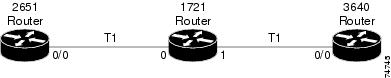
This section shows a sample configuration of a T1 drop-and-insert VWIC that provides a data connection between a Cisco 2651 router and a Cisco 3640 router, using T1. Figure 2 shows a diagram of the example.
Figure 2 Configuration Example for Drop-and-Insert
The following is the configuration for the Cisco 1721 router in Figure 2:
card type t1controller T1 0framing esflinecode b8zstdm-group 2 timeslots 13-24!controller T1 1framing esfclock source internallinecode b8zstdm-group 3 timeslots 1-12!connect dfw1 T1 0 2 T1 1 3The following shows a configuration for the Cisco 2651 router in Figure 2:
controller T1 0/0framing esfclock source internallinecode b8zschannel-group 0 timeslots 13-24!interface Serial 0/0:0ip address 209.165.200.253 255.255.255.224The following shows a configuration for the Cisco 3640 router in Figure 2:
controller T1 0/0framing esflinecode b8zschannel-group 2 timeslots 1-12!interface Serial 0/0:0ip address 209.165.200.252 255.255.255.224Please note the following:
•
•
•
Verifying Controller Settings
The show controller t1/e1 command displays the status of T1 or E1 controllers and displays information about clock sources for the ports:
Router#show controller t1T1 0 is up.Applique type is Channelized T1Cablelength is long gain36 0dbNo alarms detected.alarm-trigger is not setVersion info Firmware: 20011109, FPGA: 15Framing is ESF, Line Code is B8ZS, Clock Source is Line.Data in current interval (708 seconds elapsed):0 Line Code Violations, 0 Path Code Violations0 Slip Secs, 0 Fr Loss Secs, 0 Line Err Secs, 0 Degraded Mins0 Errored Secs, 0 Bursty Err Secs, 0 Severely Err Secs, 0 Unavail SecsT1 1 is up.Applique type is Channelized T1Cablelength is long gain36 0dbNo alarms detected.alarm-trigger is not setVersion info Firmware: 20011109, FPGA: 15Framing is ESF, Line Code is B8ZS, Clock Source is Internal.Data in current interval (708 seconds elapsed):0 Line Code Violations, 0 Path Code Violations0 Slip Secs, 0 Fr Loss Secs, 0 Line Err Secs, 0 Degraded Mins0 Errored Secs, 0 Bursty Err Secs, 0 Severely Err Secs, 0 Unavail SecsVerifying Drop-and-Insert Configuration
To verify drop-and-insert configuration, enter the show connection all command.
Router#show connection allID Name Segment 1 Segment 2 State============================================1 dfw1 T1 0 02 T1 1 03 UPE1 G.703 Unstructured Configuration
The following steps configure your E1 G.703 VWIC for unstructured G.703 capability.
For detailed information about configuring unstructured service for E1 networks, see the G.703 Configuration for Multiflex Voice/WAN Interface Cards on Cisco 2600 and 3600 Series Routers online document.
Repeat the following procedure for each E1 controller.
E1 G.703 Configuration Example
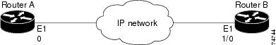
Figure 3 shows a diagram for the sample E1 G.703 configuration.
Figure 3 Configuration Example: E1 G.703
The following is the configuration for Router A, a Cisco 1721 router.
card type e1controller E1 0clock source internalchannel-group 0 unframed!interface Serial 0:0ip address 209.165.200.252 255.255.255.224The following is the configuration for Router B, a Cisco 3600 series router:
controller E1 1/0channel-group 0 unframed!interface Serial 1/0:0ip address 209.165.200.253 255.255.255.224Verifying Controller Settings
The show controller e1 command displays the status of E1 controllers and displays information about clock sources for the ports:
Router#show controller e1 0E1 0 is up.Applique type is Channelized E1 - balancedNo alarms detected.alarm-trigger is not setVersion info Firmware: 20011109, FPGA: 15Framing is UNFRAMED, Line Code is HDB3, Clock Source is Internal.Data in current interval (48 seconds elapsed):0 Line Code Violations, 0 Path Code Violations0 Slip Secs, 0 Fr Loss Secs, 0 Line Err Secs, 0 Degraded Mins0 Errored Secs, 0 Bursty Err Secs, 0 Severely Err Secs, 0 Unavail SecsVerifying Serial Interface Configuration
To verify serial interface configuration, enter the show interfaces serial command, which shows the status of all serial interfaces or the status of a specific serial interface. You can use this command to check the encapsulation, IP addressing, and other parameters:
Router#show interfaces serial0:0Serial0:0 is up, line protocol is upHardware is DSX1Internet address is 209.165.200.252/27MTU 1500 bytes, BW 2048 Kbit, DLY 20000 usec,reliability 255/255, txload 1/255, rxload 1/255Encapsulation HDLC, loopback not setKeepalive set (10 sec)Last input 00:00:01, output 00:00:03, output hang neverLast clearing of "show interface" counters 00:00:25Input queue: 0/75/0/0 (size/max/drops/flushes); Total output drops: 0Queueing strategy: weighted fairOutput queue: 0/1000/64/0 (size/max total/threshold/drops)Conversations 0/1/256 (active/max active/max total)Reserved Conversations 0/0 (allocated/max allocated)Available Bandwidth 1536 kilobits/sec5 minute input rate 0 bits/sec, 0 packets/sec5 minute output rate 0 bits/sec, 0 packets/sec1 packets input, 24 bytes, 0 no bufferReceived 1 broadcasts, 0 runts, 0 giants, 0 throttles0 input errors, 0 CRC, 0 frame, 0 overrun, 0 ignored, 0 abort1 packets output, 24 bytes, 0 underruns0 output errors, 0 collisions, 0 interface resets0 output buffer failures, 0 output buffers swapped out0 carrier transitionsObtaining Documentation
Cisco documentation and additional literature are available on Cisco.com. Cisco also provides several ways to obtain technical assistance and other technical resources. These sections explain how to obtain technical information from Cisco Systems.
Cisco.com
You can access the most current Cisco documentation at this URL:
http://www.cisco.com/univercd/home/home.htm
You can access the Cisco website at this URL:
You can access international Cisco websites at this URL:
http://www.cisco.com/public/countries_languages.shtml
Documentation DVD
Cisco documentation and additional literature are available in a Documentation DVD package, which may have shipped with your product. The Documentation DVD is updated regularly and may be more current than printed documentation. The Documentation DVD package is available as a single unit.
Registered Cisco.com users (Cisco direct customers) can order a Cisco Documentation DVD (product number DOC-DOCDVD=) from the Ordering tool or Cisco Marketplace.
Cisco Ordering tool:
http://www.cisco.com/en/US/partner/ordering/
Cisco Marketplace:
http://www.cisco.com/go/marketplace/
Ordering Documentation
You can find instructions for ordering documentation at this URL:
http://www.cisco.com/univercd/cc/td/doc/es_inpck/pdi.htm
You can order Cisco documentation in these ways:
•
http://www.cisco.com/en/US/partner/ordering/
•
Documentation Feedback
You can send comments about technical documentation to bug-doc@cisco.com.
You can submit comments by using the response card (if present) behind the front cover of your document or by writing to the following address:
Cisco Systems
Attn: Customer Document Ordering
170 West Tasman Drive
San Jose, CA 95134-9883We appreciate your comments.
Cisco Product Security Overview
Cisco provides a free online Security Vulnerability Policy portal at this URL:
http://www.cisco.com/en/US/products/products_security_vulnerability_policy.html
From this site, you can perform these tasks:
•
•
•
A current list of security advisories and notices for Cisco products is available at this URL:
If you prefer to see advisories and notices as they are updated in real time, you can access a Product Security Incident Response Team Really Simple Syndication (PSIRT RSS) feed from this URL:
http://www.cisco.com/en/US/products/products_psirt_rss_feed.html
Reporting Security Problems in Cisco Products
Cisco is committed to delivering secure products. We test our products internally before we release them, and we strive to correct all vulnerabilities quickly. If you think that you might have identified a vulnerability in a Cisco product, contact PSIRT:
•
•
Tip
Never use a revoked or an expired encryption key. The correct public key to use in your correspondence with PSIRT is the one that has the most recent creation date in this public key server list:
http://pgp.mit.edu:11371/pks/lookup?search=psirt%40cisco.com&op=index&exact=on
In an emergency, you can also reach PSIRT by telephone:
•
•
Obtaining Technical Assistance
For all customers, partners, resellers, and distributors who hold valid Cisco service contracts, Cisco Technical Support provides 24-hour-a-day, award-winning technical assistance. The Cisco Technical Support Website on Cisco.com features extensive online support resources. In addition, Cisco Technical Assistance Center (TAC) engineers provide telephone support. If you do not hold a valid Cisco service contract, contact your reseller.
Cisco Technical Support Website
The Cisco Technical Support Website provides online documents and tools for troubleshooting and resolving technical issues with Cisco products and technologies. The website is available 24 hours a day, 365 days a year, at this URL:
http://www.cisco.com/techsupport
Access to all tools on the Cisco Technical Support Website requires a Cisco.com user ID and password. If you have a valid service contract but do not have a user ID or password, you can register at this URL:
http://tools.cisco.com/RPF/register/register.do
Note
Submitting a Service Request
Using the online TAC Service Request Tool is the fastest way to open S3 and S4 service requests. (S3 and S4 service requests are those in which your network is minimally impaired or for which you require product information.) After you describe your situation, the TAC Service Request Tool provides recommended solutions. If your issue is not resolved using the recommended resources, your service request is assigned to a Cisco TAC engineer. The TAC Service Request Tool is located at this URL:
http://www.cisco.com/techsupport/servicerequest
For S1 or S2 service requests or if you do not have Internet access, contact the Cisco TAC by telephone. (S1 or S2 service requests are those in which your production network is down or severely degraded.) Cisco TAC engineers are assigned immediately to S1 and S2 service requests to help keep your business operations running smoothly.
To open a service request by telephone, use one of the following numbers:
Asia-Pacific: +61 2 8446 7411 (Australia: 1 800 805 227)
EMEA: +32 2 704 55 55
USA: 1 800 553-2447For a complete list of Cisco TAC contacts, go to this URL:
http://www.cisco.com/techsupport/contacts
Definitions of Service Request Severity
To ensure that all service requests are reported in a standard format, Cisco has established severity definitions.
Severity 1 (S1)—Your network is "down," or there is a critical impact to your business operations. You and Cisco will commit all necessary resources around the clock to resolve the situation.
Severity 2 (S2)—Operation of an existing network is severely degraded, or significant aspects of your business operation are negatively affected by inadequate performance of Cisco products. You and Cisco will commit full-time resources during normal business hours to resolve the situation.
Severity 3 (S3)—Operational performance of your network is impaired, but most business operations remain functional. You and Cisco will commit resources during normal business hours to restore service to satisfactory levels.
Severity 4 (S4)—You require information or assistance with Cisco product capabilities, installation, or configuration. There is little or no effect on your business operations.
Obtaining Additional Publications and Information
Information about Cisco products, technologies, and network solutions is available from various online and printed sources.
•
http://www.cisco.com/go/marketplace/
•
•
•
http://www.cisco.com/go/iqmagazine
•
•
http://www.cisco.com/en/US/learning/index.html
This document is to be used in conjunction with the documents listed in the "Related Documentation" section.