Feedback Feedback
|
Table Of Contents
Installing and Upgrading Memory in Cisco 1700 Series Routers
Memory Options and Upgrade Kits
Preventing Electrostatic Discharge Damage
Opening the Chassis of a Desktop Router
Opening the Chassis of a Rack-Mount Router
Installing a Mini-Flash Module
Installing a Dual In-Line Memory Module
Closing the Chassis of a Desktop Router
Closing the Chassis of a Rack-Mount Router
Cisco Product Security Overview
Reporting Security Problems in Cisco Products
Obtaining Technical Assistance
Cisco Technical Support Website
Definitions of Service Request Severity
Obtaining Additional Publications and Information
Installing and Upgrading Memory in Cisco 1700 Series Routers
This document describes how to install or upgrade memory in the Cisco 1720, Cisco 1721, Cisco 1750, Cisco 1751, Cisco 1751-V, Cisco 1760, and Cisco 1760-V routers.
Note
The memory in the Cisco 1710-VPN-M/K9 router cannot be upgraded.
Contents
The following sections are included in this document:
•
•
•
•
•
•
•
•
•
•
Memory Options and Upgrade Kits
Table 1 describes memory sizing for the various Cisco 1700 series routers.
Table 2 describes the Cisco parts to which this document applies.
*A maximum of 160 MB DRAM is recognized in the Cisco 1760 and Cisco 1760-V routers.
Safety Warnings
Safety warnings appear throughout this publication in procedures that can harm you if they are performed incorrectly. A warning symbol precedes each warning statement.
Warning Definition
Power Supply Warnings
The following warnings apply when you are installing a card or working with the power supply:
Warning
Warning
Warning
Warning
Electrical Warnings
The following warnings apply when you are working with electricity:
Warning
Warning
Follow these guidelines when working on equipment powered by electricity:
•
•
•
–
–
•
•
•
If an electrical accident occurs, proceed as follows:
•
•
•
•
Preventing Electrostatic Discharge Damage
Electrostatic discharge (ESD) can damage equipment and impair electrical circuitry. It can occur when printed circuit cards are improperly handled and can result in complete or intermittent failures. Always follow ESD prevention procedures when removing and replacing cards. Ensure that the router chassis is electrically connected to earth ground. Wear an ESD-preventive wrist strap, ensuring that it makes good skin contact. Connect the clip to an unpainted surface of the chassis frame to safely channel unwanted ESD voltages to ground. To guard against ESD damage and shocks, the wrist strap and cord must be used properly. If no wrist strap is available, ground yourself by touching the metal part of the chassis.
Caution
Opening the Chassis of a Desktop Router
To upgrade router memory, you must open the chassis. Follow the steps below to open the chassis of a Cisco 1720, Cisco 1721, Cisco 1750, or Cisco 1751 router.
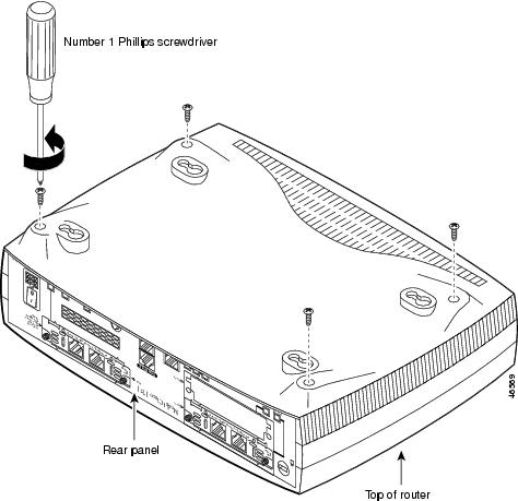
Opening the chassis requires a number 1 Phillips screwdriver.
Step 1
Step 2
Step 3
Figure 1 Removing the Chassis Screws
Step 4
Step 5
Step 6
Step 7
Opening the Chassis of a Rack-Mount Router
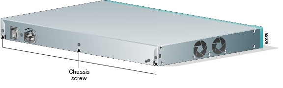
Follow the steps below to open the chassis of a Cisco 1760 router. Opening the chassis requires a flat-head screwdriver.
Step 1
Step 2
Figure 2 Removing the Cisco 1760 Chassis Screws
Step 3
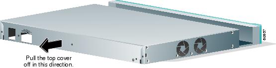
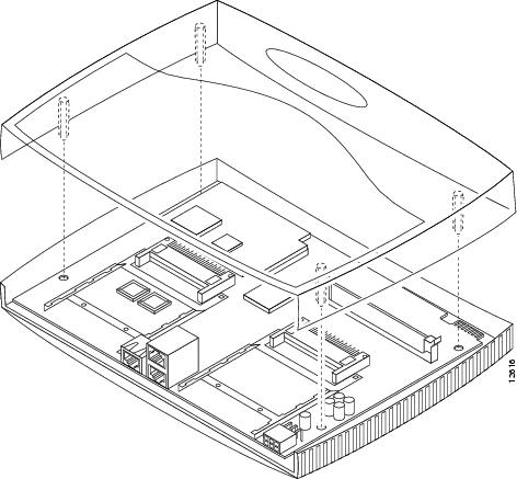
Figure 3 Removing the Top Cover of the Router
Step 4
Locating Modules
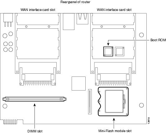
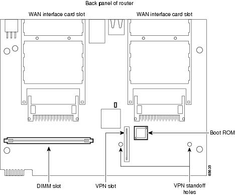
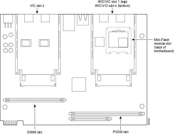
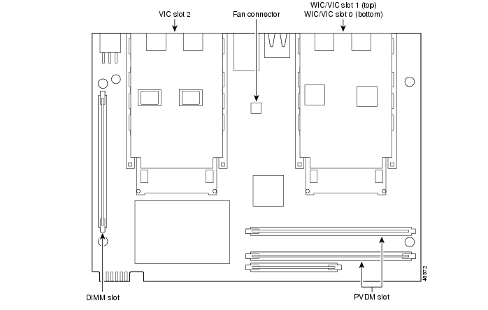
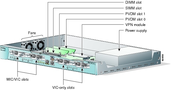
Figure 4 and Figure 6 show where to install DIMMs and mini-flash modules on the Cisco 1720 and Cisco 1750 router motherboards. Figure 5 shows where to install DIMMs on the Cisco 1721 router motherboard. Figure 7 shows where to install DIMMs on the Cisco 1751 router motherboard. Figure 8 shows where to install DIMMs and mini-flash SIMMs on the Cisco 1760 router motherboard.
Note
Figure 4 Cisco 1720 Motherboard—Memory Locations
Figure 5 Cisco 1721 Motherboard—Memory Locations
Figure 6 Cisco 1750 Motherboard—Memory Locations
Figure 7 Cisco 1751 Motherboard—Memory Locations
Figure 8 Cisco 1760 Motherboard—Memory Locations
Installing a Mini-Flash Module
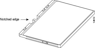
You can install a mini-flash module (shown in Figure 9 below) in a Cisco 1720 or Cisco 1750 router to increase the amount of router flash memory. (This section does not apply to Cisco 1721, Cisco 1751 or Cisco 1760 routers.)
Figure 9 Mini-Flash Module
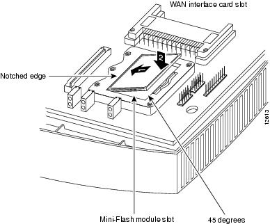
Take the following steps to install a mini-flash module on the motherboard:
Step 1
Step 2
Step 3
Step 4
Figure 10 Installing a Mini-Flash Module
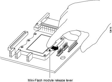
Removing a Mini-Flash Module
Take the following steps to remove a mini-flash module:
Step 1
Step 2
Figure 11 Removing a Mini-Flash Module
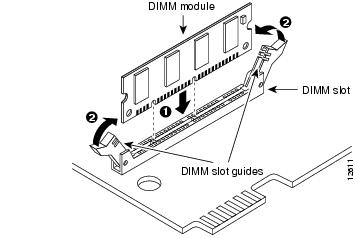
Installing a Dual In-Line Memory Module
You can install a dual in-line memory module (DIMM) to increase the amount of dynamic RAM (DRAM) in the Cisco 1720, Cisco 1721, Cisco 1750, Cisco 1751, or Cisco 1760 routers.
Warning
Take the following steps to install a DIMM on the router motherboard:
Step 1
Step 2
Step 3
Step 4
Step 5
Figure 12 Installing a DIMM
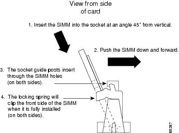
Installing a SIMM
You can install one SIMM to increase the amount of flash memory in the router. Follow these steps to install a SIMM on the router motherboard.
Warning
Take the following steps to install a SIMM on the router motherboard:
Step 1
Step 2
Step 3
Caution
Step 4
Figure 13 Installing a SIMM
Closing the Chassis of a Desktop Router
After installing memory on the motherboard, follow these steps to close the chassis:
Step 1
Note
Step 2
Step 3
Caution
Step 4
Figure 14 Closing the Chassis
Closing the Chassis of a Rack-Mount Router
After installing memory or data modules on the motherboard, close the chassis by following these steps:
Step 1
Step 2
Obtaining Documentation
Cisco documentation and additional literature are available on Cisco.com. Cisco also provides several ways to obtain technical assistance and other technical resources. These sections explain how to obtain technical information from Cisco Systems.
Cisco.com
You can access the most current Cisco documentation at this URL:
http://www.cisco.com/univercd/home/home.htm
You can access the Cisco website at this URL:
You can access international Cisco websites at this URL:
http://www.cisco.com/public/countries_languages.shtml
Documentation DVD
Cisco documentation and additional literature are available in a Documentation DVD package, which may have shipped with your product. The Documentation DVD is updated regularly and may be more current than printed documentation. The Documentation DVD package is available as a single unit.
Registered Cisco.com users (Cisco direct customers) can order a Cisco Documentation DVD (product number DOC-DOCDVD=) from the Ordering tool or Cisco Marketplace.
Cisco Ordering tool:
http://www.cisco.com/en/US/partner/ordering/
Cisco Marketplace:
http://www.cisco.com/go/marketplace/
Ordering Documentation
You can find instructions for ordering documentation at this URL:
http://www.cisco.com/univercd/cc/td/doc/es_inpck/pdi.htm
You can order Cisco documentation in these ways:
•
http://www.cisco.com/en/US/partner/ordering/
•
Documentation Feedback
You can send comments about technical documentation to bug-doc@cisco.com.
You can submit comments by using the response card (if present) behind the front cover of your document or by writing to the following address:
Cisco Systems
Attn: Customer Document Ordering
170 West Tasman Drive
San Jose, CA 95134-9883We appreciate your comments.
Cisco Product Security Overview
Cisco provides a free online Security Vulnerability Policy portal at this URL:
http://www.cisco.com/en/US/products/products_security_vulnerability_policy.html
From this site, you can perform these tasks:
•
•
•
A current list of security advisories and notices for Cisco products is available at this URL:
If you prefer to see advisories and notices as they are updated in real time, you can access a Product Security Incident Response Team Really Simple Syndication (PSIRT RSS) feed from this URL:
http://www.cisco.com/en/US/products/products_psirt_rss_feed.html
Reporting Security Problems in Cisco Products
Cisco is committed to delivering secure products. We test our products internally before we release them, and we strive to correct all vulnerabilities quickly. If you think that you might have identified a vulnerability in a Cisco product, contact PSIRT:
•
•
Tip
Never use a revoked or an expired encryption key. The correct public key to use in your correspondence with PSIRT is the one that has the most recent creation date in this public key server list:
http://pgp.mit.edu:11371/pks/lookup?search=psirt%40cisco.com&op=index&exact=on
In an emergency, you can also reach PSIRT by telephone:
•
•
Obtaining Technical Assistance
For all customers, partners, resellers, and distributors who hold valid Cisco service contracts, Cisco Technical Support provides 24-hour-a-day, award-winning technical assistance. The Cisco Technical Support Website on Cisco.com features extensive online support resources. In addition, Cisco Technical Assistance Center (TAC) engineers provide telephone support. If you do not hold a valid Cisco service contract, contact your reseller.
Cisco Technical Support Website
The Cisco Technical Support Website provides online documents and tools for troubleshooting and resolving technical issues with Cisco products and technologies. The website is available 24 hours a day, 365 days a year, at this URL:
http://www.cisco.com/techsupport
Access to all tools on the Cisco Technical Support Website requires a Cisco.com user ID and password. If you have a valid service contract but do not have a user ID or password, you can register at this URL:
http://tools.cisco.com/RPF/register/register.do
Note
Submitting a Service Request
Using the online TAC Service Request Tool is the fastest way to open S3 and S4 service requests. (S3 and S4 service requests are those in which your network is minimally impaired or for which you require product information.) After you describe your situation, the TAC Service Request Tool provides recommended solutions. If your issue is not resolved using the recommended resources, your service request is assigned to a Cisco TAC engineer. The TAC Service Request Tool is located at this URL:
http://www.cisco.com/techsupport/servicerequest
For S1 or S2 service requests or if you do not have Internet access, contact the Cisco TAC by telephone. (S1 or S2 service requests are those in which your production network is down or severely degraded.) Cisco TAC engineers are assigned immediately to S1 and S2 service requests to help keep your business operations running smoothly.
To open a service request by telephone, use one of the following numbers:
Asia-Pacific: +61 2 8446 7411 (Australia: 1 800 805 227)
EMEA: +32 2 704 55 55
USA: 1 800 553-2447For a complete list of Cisco TAC contacts, go to this URL:
http://www.cisco.com/techsupport/contacts
Definitions of Service Request Severity
To ensure that all service requests are reported in a standard format, Cisco has established severity definitions.
Severity 1 (S1)—Your network is "down," or there is a critical impact to your business operations. You and Cisco will commit all necessary resources around the clock to resolve the situation.
Severity 2 (S2)—Operation of an existing network is severely degraded, or significant aspects of your business operation are negatively affected by inadequate performance of Cisco products. You and Cisco will commit full-time resources during normal business hours to resolve the situation.
Severity 3 (S3)—Operational performance of your network is impaired, but most business operations remain functional. You and Cisco will commit resources during normal business hours to restore service to satisfactory levels.
Severity 4 (S4)—You require information or assistance with Cisco product capabilities, installation, or configuration. There is little or no effect on your business operations.
Obtaining Additional Publications and Information
Information about Cisco products, technologies, and network solutions is available from various online and printed sources.
•
http://www.cisco.com/go/marketplace/
•
•
•
http://www.cisco.com/go/iqmagazine
•
•
http://www.cisco.com/en/US/learning/index.html
Use this document in conjunction with your router installation and configuration guide, the Regulatory Compliance and Safety Information document for your router, and the Cisco IOS configuration guides and command references.
CCSP, CCVP, the Cisco Square Bridge logo, Follow Me Browsing, and StackWise are trademarks of Cisco Systems, Inc.; Changing the Way We Work, Live, Play, and Learn, and iQuick Study are service marks of Cisco Systems, Inc.; and Access Registrar, Aironet, ASIST, BPX, Catalyst, CCDA, CCDP, CCIE, CCIP, CCNA, CCNP, Cisco, the Cisco Certified Internetwork Expert logo, Cisco IOS, Cisco Press, Cisco Systems, Cisco Systems Capital, the Cisco Systems logo, Cisco Unity, Empowering the Internet Generation, Enterprise/Solver, EtherChannel, EtherFast, EtherSwitch, Fast Step, FormShare, GigaDrive, GigaStack, HomeLink, Internet Quotient, IOS, IP/TV, iQ Expertise, the iQ logo, iQ Net Readiness Scorecard, LightStream, Linksys, MeetingPlace, MGX, the Networkers logo, Networking Academy, Network Registrar, Packet, PIX, Post-Routing, Pre-Routing, ProConnect, RateMUX, ScriptShare, SlideCast, SMARTnet, StrataView Plus, TeleRouter, The Fastest Way to Increase Your Internet Quotient, and TransPath are registered trademarks of Cisco Systems, Inc. and/or its affiliates in the United States and certain other countries.
All other trademarks mentioned in this document or Website are the property of their respective owners. The use of the word partner does not imply a partnership relationship between Cisco and any other company. (0502R)
Installing and Upgrading Memory in Cisco 1700 Series Routers
Copyright © 2005 Cisco Systems, Inc. All rights reserved.