Feedback Feedback
|
Table Of Contents
Cisco 12006 and Cisco 12406 Router Chassis Replacement Instructions
Preventing Electrostatic Discharge Damage
Grounding the Replacement Chassis
Removing and Installing the Chassis
Preparing the Defective Chassis
Disconnecting Power from the Power Distribution Units
Disconnecting Line Card Interface Cables
Disconnecting Alarm Card Cables
Transferring System Components
Transferring the Power Modules
Transferring RP and Line Cards
Transferring the Clock and Scheduler Cards, Switch Fabric Cards, and Alarm Cards
Transferring the Power Distribution Unit
Removing the Defective Chassis
Detaching the Supplemental Bonding and Grounding Connection
Removing the Defective Chassis from a Tabletop or Flat Surface Site
Removing the Defective Chassis from the Equipment Rack
Installing the Replacement Chassis
Installing the Chassis on a Tabletop or Flat Surface
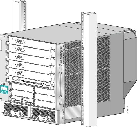
Installing the Chassis in the Equipment Rack
Reattaching the Supplemental Bonding and Grounding Connection
Reconnecting Alarm Cards Cables
Reconnecting Line Card Network Interface Cables
Reconnecting Power to the Router
Checking Conditions Before System Startup
Powering On the Router and Verifying Operation
Packaging the Replaced Chassis for Shipment
Regulatory, Compliance, and Safety Information
Translated Safety Warnings and Agency Approvals
Electromagnetic Compatibility Regulatory Statements
Class A Notice for Taiwan and Other Traditional Chinese Markets
Obtaining Technical Assistance
Obtaining Additional Publications and Information
Cisco 12006 and Cisco 12406 Router Chassis Replacement Instructions
Product Number: GSR6/120=
Document Order Number: DOC-7816109=This publication explains how to remove and install the Cisco 12006 or Cisco 12406 Router chassis. It includes referrals to other Cisco publications that include the information required to complete these procedures.
These two router models are differentiated by the switching capacity of the switch fabric installed in the router:
•
Cisco 12006 Router—2.5-Gbps switch fabric
•
Other than the switch fabric, these routers are identical in most respects. Any differences between the models are described in the appropriate locations. Unless otherwise noted, all information in this publication applies to both router models.
Contents
•
•
•
•
•
Replacement Chassis Overview
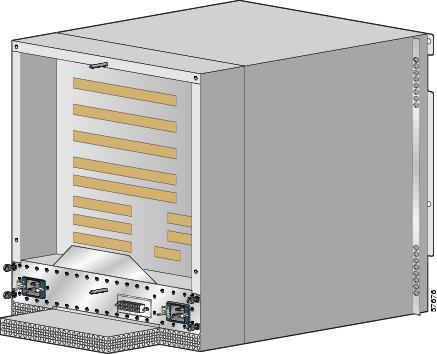
The replacement chassis for the Cisco 12006 and Cisco 12406 Routers is the sheet-metal enclosure of the router, without components such as the power supplies, line cards, route processors (RPs), switch fabric card set, alarm cards, power distribution unit, and blower module. (See Figure 1.) The same chassis is used for both DC-powered and AC-powered Cisco 12006 or Cisco 12406 Routers.
Figure 1 Replacement Chassis (Front View)
The chassis is an integrated, sheet-metal assembly that includes the following items:
•
•
•
•
•
•
•
The chassis can be rack mounted or placed on a stable flat surface.
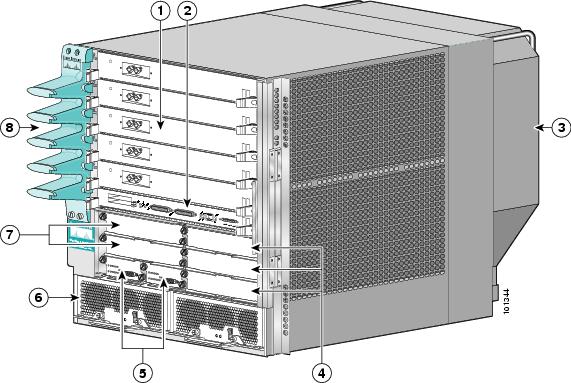
Figure 2 shows a front view of the chassis, with the locations of the system parts that must be transferred from the defective chassis to the replacement chassis.
Figure 3 shows a read view of the chassis, with the locations of the system parts that must be transferred from the defective chassis to the replacement chassis.
Figure 2 Cisco 12006 or Cisco 12406 Router (Front View)
Line cards
Alarm cards
RP
Power modules
Blower module
CSCs
SFCs
Cable-management bracket
Figure 3 Cisco 12006 or Cisco 12406 Router (Rear View)
Blower module
Air exhaust vents
Blower module LEDs
PDU (behind Blower module; AC PDU shown)
Blower module handle
-
Preparing for Installation
Information related to installation preparations is presented in the following sections:
•
Related Documentation
The following Cisco publications contain additional information:
•
•
Tools and Equipment
You need the following items to replace a Cisco 12006 or Cisco 12406 Router chassis:
•
•
•
•
•
•
•
•
Safety Guidelines
Before you perform any procedure in this publication, review the safety guidelines in this section to avoid injuring yourself or damaging the equipment. In addition, review the safety warnings listed in the Regulatory Compliance and Safety Information for the Cisco 12000 Series Router publication (Document Number 78-4347-xx) that accompanied your router before installing, configuring, or maintaining the router.
The following guidelines are for your safety and to protect equipment. The guidelines do not include all hazards. Be alert.
Safety with Equipment
•
•
•
•
•
•
Safety with Electricity
•
•
•
•
•
•
•
–
–
–
In addition, observe the following guidelines when working with any equipment that is disconnected from a power source but still connected to telephone or network wiring:
•
•
•
•
Preventing Electrostatic Discharge Damage
Many router components can be damaged by static electricity. Some components can be damaged by voltages as low as 30V, while static voltages as high as 35,000V can be generated just by handling plastic or foam packing material, or by sliding assemblies across plastic and carpets. Not exercising the proper electrostatic discharge (ESD) precautions can result in intermittent or complete component failures. To minimize the potential for ESD damage, observe the following guidelines:
•
Caution
•
•
•
•
•
Figure 4 Connecting an ESD-preventive Wrist Strap to the Chassis
Before You Begin
You will need to remove all the components except the air filter from the defective chassis and reinstall them in the replacement chassis. The recommended procedures are as follows:
•
•
•
•
•
This approach has the advantage of protecting the system components, such as line cards and switch fabric cards, against damage by eliminating the need to store them even temporarily outside their card cages. It also helps ensure that the physical configuration of the router is maintained, because each transferred component is installed in the same location in the replacement chassis that it occupied in the defective chassis.
Before you begin, you should study the router chassis being replaced. Note where all the external cables are attached and how they are routed to the chassis. If necessary, label the cables so that they can be reinstalled correctly on the system after the chassis is replaced.
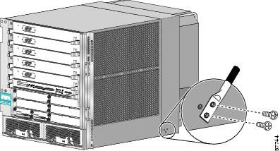
Grounding the Replacement Chassis
When the replacement chassis is near the rack site, temporarily connect the central office grounding system or interior equipment grounding system to the network equipment building systems (NEBS) supplemental bonding and grounding receptacle on the router. There are three threaded inserts on the right side of the chassis near the rear panel. (See Figure 5.)
Figure 5 NEBS Bonding and Grounding Receptacle
For more information on the bonding and grounding cable and connector requirements, refer to Chapter 2 of the Cisco 12006 and Cisco 12406 Router Installation and Configuration Guide.
Removing and Installing the Chassis
Procedures for removing and installing the chassis are described in the following sections:
•
•
•
•
Preparing the Defective Chassis
To prepare the defective chassis for component removal you must disconnect the power from the PDU and disconnect the RP cables, line card cables, interface cables, and alarm card cables. These procedures are described below.
Disconnecting Power from the Power Distribution Units
Before transferring the components from the defective chassis to the replacement chassis, you must first power down the router. Although many of the components in this procedure support OIR, that is, they are hot-swappable, the router must be powered down before you remove the PDU.
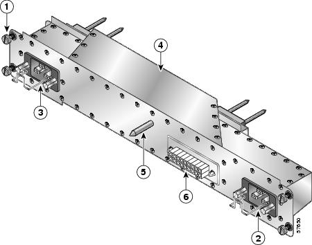
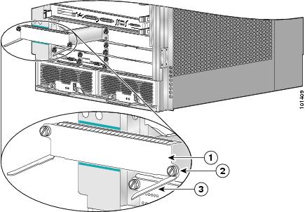
The power distribution unit (PDU) is the point where facility power is connected to the router. The PDU is located at the rear of the chassis, behind the blower module. Figure 6 shows the rear view of a router with the AC PDU installed.
For routers equipped with an AC-powered subsystem, the PDU is an AC PDU, and facility AC power connects to the PDU through two AC power cord receptacles. (See Figure 7.)
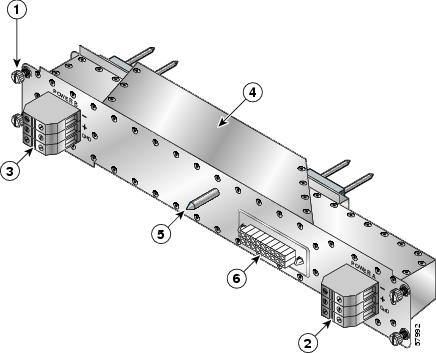
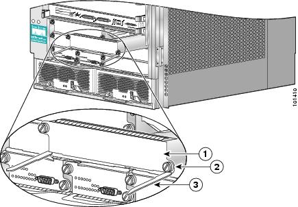
For routers equipped with a DC-powered subsystem, the PDU is a DC PDU, and facility DC power connects to the PDU through source DC power cable leads clamped into two DC connector blocks. (See Figure 8 and Figure 9.)
Figure 6 AC-Powered Router—Rear View, Blower Module Removed
Figure 7 AC Power Distribution Unit
Captive screw (four)
AC power distribution unit
AC power cord receptacle A
Guide pin
AC power cord receptacle B
Blower module connector
Figure 8 DC Power Distribution Unit
Captive screw (four)
DC power distribution unit
DC power connector block A
Guide pin
DC power connector block B
Blower module connector
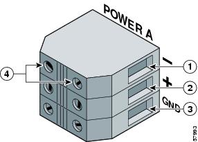
Each of the DC power connector blocks on the DC PDU has three terminal ports. (See Figure 9.) Leads from the facility DC source power should be connected to the terminal block: the negative lead is connected to the top port, the positive lead is connected to the middle port, and the ground lead is connected to the bottom port.
Figure 9 PDU DC Power Connector Block
Negative Terminal Port
Ground Terminal Port
Positive Terminal Port
Terminal Port Connector Screws
Warning
To remove power from the router, follow these steps:
Step 1
Step 2
Step 3
•
•
Step 4
•
•
•
•
•
•
Caution
Disconnecting RP Cables
You must disconnect any cables that are connected to the RP console port, auxiliary port, or either of the Ethernet ports, RJ-45 or MII (GRP only). Identify and write down each of the RP cable connections on a piece of paper before you disconnect the cables. After disconnecting the cables, move them away from the chassis and place them safely aside. You will reconnect the cables to the RP in the replacement chassis in a later procedure.
Disconnecting Line Card Interface Cables
To disconnect line card interface cables, follow these steps:
Step 1
Step 2
•
•
Step 3
Step 4
After you disconnect the cables and the line card cable-management bracket from each card, carefully pull the cables bundles out of the way until the cables can be reinstalled on the replacement chassis and reconnected to the line card.
Disconnecting Alarm Card Cables
You must disconnect any cable that is connected to the external alarm port on either or both of the alarm cards. Identify the alarm cable connections and write them down on a piece of paper before you disconnect the cables. After disconnecting the cables, remove them from the chassis and place them safely aside. You will reconnect the cables to the alarm cards in the replacement chassis in a later procedure.
Transferring System Components
The instructions for transferring system components between the old and the new chassis are described in the following sections:
•
•
•
•
Transferring the Power Modules
Cisco 12006 and Cisco 12406 Routers can be equipped with either AC-input power supplies or DC-input PEMs. In either case, they are removed and installed using the same procedure.
To remove a power module, follow these steps:
Step 1
Step 2
Step 3
Step 4
a.
b.
Step 5
Step 6
Step 7
Figure 10 Removing a Power Module (AC-Input Power Supply Shown)
To install a power module, use Figure 11 as a reference and follow these steps:
Step 1
Step 2
Step 3
Step 4
Note
Step 5
Step 6
Figure 11 Installing a Power Module (AC-Input Power Supply Shown)
Transferring RP and Line Cards
You must remove the line cards and RP(s) from the RP and line card cage, then install them in the card cage in the replacement chassis. To maintain proper air flow and for EMI performance, card slot blanks must be installed in slots without cards. RP and line card captive screws must be tightened on the replacement chassis to ensure electromagnetic compliance (EMC).
Caution
Cisco 12000 Series line cards are OIR (hot-swappable) FRUs. RPs also support OIR, but are hot-swappable only when the system is equipped with two RPs.
To remove an RP or line card from the RP and line card cage, see Figure 13 and follow these steps:
Step 1
Step 2
•
•
Step 3
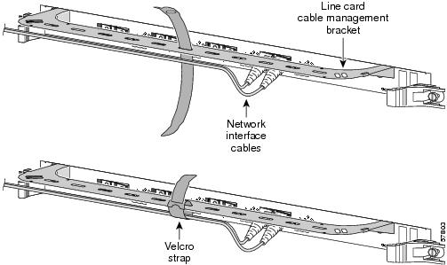
Figure 12 Line Card Cable-Management Brackets with Velcro Straps
Step 4
Step 5
a.
b.
Figure 13 Removing an RP or Line Card from the Card Cage
Caution
c.
Caution
Caution
Step 6
•
•
a.
Caution
b.
c.
Caution
d.
e.
f.
Note
Note
Transferring the Clock and Scheduler Cards, Switch Fabric Cards, and Alarm Cards
Cisco 12006 and Cisco 12406 Routers are equipped with chassis slots for two CSCs, three SFCs, and two alarm cards. (See Figure 2.)
You must remove the two CSCs (or single CSC and CSC filler blank), three SFCs, and two alarm cards from their slots in the defective chassis and install them in the replacement chassis. The captive screws of each card must be tightened on the replacement chassis to ensure electromagnetic compliance (EMC).
Transferring the Clock and Scheduler Cards
Cisco 12006 and Cisco 12406 Routers configured for redundant CSCs will have two CSCs installed in the two CSC slots; a router configured for nonredundant operation will have one CSC installed in one of the CSC slots, and will have a CSC blank filler installed in the second CSC slot. Figure 14 shows a partially ejected CSC.
To transfer the CSCs from the defective chassis to the replacement chassis, remove each CSC or CSC blank filler and immediately install the CSC or CSC blank filler in the same slot of the replacement chassis as described in the procedure in this section.
Figure 14 Removing and Installing a Clock and Scheduler Card
To transfer a CSC, see Figure 14 and follow these steps:
Step 1
Step 2
a.
b.
c.
d.
Step 3
a.
b.
c.
d.
Caution
e.
Transferring the Switch Fabric Cards
The three SFCs occupy the three half-width slots on the lower right side of the chassis. (See Figure 2.) Figure 15 shows a partially-ejected SFC.
To transfer the SFCs from the defective chassis to the replacement chassis, remove each SFC and immediately install the SFC in the same slot of the replacement chassis as described in the procedure in this section.
Figure 15 Removing and Installing a Switch Fabric Card
To transfer a switch fabric card, see Figure 15 and follow these steps:
Step 1
Step 2
a.
b.
c.
d.
Step 3
a.
b.
c.
d.
Caution
e.
Transferring Alarm Cards
The two alarm cards occupy the card slots in the alarm card bay. These slots are located on the bottom left side of the chassis, directly underneath the clock and scheduler card slots. (See Figure 2.) Figure 16 shows a partially-ejected alarm card.
To transfer the alarm cards from the defective chassis to the replacement chassis, remove each alarm card and immediately install the alarm card in the same slot of the replacement chassis as described in the procedure in this section.
Figure 16 Removing and Installing an Alarm Card
To transfer an alarm card, see Figure 16 and follow these steps:
Step 1
Step 2
a.
b.
c.
Step 3
a.
b.
Note
c.
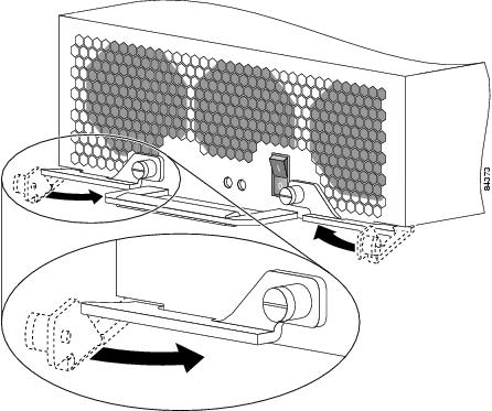
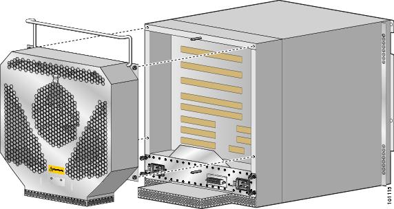
Removing the Blower Module
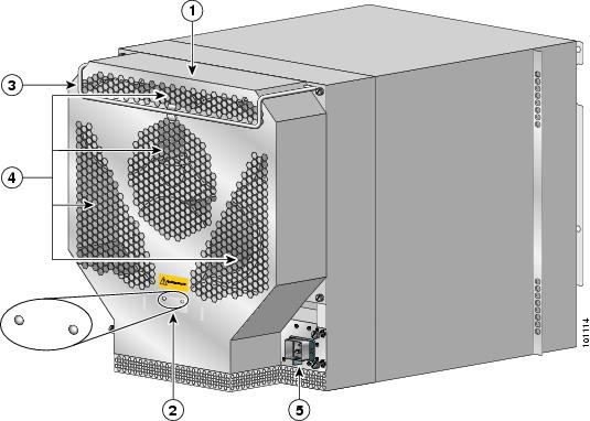
Cisco 12006 and Cisco 12406 Routers are equipped with one blower module, which mounts on the rear of the chassis. (See Figure 17.)
Note
Figure 17 Blower Module (Handle in the Up Position)
To remove the blower module, follow these steps:
Step 1
Note
Step 2
Step 3
Caution
Step 4
Step 5
Transferring the Power Distribution Unit
Cisco 12006 and Cisco 12406 Routers are equipped with one PDU, which mounts on the rear of the chassis, near the bottom, behind the blower module. (See Figure 6.) With the exception of the power wiring connectors, the DC PDU and the AC PDU are similar physical packages for purposes removing and installing the PDU. The procedure in this section applies equally to both the AC and DC PDU.
Note
Warning
To transfer the PDU from the defective chassis to the replacement chassis, follow these steps:
Step 1
Step 2
a.
Note
b.
c.
Step 3
a.
b.
c.
d.
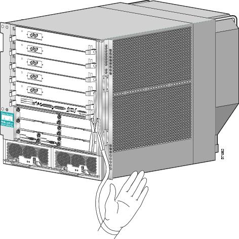
Except for the blower module, which you will install on the replacement chassis after you have reconnected facility power to the PDU in a later procedure, the router—consisting of the replacement chassis and its system components—is ready to be set in place of the existing, defective chassis.
Removing the Defective Chassis
This section contains the following procedures:
•
•
•
Detaching the Supplemental Bonding and Grounding Connection
If the central office ground system or interior equipment grounding system is connected to the supplemental bonding and grounding receptacle on the router chassis, detach the supplemental bonding and grounding cable from the defective chassis. (See Figure 5.)
Removing the Defective Chassis from a Tabletop or Flat Surface Site
To remove the defective chassis from a tabletop or flat surface installation site, follow these steps:
Step 1
Caution
Step 2
If you plan to return the defective chassis to the factory, place the chassis on the shipping base that was used to ship the replacement chassis and repackage it in the shipping container that enclosed the replacement chassis.
Removing the Defective Chassis from the Equipment Rack
This section contains the following procedures:
•
•
Removing the Chassis When The Chassis is Mounted Directly on the Rack Rails
To remove the defective chassis from an equipment rack, follow these steps:
Step 1
Step 2
Step 3
Caution
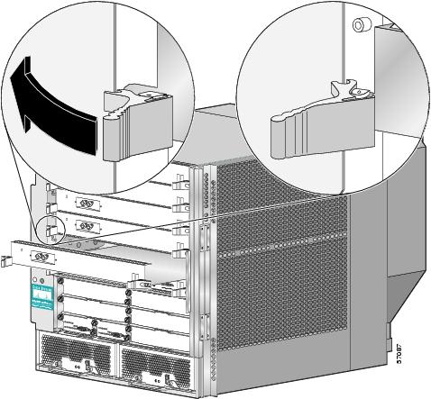
Removing the Chassis When the Chassis is Mounted Using the Center-Mount Brackets
If the chassis is installed using the center-mount brackets, see Figure 18 and follow these steps to remove the chassis from the equipment rack:
Step 1
Step 2
This step helps you align the replacement chassis with the narrow upper center-mount brackets when you insert the replacement chassis into the rack.
Step 3
Step 4
Caution
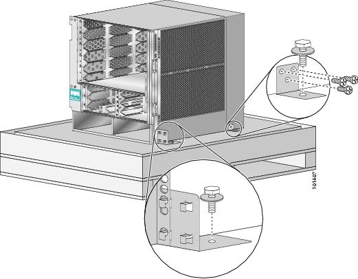
Figure 18 Center-Mount Brackets
Installing the Replacement Chassis
This section explains the following procedures:
•
•
•
•
•
•
Installing the Chassis on a Tabletop or Flat Surface
To install the router on a tabletop or stable flat surface, follow these steps:
Step 1
Step 2
Step 3
Installing the Chassis in the Equipment Rack
If the original router chassis was removed from an equipment rack, install the replacement chassis back in the rack using the same mounting screw positions and mounting method used for the original router chassis.
To install the chassis in a rack, follow these steps:
Step 1
Step 2
Note
Step 3
a.
b.
c.
d.
Caution
When the chassis is installed in a rack using the center-mount bracket kit, put two screws in each of the lower brackets and one screw in each of the upper stand-off brackets.
Step 4
Step 5
Reattaching the Supplemental Bonding and Grounding Connection
If the central office ground system or interior equipment grounding system is to be connected to the supplemental bonding and grounding receptacle on the Cisco 12006 and Cisco 12406 Router chassis, connect the supplemental bonding and grounding cable to the chassis. (See Figure 5.)
Reconnecting RP Cables
You must reconnect any cables that were disconnected from the RP console port, auxiliary port, or either of the Ethernet ports, RJ-45 or MII.
Reconnecting Alarm Cards Cables
If you disconnected a cable from the external alarm port on either or both of the alarm cards, you must reconnect those cables now.
Note
Reconnecting Line Card Network Interface Cables
To reconnect network interface cables to a line card, see Figure 12 and follow these steps:
Step 1
Step 2
Step 3
Step 4
Step 5
Step 6
Step 7
Note
Reconnecting Power to the Router
This section contains the following procedures:
•
•
Reconnecting Power to a Router Equipped with the AC Power Distribution Unit
To reconnect source AC to the AC PDU, see Figure 7 and follow these steps:
Step 1
Step 2
Step 3
Step 4
Reconnecting Power to a Router Equipped with the DC Power Distribution Unit
To reconnect source DC power to the DC PDU, see Figure 8 and Figure 9 and follow these steps:
Step 1
Step 2
Caution
Warning
Step 3
a.
b.
c.
Step 4
Installing the Blower Module
After the chassis power has been reconnected to the PDU, install the blower module on the replacement chassis.
To install the blower module, see Figure 17 and follow these steps:
Step 1
Caution
Step 2
Caution
Step 3
Note
Step 4
Step 5
Restarting the Router
This section contains the following procedures:
•
•
Checking Conditions Before System Startup
Before attempting to startup the router after replacing the chassis, confirm the following conditions:
•
•
•
•
•
•
•
•
•
Note
•
Powering On the Router and Verifying Operation
To power on the router and verify that it restarts successfully, follow these steps:
Step 1
Step 2
During the startup, the system displays the system banner information. Check the startup banner and displays to ensure that the system has restarted properly and that all the interfaces reinitialize properly.
Step 3
•
–
–
•
–
–
–
Step 4
Step 5
Note
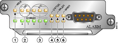
Figure 19 Alarm Card LEDs On/Off Conditions
MBus status LED
Critical alarm LED
CSC status LEDs (two)
Major alarm LED
SFC status LEDs (three)
Minor alarm LED
Step 6
LEDs that normally should be off:
•
•
•
•
LEDs that normally should be on:
•
•
•
Step 7
If the power modules do not power up, or if the system or any interfaces do not initialize properly, see Chapter 4, "Troubleshooting the Installation" in the Cisco 12006 and Cisco 12406 Router Installation and Configuration Guide. If you are still unable to resolve the problem, contact your Cisco service representative for assistance.
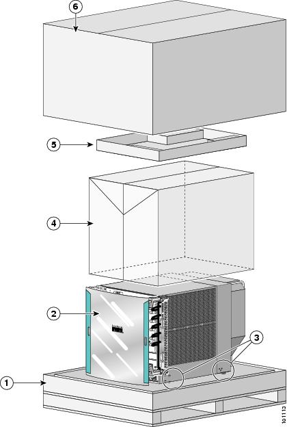
Packaging the Replaced Chassis for Shipment
To repackage the chassis to return it to the factory, follow these steps:
Step 1
Note
Step 2
Step 3
Step 4
Step 5
Step 6
The chassis is now repackaged and ready to be transported. Use a forklift or pallet jack to move the repackaged chassis.
Figure 20 Router Packaging Components
Pallet base
Plastic bag
Router
Accessory kit tray
Hold-down brackets with bolts
Outer shipping container
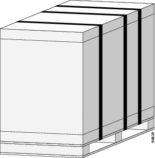
Figure 21 Cisco 12006 or Cisco 12406 Router Secured to Pallet Base
Regulatory, Compliance, and Safety Information
This section includes regulatory, compliance, and safety information in the following sections:
•
•
Translated Safety Warnings and Agency Approvals
The complete list of translated safety warnings and agency approvals is available in the Regulatory Compliance and Safety Information for Cisco 12000 Series Routers publication (Document Number 78-4347-xx).
Electromagnetic Compatibility Regulatory Statements
FCC Class A Compliance
This equipment has been tested and found to comply with the limits for a Class A digital device, pursuant to part 15 of the FCC rules. These limits are designed to provide reasonable protection against harmful interference when the equipment is operated in a commercial environment. This equipment generates, uses, and can radiate radio-frequency energy and, if not installed and used in accordance with the instruction manual, may cause harmful interference to radio communications. Operation of this equipment in a residential area is likely to cause harmful interference, in which case users will be required to correct the interference at their own expense.
Modifying the equipment without Cisco's authorization may result in the equipment no longer complying with FCC requirements for Class A digital devices. In that event, your right to use the equipment may be limited by FCC regulation and you may be required to correct any interference to radio or television communication at your own expense.
You can determine whether your equipment is causing interference by turning it off. If the interference stops, it was probably caused by the Cisco equipment or one of its peripheral devices. If the equipment causes interference to radio or television reception, try to correct the interference by using one or more of the following measures:
•
•
•
•
CISPR 22
This apparatus complies with CISPR 22/EN55022 Class B radiated and conducted emissions requirements.
Canada
English Statement of Compliance
This class A digital apparatus complies with Canadian ICES-003.
French Statement of Compliance
Cet appareil numérique de la classe A est conforme à la norme NMB-003 du Canada.
Europe (EU)
This apparatus complies with EN55022 Class B and EN55024 standards when used as ITE/TTE equipment, and EN300386 for Telecommunications Network Equipment (TNE) in both installation environments, telecommunication centers and other indoor locations.
VCCI Class A Notice for Japan
Class A Notice for Hungary
Class A Notice for Taiwan and Other Traditional Chinese Markets
Class A Notice for Korea
Obtaining Documentation
Cisco provides several ways to obtain documentation, technical assistance, and other technical resources. These sections explain how to obtain technical information from Cisco Systems.
Cisco.com
You can access the most current Cisco documentation on the World Wide Web at this URL:
http://www.cisco.com/univercd/home/home.htm
You can access the Cisco website at this URL:
International Cisco websites can be accessed from this URL:
http://www.cisco.com/public/countries_languages.shtml
Documentation CD-ROM
Cisco documentation and additional literature are available in a Cisco Documentation CD-ROM package, which may have shipped with your product. The Documentation CD-ROM is updated regularly and may be more current than printed documentation. The CD-ROM package is available as a single unit or through an annual or quarterly subscription.
Registered Cisco.com users can order a single Documentation CD-ROM (product number DOC-CONDOCCD=) through the Cisco Ordering tool:
http://www.cisco.com/en/US/partner/ordering/ordering_place_order_ordering_tool_launch.html
All users can order annual or quarterly subscriptions through the online Subscription Store:
http://www.cisco.com/go/subscription
Ordering Documentation
You can find instructions for ordering documentation at this URL:
http://www.cisco.com/univercd/cc/td/doc/es_inpck/pdi.htm
You can order Cisco documentation in these ways:
•
http://www.cisco.com/en/US/partner/ordering/index.shtml
•
Documentation Feedback
You can submit comments electronically on Cisco.com. On the Cisco Documentation home page, click Feedback at the top of the page.
You can send your comments in e-mail to bug-doc@cisco.com.
You can submit comments by using the response card (if present) behind the front cover of your document or by writing to the following address:
Cisco Systems
Attn: Customer Document Ordering
170 West Tasman Drive
San Jose, CA 95134-9883We appreciate your comments.
Obtaining Technical Assistance
For all customers, partners, resellers, and distributors who hold valid Cisco service contracts, the Cisco Technical Assistance Center (TAC) provides 24-hour, award-winning technical support services, online and over the phone. Cisco.com features the Cisco TAC website as an online starting point for technical assistance.
Cisco TAC Website
The Cisco TAC website (http://www.cisco.com/tac) provides online documents and tools for troubleshooting and resolving technical issues with Cisco products and technologies. The Cisco TAC website is available 24 hours a day, 365 days a year.
Accessing all the tools on the Cisco TAC website requires a Cisco.com user ID and password. If you have a valid service contract but do not have a login ID or password, register at this URL:
http://tools.cisco.com/RPF/register/register.do
Opening a TAC Case
The online TAC Case Open Tool (http://www.cisco.com/tac/caseopen) is the fastest way to open P3 and P4 cases. (Your network is minimally impaired or you require product information). After you describe your situation, the TAC Case Open Tool automatically recommends resources for an immediate solution. If your issue is not resolved using these recommendations, your case will be assigned to a Cisco TAC engineer.
For P1 or P2 cases (your production network is down or severely degraded) or if you do not have Internet access, contact Cisco TAC by telephone. Cisco TAC engineers are assigned immediately to P1 and P2 cases to help keep your business operations running smoothly.
To open a case by telephone, use one of the following numbers:
Asia-Pacific: +61 2 8446 7411 (Australia: 1 800 805 227)
EMEA: +32 2 704 55 55
USA: 1 800 553-2447For a complete listing of Cisco TAC contacts, go to this URL:
http://www.cisco.com/warp/public/687/Directory/DirTAC.shtml
TAC Case Priority Definitions
To ensure that all cases are reported in a standard format, Cisco has established case priority definitions.
Priority 1 (P1)—Your network is "down" or there is a critical impact to your business operations. You and Cisco will commit all necessary resources around the clock to resolve the situation.
Priority 2 (P2)—Operation of an existing network is severely degraded, or significant aspects of your business operation are negatively affected by inadequate performance of Cisco products. You and Cisco will commit full-time resources during normal business hours to resolve the situation.
Priority 3 (P3)—Operational performance of your network is impaired, but most business operations remain functional. You and Cisco will commit resources during normal business hours to restore service to satisfactory levels.
Priority 4 (P4)—You require information or assistance with Cisco product capabilities, installation, or configuration. There is little or no effect on your business operations.
Obtaining Additional Publications and Information
Information about Cisco products, technologies, and network solutions is available from various online and printed sources.
•
http://www.cisco.com/en/US/products/products_catalog_links_launch.html
•
•
http://www.cisco.com/go/packet
•
http://www.cisco.com/go/iqmagazine
•
http://www.cisco.com/en/US/about/ac123/ac147/about_cisco_the_internet_protocol_journal.html
•
http://www.cisco.com/en/US/learning/le31/learning_recommended_training_list.html
This document is to be used in conjunction with the Cisco 12006 and Cisco 12406 Router Installation and Configuration Guide.
Copyright © 2004 Cisco Systems, Inc. All rights reserved.