Feedback Feedback
|
Table Of Contents
Cisco 12006 and Cisco 12406 Router Power System Procedures Guide
Power Supply and PDU Compatibility
Preventing Electrostatic Discharge Damage
Removing and Replacing an AC PEM
Troubleshooting the AC Power Supply Installation
Removing and Replacing an AC PDU
Removing and Replacing a DC PEM
Troubleshooting the DC Power Supply Installation
Removing and Replacing a DC PDU
Regulatory, Compliance, and Safety Information
Translated Safety Warnings and Agency Approvals
Electromagnetic Compatibility Regulatory Statements
Class A Notice for Taiwan and Other Traditional Chinese Markets
Cisco Product Security Overview
Reporting Security Problems in Cisco Products
Obtaining Technical Assistance
Cisco Technical Support and Documentation Website
Definitions of Service Request Severity
Obtaining Additional Publications and Information
Cisco 12006 and Cisco 12406 Router Power System Procedures Guide
Product Numbers: 12000/6-AC-PEM=, 12000/6-DC-PEM=, 12000/6-AC-PDU=, 12000/6-DC-PDU=, GSR6-AC-PDU=, PWR-GSR6-AC=, PWR-GSR6-DC=, GSR6-DC-PDU=
Upgrade Kits: 12000/6-AC-UP=, 12000/6-DC-UP=This publication contains removal and replacement procedures for the AC and DC power systems used with Cisco 12006 and Cisco 12406 routers.
Note
The illustrations in this guide represent both original and upgraded power supplies and PDUs shipping with the Cisco 12006 and Cisco 12406 routers. Depending on your system, these components may not look exactly like those in your chassis, but the removal and replacement procedures are essentially the same. Illustrations represent original and new models where appropriate. For clarity, most chassis covers are not shown in the illustrations.
Contents
The following sections are included in this publication:
•
•
•
•
•
•
•
•
•
•
•
Power Supply and PDU Compatibility
Cisco 12006 and Cisco 12406 routers are available with either an AC or DC power supply system. The two types of power supplies for these systems are:
•
•
Removal and replacement procedures are the same for either type of power supply, but because of their power capacity and physical differences, you cannot mix different types of power supplies in the chassis.
Caution
Before you attempt to install or replace them (Table 1), be sure you know your system power supplies and associated PDU.
Installing Upgrade Kits
When installing a power system upgrade kit, replace the following components.
•
–
–
•
–
–
Note
Prerequisites and Preparation
Before you perform any of the procedures in this guide, be sure that you:
•
•
•
–
–
For additional information about obtaining documentation see the "Obtaining Documentation" section.
Safety Guidelines
Before you perform any procedure in this publication, review the safety guidelines in this section to avoid injuring yourself or damaging the equipment.
Safety Warnings
Safety warnings appear throughout this publication in procedures that, if performed incorrectly, may harm you. A warning symbol precedes each warning statement. The following warning is an example of a safety warning. It identifies the warning symbol and associates it with a bodily injury hazard.
Warning
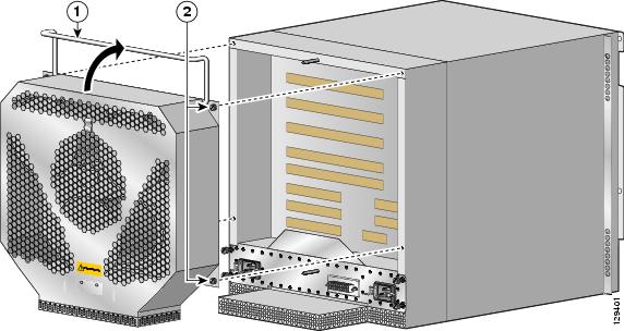
Preventing Electrostatic Discharge Damage
Many router components can be damaged by static electricity. Not exercising the proper electrostatic discharge (ESD) precautions can result in intermittent or complete component failures. To minimize the potential for ESD damage, always use an ESD-preventive antistatic wrist strap (or ankle strap) and ensure that it makes good skin contact.
Note
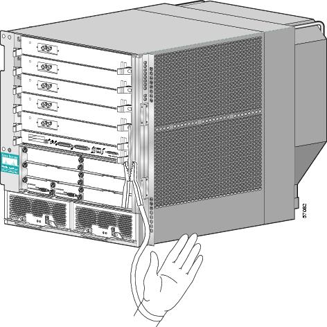
Before performing the procedures in this guide, attach an ESD-preventive strap to your wrist and connect the leash to the chassis or to another grounded, bare metal surface as shown in Figure 1.
Figure 1 Connecting an ESD-preventive Wrist Strap to the Chassis
Installation Guidelines
Cisco 12006 and Cisco 12406 routers support online insertion and removal (OIR) for power supplies. If you are replacing a redundant power supply, you can remove and install a power supply while the system remains powered on without causing an electrical hazard or damage to the system. This feature enables you to replace a power supply while the system maintains all routing information and ensures session preservation.
However, to maintain operational redundancy, maintain proper cooling, and meet EMI compliance standards, you must have two working power supplies installed. When you remove a failed power supply with the router in operation, perform the replacement as quickly as possible. Before you begin the removal and installation procedure, make sure you have the tools and the replacement power supply ready.
Caution
Caution
Required Tools and Equipment
The following tools and equipment are required to remove and install power equipment:
•
•
•
Related Documentation
The following publications contain additional information:
•
•
For additional information about related documentation, see the "Obtaining Documentation" section.
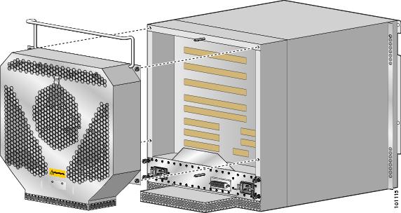
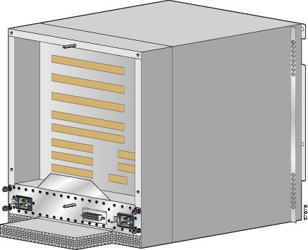
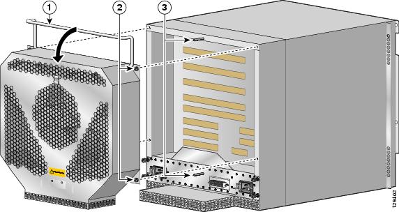
Removing and Replacing an AC PEM
This section contains the procedure to remove and replace an AC PEM from the chassis. Before you begin this procedure, be sure to read the "Installation Guidelines" section.
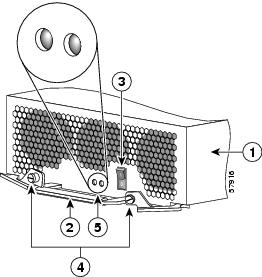
Figure 2 identifies the components of an AC power supply.
Figure 2 AC Power Supply Components
AC PEM
Captive screws/release levers
Handle
AC input/DC output status indicators
Power On/Off switch
Use the following procedure to remove and replace an AC power supply.
Caution
Step 1
Step 2
Step 3
Step 4
a.
b.
c.
Warning
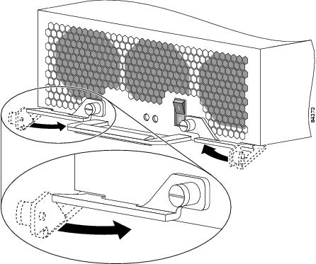
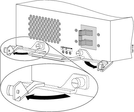
Figure 3 Releasing the AC Power Supply
Step 5
a.
Caution
b.
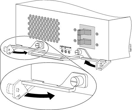
Figure 4 Seating the AC Power Supply
Step 6
Step 7
Step 8
The AC Input and DC Output power indicators on the front of the power supply should light. If the indicators do not light, see the "Troubleshooting the AC Power Supply Installation" section.
Troubleshooting the AC Power Supply Installation
Use the following procedure to troubleshoot the AC power supply if it is not operating properly after installation.
Step 1
•
–
–
Step 2
•
•
–
•
Step 3
•
–
–
•
If the indicator is off, toggle the power switch off and then on. If the indicator remains off after several attempts to power it on, replace the power supply with a spare.
Removing and Replacing an AC PDU
Use the following procedure to remove and replace an AC PDU. Before you begin this procedure, read the "Installation Guidelines" section.
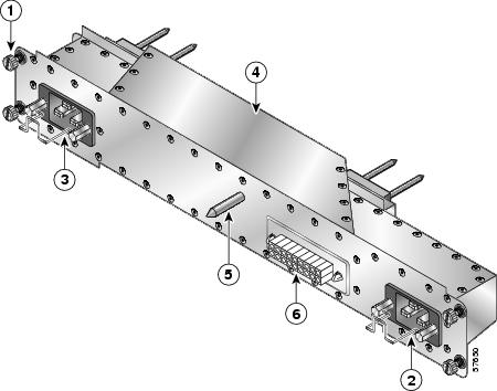
Figure 5 identifies the components of the AC PDU.
Figure 5 AC Power Distribution Unit
Captive screw
AC power distribution unit
AC power cord connector/retention clip (A)
Guide pin
AC power cord connector/retention clip (B)
Blower module connector
Caution
Step 1
Step 2
Step 3
Step 4
•
•
Figure 6 Unseating the AC Power Supply
Step 5
Step 6
a.
b.
c.
Figure 7 Removing the Blower Module
Step 7
a.
b.
c.
Note
Figure 8 Removing the AC PDU
Step 8
Step 9
a.
b.
Caution
c.
d.
Figure 9 Installing the Blower Module
Step 10
Step 11
Step 12
Step 13
a.
Caution
b.
c.
Figure 10 Seating the AC Power Supply
Step 14
The AC Input Power and DC Output Power indicators on the power supplies should light. If the indicators do not light, see the "Troubleshooting the AC Power Supply Installation" section.
Removing and Replacing a DC PEM
This section contains the procedure to remove and replace a DC power supply from the chassis. Before you begin this procedure, read the "Installation Guidelines" section.
Figure 11 identifies the components of a DC power supply.
Figure 11 DC Power Entry Module Components
DC PEM
Captive screws/release levers
Handle
Cooling fan
Power on/off switch
DCI/DCO/RVP status indicators
Use the following procedure to remove and replace a DC power supply.
Caution
Step 1
Step 2
Warning
Step 3
a.
b.
c.
Warning
Figure 12 Releasing the DC Power Supply
Step 4
a.
Caution
b.
Figure 13 Seating the DC Power Supply
Step 5
Step 6
The DCI (DC Input) and DCO (DC Output) power indicators on the front of the power supply should light. If the indicators do not light, or the RVP (Reversed Polarity) indicator is on, see the "Troubleshooting the DC Power Supply Installation" section.
Troubleshooting the DC Power Supply Installation
Use the following procedure to troubleshoot the DC power supply if it is not operating properly after installation.
Step 1
•
–
–
Step 2
•
•
•
Step 3
•
–
–
•
If the indicator is off, toggle the power switch off and then on. If the indicator remains off after several attempts to power it on, replace the power supply with a spare.
•
Correct wiring to the DC power connector block (see Figure 20).
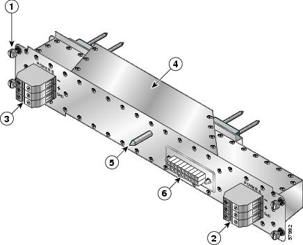
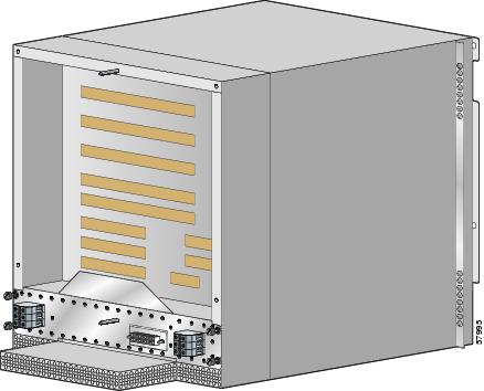
Removing and Replacing a DC PDU
Use the following procedure to remove and replace a DC PDU. before beginning this procedure, read the "Installation Guidelines" section.
Figure 14 identifies the components of the DC PDU.
Figure 14 DC Power Distribution Unit
Captive screw
DC power distribution unit
DC power connector block (A)
Guide pin
DC power connector block (B)
Blower module connector
Caution
Step 1
Step 2
Warning
Step 3
•
•
Figure 15 Unseating the DC Power Supply
Step 4
a.
b.
c.
Figure 16 Removing the Blower Module
Step 5
a.
b.
c.
d.
Warning
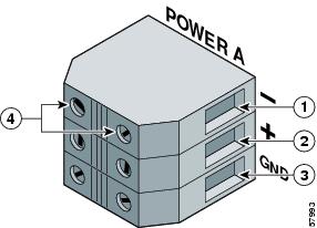
Figure 17 Disconnecting the DC Power Leads
Negative terminal port
Ground terminal port
Positive terminal port
Terminal port connector screws
Step 6
a.
b.
c.
Note
Figure 18 Removing the DC PDU
Step 7
Step 8
a.
b.
Caution
c.
d.
Figure 19 Installing the Blower Module
Step 9
a.
b.
c.
d.
Warning
Figure 20 Disconnecting the DC Power Leads
Negative terminal port
Ground terminal port
Positive terminal port
Terminal port connector screws
Step 10
Step 11
a.
Caution
b.
c.
Figure 21 Seating a DC Power Supply
Step 12
The output power OK and input power OK indicators on the power supplies should light. If the indicators do not light, see the "Troubleshooting the DC Power Supply Installation" section.
Regulatory, Compliance, and Safety Information
This section includes regulatory, compliance, and safety information in the following sections:
•
•
Translated Safety Warnings and Agency Approvals
The complete list of translated safety warnings and agency approvals is available in the Regulatory Compliance and Safety Information for Cisco 12000 Series Routers publication (Document Number 78-4347-xx).
Electromagnetic Compatibility Regulatory Statements
FCC Class A Compliance
This equipment has been tested and found to comply with the limits for a Class A digital device, pursuant to part 15 of the FCC rules. These limits are designed to provide reasonable protection against harmful interference when the equipment is operated in a commercial environment. This equipment generates, uses, and can radiate radio-frequency energy and, if not installed and used in accordance with the instruction manual, may cause harmful interference to radio communications. Operation of this equipment in a residential area is likely to cause harmful interference, in which case users will be required to correct the interference at their own expense.
Modifying the equipment without Cisco authorization may result in the equipment no longer complying with FCC requirements for Class A digital devices. In that event, your right to use the equipment may be limited by FCC regulation and you may be required to correct any interference to radio or television communication at your own expense.
You can determine whether your equipment is causing interference by turning it off. If the interference stops, it was probably caused by the Cisco equipment or one of its peripheral devices. If the equipment causes interference to radio or television reception, try to correct the interference by using one or more of the following measures:
•
•
•
•
CISPR 22
This apparatus complies with CISPR 22/EN55022 Class B radiated and conducted emissions requirements.
Canada
English Statement of Compliance
This class A digital apparatus complies with Canadian ICES-003.
French Statement of Compliance
Cet appareil numérique de la classe A est conforme à la norme NMB-003 du Canada.
Europe—EU
This apparatus complies with EN55022 Class B and EN55024 standards when used as ITE/TTE equipment, and EN300386 for Telecommunications Network Equipment (TNE) in both installation environments, telecommunication centers and other indoor locations.
VCCI Class A Notice for Japan
Class A Notice for Hungary
Class A Notice for Taiwan and Other Traditional Chinese Markets
Class A Notice for Korea
Obtaining Documentation
Cisco documentation and additional literature are available on Cisco.com. Cisco also provides several ways to obtain technical assistance and other technical resources. These sections explain how to obtain technical information from Cisco Systems.
Cisco.com
You can access the most current Cisco documentation at this URL:
http://www.cisco.com/techsupport
You can access the Cisco website at this URL:
You can access international Cisco websites at this URL:
http://www.cisco.com/public/countries_languages.shtml
Product Documentation DVD
Cisco documentation and additional literature are available in the Product Documentation DVD package, which may have shipped with your product. The Product Documentation DVD is updated regularly and may be more current than printed documentation.
The Product Documentation DVD is a comprehensive library of technical product documentation on portable media. The DVD enables you to access multiple versions of hardware and software installation, configuration, and command guides for Cisco products and to view technical documentation in HTML. With the DVD, you have access to the same documentation that is found on the Cisco website without being connected to the Internet. Certain products also have .pdf versions of the documentation available.
The Product Documentation DVD is available as a single unit or as a subscription. Registered Cisco.com users (Cisco direct customers) can order a Product Documentation DVD (product number DOC-DOCDVD=) from the Ordering tool or Cisco Marketplace.
Cisco Ordering tool:
http://www.cisco.com/en/US/partner/ordering/
Cisco Marketplace:
http://www.cisco.com/go/marketplace/
Ordering Documentation
Beginning June 30, 2005, registered Cisco.com users may order Cisco documentation at the Product Documentation Store in the Cisco Marketplace at this URL:
http://www.cisco.com/go/marketplace/
Cisco supports documentation orders using the Ordering tool:
•
http://www.cisco.com/en/US/partner/ordering/
•
http://www.cisco.com/univercd/cc/td/doc/es_inpck/pdi.htm
•
Documentation Feedback
You can rate and provide feedback about Cisco technical documents by completing the online feedback form that appears with the technical documents on Cisco.com.
You can send comments about Cisco documentation to bug-doc@cisco.com.
You can submit comments by using the response card (if present) behind the front cover of your document or by writing to the following address:
Cisco Systems
Attn: Customer Document Ordering
170 West Tasman Drive
San Jose, CA 95134-9883We appreciate your comments.
Cisco Product Security Overview
Cisco provides a free online Security Vulnerability Policy portal at this URL:
http://www.cisco.com/en/US/products/products_security_vulnerability_policy.html
From this site, you can perform these tasks:
•
•
•
A current list of security advisories and notices for Cisco products is available at this URL:
If you prefer to see advisories and notices as they are updated in real time, you can access a Product Security Incident Response Team Really Simple Syndication (PSIRT RSS) feed from this URL:
http://www.cisco.com/en/US/products/products_psirt_rss_feed.html
Reporting Security Problems in Cisco Products
Cisco is committed to delivering secure products. We test our products internally before we release them, and we strive to correct all vulnerabilities quickly. If you think that you might have identified a vulnerability in a Cisco product, contact PSIRT:
•
An emergency is either a condition in which a system is under active attack or a condition for which a severe and urgent security vulnerability should be reported. All other conditions are considered nonemergencies.
•
In an emergency, you can also reach PSIRT by telephone:
•
•
Tip
Never use a revoked or an expired encryption key. The correct public key to use in your correspondence with PSIRT is the one linked in the Contact Summary section of the Security Vulnerability Policy page at this URL:
http://www.cisco.com/en/US/products/products_security_vulnerability_policy.htm
The link on this page has the current PGP key ID in use.
Obtaining Technical Assistance
Cisco Technical Support provides 24-hour-a-day award-winning technical assistance. The Cisco Technical Support & Documentation website on Cisco.com features extensive online support resources. In addition, if you have a valid Cisco service contract, Cisco Technical Assistance Center (TAC) engineers provide telephone support. If you do not have a valid Cisco service contract, contact your reseller.
Cisco Technical Support and Documentation Website
The Cisco Technical Support and Documentation website provides online documents and tools for troubleshooting and resolving technical issues with Cisco products and technologies. The website is available 24 hours a day, at this URL:
http://www.cisco.com/techsupport
Access to all tools on the Cisco Technical Support & Documentation website requires a Cisco.com user ID and password. If you have a valid service contract but do not have a user ID or password, you can register at this URL:
http://tools.cisco.com/RPF/register/register.do
Note
Submitting a Service Request
Using the online TAC Service Request Tool is the fastest way to open S3 and S4 service requests. (S3 and S4 service requests are those in which your network is minimally impaired or for which you require product information.) After you describe your situation, the TAC Service Request Tool provides recommended solutions. If your issue is not resolved using the recommended resources, your service request is assigned to a Cisco engineer. The TAC Service Request Tool is located at this URL:
http://www.cisco.com/techsupport/servicerequest
For S1 or S2 service requests or if you do not have Internet access, contact the Cisco TAC by telephone. (S1 or S2 service requests are those in which your production network is down or severely degraded.) Cisco engineers are assigned immediately to S1 and S2 service requests to help keep your business operations running smoothly.
To open a service request by telephone, use one of the following numbers:
Asia-Pacific: +61 2 8446 7411 (Australia: 1 800 805 227)
EMEA: +32 2 704 55 55
USA: 1 800 553-2447For a complete list of Cisco TAC contacts, go to this URL:
http://www.cisco.com/techsupport/contacts
Definitions of Service Request Severity
To ensure that all service requests are reported in a standard format, Cisco has established severity definitions.
Severity 1 (S1)—Your network is "down," or there is a critical impact to your business operations. You and Cisco will commit all necessary resources around the clock to resolve the situation.
Severity 2 (S2)—Operation of an existing network is severely degraded, or significant aspects of your business operation are negatively affected by inadequate performance of Cisco products. You and Cisco will commit full-time resources during normal business hours to resolve the situation.
Severity 3 (S3)—Operational performance of your network is impaired, but most business operations remain functional. You and Cisco will commit resources during normal business hours to restore service to satisfactory levels.
Severity 4 (S4)—You require information or assistance with Cisco product capabilities, installation, or configuration. There is little or no effect on your business operations.
Obtaining Additional Publications and Information
Information about Cisco products, technologies, and network solutions is available from various online and printed sources.
•
http://www.cisco.com/go/marketplace/
•
•
•
http://www.cisco.com/go/iqmagazine
or view the digital edition at this URL:
http://ciscoiq.texterity.com/ciscoiq/sample/
•
•
http://www.cisco.com/en/US/products/index.html
•
http://www.cisco.com/discuss/networking
•
http://www.cisco.com/en/US/learning/index.html
This document is to be used in conjunction with the Cisco 12000/6Router Installation and Configuration Guide.