Feedback Feedback
|
Table Of Contents
8-Port Unchannelized E3/T3 Line Card Overview
Software and Hardware Compatibility
Line Card, Router, and Processor Compatibility
8-Port Unchannelized E3/T3 Line Card Overview
This chapter describes the Cisco 10000 series 8-port unchannelized E3/T3 line card (referred to as the 8-port unchannelized E3/T3 line card), and contains the following sections:
•
Software and Hardware Compatibility
•
•
Line Card Summary
Table 15-1 8-Port Unchannelized E3/T3 Line Card Summary
ESR-8E3/DS3=
8-port unchannelized E3/T3 line card
Initial Cisco IOS releases for PRE-1:
12.0(22)S and later releases of Cisco IOS 12.0S
Initial Cisco IOS releases for PRE-2:
12.0(22)S and later releases of Cisco IOS 12.0S
12.0(20)ST and later releases of
12.0ST
12.3(7)XI and later releases of Cisco IOS 12.3XIFor registered Cisco.com users, use Software Advisor to determine the software releases for this line card.
In unchannelized (also called clear channel) operation, each E3/T3 interface port provides a single high-speed data channel. Each port can be configured to use any portion of the E3/T3 available bandwidths. The maximum E3 bandwidth is 34.386 Mbps; the maximum T3 bandwidth is 44.736 Mbps.
The line card provides Cisco 10000 series routers with eight E3 or T3 high-density unchannelized interface ports. The line card:
•
•
•
•
If you are a registered Cisco.com user, see Feature Navigator for supported features.
Software and Hardware Compatibility
To check the minimum software requirements of Cisco IOS software with the hardware installed on your router, Cisco maintains the Software Advisor tool on Cisco.com. This tool does not verify whether line cards within a system are compatible, but does provide the minimum Cisco IOS requirements for individual hardware line cards, modules, or options.
Note
To access Software Advisor, click Login at Cisco.com, type Software Advisor in the SEARCH box, and click Go. Click the link for the Software Advisor tool.
Choose a product family or enter a specific product number to search for the minimum supported software release needed for your hardware.
Line Card, Router, and Processor Compatibility
Table 15-2 lists router model, line card, and processor compatibility.
Table 15-2 Line Card, Router, and Processor Compatibility
8-port unchannelized E3/T3 line card
Yes
Yes
Yes
Yes
No
Note
Note
LEDs
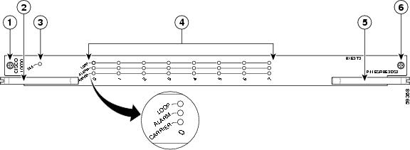
The 8-port unchannelized E3/T3 line card LEDs are shown in Figure 15-1.
Figure 15-1 8-Port Unchannelized E3/T3 Line Card Faceplate Description
Captive screws
Ports 0 to 7 status LEDs
Top ejector lever
Bottom ejector lever
FAIL LED
Bottom captive screw
Table 15-3 provides a description of the 8-port unchannelized E3/T3 line card LEDs.
Physical Specifications
The 8-port unchannelized E3/T3 line card physical specifications are shown in Table 15-4.
Slot Locations
The line card slot designations are shown in this section. See Figure 15-2 for line card slot designations for the Cisco 10008 router and Figure 15-3 for line card slot designations for the Cisco 10005 router.
Figure 15-2 Line Card Slot Designations—Cisco 10008 Router
Blower module
PRE slot 0A
Primary PEM
PRE slot 0B
Redundant PEM
Line card slots 5 to 8
Line card slots 1 to 4
The 8-port unchannelized E3/T3 line card can be installed in slot 1 through slot 8.
Figure 15-3 Line Card Slot Designations—Cisco 10005 Router
The 8-port unchannelized E3/T3 line card can be installed in slot 1 through slot 5.
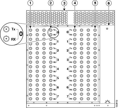
Cables and Connectors
External network connections to the 8-port unchannelized E3/T3 line card are made through the BNC connectors mounted on the rear of the Cisco 10000 chassis, using 75-ohm coaxial cable (Figure 15-4). The approved cables for use with the 8-port unchannelized E3/T3 line card are cables conforming to WECO standards 728A, 734A, or 734D. Use cable lengths up to 450 ft (137.16 m). 735A cables can be used with lengths up to 225 ft (68.58 m).
Figure 15-4 Cisco 10008 Chassis (Rear)—BNC Connectors
Line card slot 8
Line card slot 4
Line cards slot 5
Line card slot 1
Blower module
Power supply
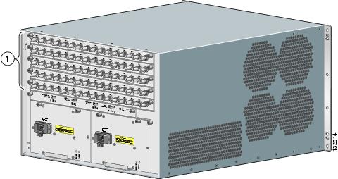
The BNC connectors on the rear of the chassis, which use coaxial cable, are used with the 8-port unchannelized E3/T3 line card (Figure 15-5).
Figure 15-5 Cisco 10005 Chassis (Rear)—BNC Connectors
Also see Appendix A, "Cisco 10005 Extender Card Information" for information about the extender card which must be used with the 8-port unchannelized E3/T3 line card in the Cisco 10005 chassis.
All Cisco 10005 cards connect to a backplane in the center of the chassis, and require extender cards to deliver the alarm, BITS clock, and DS3 signals to the rear of the chassis to make them accessible. The Cisco 10005 alarm extender card and T3/E3 extender card extend and terminate these signals.
Go to Chapter 16, "Preparing for Installation" to begin the installation or replacement of the line card.
For troubleshooting information, see Chapter 18, "Troubleshooting the Installation."