Cisco ONS 15600 Troubleshooting Guide, Release 6.0
Chapter 1, General Troubleshooting

Table Of Contents

General Troubleshooting

1.1  Network Troubleshooting Tests

1.1.1  Facility Loopbacks

1.1.2  Payload Loopbacks

1.1.3  Terminal Loopbacks

1.1.4  Cross-Connect (XC) Loopbacks

1.2  Troubleshooting Optical Circuit Paths With Loopbacks

1.2.1  Perform a Facility (Line) Loopback or Payload Loopback on a Source-Node Optical Port

Create the Facility (Line) Loopback or Payload Loopback on the Source Optical Port

Test and Clear the Facility (Line) Loopback or Payload Loopback Circuit

Test the Optical Card

1.2.2  Perform a Terminal (Inward) Loopback on a Source-Node Optical Port

Create the Terminal (Inward) Loopback on a Source-Node Optical Port

Test and Clear the Terminal Loopback Circuit

Test the ASAP Card

1.2.3  Perform an XC Loopback on the Source Optical Port

Create the XC Loopback on the Source-Node Optical Port

Test and Clear the XC Loopback Circuit

Test the Alternate SSXC Card

Retest the Preferred SSXC Card

1.2.4  Perform a Facility (Line) Loopback or Payload Loopback on an Intermediate-Node Optical Port

Create a Facility (Line) Loopback or Payload Loopback on an Intermediate-Node Optical Port

Test and Clear the Facility (Line) Loopback or Payload Loopback Circuit

Test the Optical Card

1.2.5  Perform a Facility (Line) Loopback or Payload Loopback on a Destination-Node Optical Port

Create the Facility (Line) Loopback or Payload Loopback on a Destination-Node Optical Port

Test and Clear the Optical Facility (Line) Loopback or Payload Loopback Circuit

Test the Optical Card

1.2.6  Perform a Terminal Loopback on a Destination-Node Optical Port

Create the Terminal Loopback on a Destination-Node Optical Port

Test and Clear the Optical Terminal Loopback Circuit

Test the ASAP Card

1.3  Troubleshooting an Ethernet Circuit Path With Loopbacks

1.3.1  Perform a Facility (Line) Loopback on a Source-Node Ethernet Port

Create the Facility (Line) Loopback on the Source-Node Ethernet Port

Test and Clear the Facility (Line) Loopback Circuit

Test the ASAP Card

1.3.2  Perform a Terminal (Inward) Loopback on a Source-Node Ethernet Port

Create the Terminal (Inward) Loopback on a Source-Node Ethernet Port

Test and Clear the Ethernet Terminal Loopback Circuit

Test the ASAP Card

1.3.3  Create a Facility (Line) Loopback on an Intermediate-Node Ethernet Port

Create a Facility (Line) Loopback on an Intermediate-Node Ethernet Port

Test and Clear the Ethernet Facility (Line) Loopback Circuit

Test the ASAP Card

1.3.4  Create a Terminal (Inward) Loopback on an Intermediate-Node Ethernet Port

Create a Terminal Loopback on an Intermediate-Node Ethernet Port

Test and Clear the Ethernet Terminal Loopback Circuit

Test the ASAP Card

1.3.5  Perform a Facility (Line) Loopback on a Destination-Node Ethernet Port

Create the Facility (Line) Loopback on a Destination-Node Ethernet Port

Test and Clear the Ethernet Facility (Line) Loopback Circuit

Test the ASAP Card

1.3.6  Perform a Terminal Loopback on a Destination-Node Ethernet Port

Create the Terminal Loopback on a Destination-Node Ethernet Port

Test and Clear the Ethernet Terminal Loopback Circuit

Test the ASAP Card

1.4  Using CTC Diagnostics

1.4.1  Card LED Lamp Tests

1.4.2  Retrieve Diagnostics File Button

Off-Load the Diagnostics File

1.5  Restoring the Database to a Previous or Original Configuration

1.5.1  Node is Functioning Improperly or Has Incorrect Data

1.6  PC Connectivity Troubleshooting

1.6.1  PC System Minimum Requirements

1.6.2  Sun System Minimum Requirements

1.6.3  Supported Platforms, Browsers, and JREs

1.6.4  Unsupported Platforms and Browsers

1.6.5  Retrieve the Node Information

1.6.6  Unable to Ping Your PC

1.6.7  Browser Login Does Not Launch Java

1.6.8  Unable to Verify the NIC Connection on your PC

1.6.9  TCP/IP Connection is Lost

Ping the ONS 15600

1.7  CTC Operation Troubleshooting

1.7.1  Cisco Transport Controller Installation Wizard Hangs

Abort the Stalled Installation Wizard

1.7.2  Browser Stalls When Downloading JAR Files From TSC Card

1.7.3  Cisco Transport Controller Does Not Launch

1.7.4  Sluggish Cisco Transport Controller Operation or Login Problems

1.7.5  Node Icon is Gray on Cisco Transport Controller Network View

1.7.6  Cisco Transport Controller Does Not Recognize the Node

1.7.7  Username or Password Mismatch

1.7.8  Superuser Password Needs to Be Reset

Reset the ONS 15600 Password

1.7.9  No IP Connectivity Exists Between Nodes

1.7.10  DCC Connection Lost

1.7.11  Loss of IP Communication Between Nodes on an OSPF LAN

1.8  Circuits and Timing

1.8.1  ONS 15600 Switches Timing Reference

1.8.2  Holdover Synchronization Alarm

1.8.3  Free-Running Synchronization Mode

1.8.4  Daisy-Chained BITS Not Functioning

1.8.5  Circuits Remain in PARTIAL Status

1.9  Fiber and Cabling

1.9.1  Bit Errors Appear for an Optical Traffic Card

1.9.2  Faulty Fiber-Optic Connections

1.9.3  Optical Traffic Card Transmit and Receive Levels

1.10  Power Supply Problems


General Troubleshooting


This chapter provides procedures for troubleshooting the most common problems encountered when operating a Cisco ONS 15600. To troubleshoot specific ONS 15600 alarms, see Chapter 2, "Alarm Troubleshooting." If you cannot find what you are looking for, contact the Cisco Technical Assistance Center (1 800 553-2447).

This chapter begins with the following sections on network problems:

Network Troubleshooting Tests—Describes loopbacks and hairpin circuits, which you can use to test circuit paths through the network or logically isolate faults.


Note For network acceptance tests, refer to the Cisco ONS 15600 Procedure Guide.


Troubleshooting Optical Circuit Paths With Loopbacks—Explains how to perform the tests described in the "Network Troubleshooting Tests" section for OC-N ports and cards.

Troubleshooting an Ethernet Circuit Path With Loopbacks—Explains how to perform the tests described in the "Network Troubleshooting Tests" section for Gigabit Ethernet (GIGE) ASAP card ports.

The remaining sections describe symptoms, problems, and solutions that are categorized according to the following topics:

Using CTC Diagnostics—Provides procedures for testing LED operation and downloading a machine-readable diagnostic information file to be used by Technical Support.

Restoring the Database to a Previous or Original Configuration—Provides troubleshooting for node operation errors that might require procedures to restore software data or restoring the node to the default setup.

PC Connectivity Troubleshooting—Provides troubleshooting procedures for PC and network connectivity to the ONS 15600.

CTC Operation Troubleshooting—Provides troubleshooting procedures for CTC log-in or operation problems.

Circuits and Timing—Provides troubleshooting procedures for circuit creation, error reporting, and timing reference errors and alarms.

Fiber and Cabling—Provides troubleshooting procedures for fiber and cabling connectivity errors.

Power Supply Problems—Provides troubleshooting information for common power supply issues.

1.1  Network Troubleshooting Tests

Use loopbacks to test newly created circuits before running live traffic or to logically locate the source of a network failure. All ONS 15600 optical (OC-N) cards allow loopbacks.


Caution On optical cards, a loopback can only be applied to a port that is out of service.

1.1.1  Facility Loopbacks

The following sections give general information about facility loopback operations and specific information about ONS 15600 card loopback activity.

1.1.1.1  General Behavior

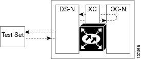
A facility loopback tests the line interface unit (LIU) of an ASAP card or OC-48 card and related cabling. After applying a facility loopback on a port, use a test set to run traffic over the loopback. A successful facility loopback isolates the LIU or the cabling plant as the potential cause of a network problem. To test an OC-N port or Ethernet port, connect an optical test set to the port and perform a facility loopback. Alternately, use a loopback or hairpin circuit on a card that is farther along the circuit path.

Figure 1-1 shows a facility/payload loopback on an OC-N port.

Figure 1-1 Facility/Payload Loopback Process on an OC-N Port


Caution Before performing a facility loopback on an OC-N port, be sure the ASAP card contains at least two data communications channel (DCC) paths to the node where the card is installed. A second DCC provides a nonlooped path to log into the node after the loopback is applied, enabling you to remove the facility loopback. Ensuring a second DCC is not necessary if you are directly connected to the ONS 15600 containing the loopbacked ASAP card.

1.1.1.2  Card Behavior

Loopbacks either terminate or bridge the loopback signal. When a port terminates a facility loopback signal, the signal only loops back to the originating port and is not transmitted downstream. When a port bridges a loopback signal, the signal loops back to the originating port and is also transmitted downstream.

The loopback itself is listed in the Conditions window. For example, the window would list the LPBKFACILITY condition for a tested port. (The Alarms window will show AS-MT, which means that alarms are suppressed on the facility during loopback.)

In addition to the Conditions window listing, the following behaviors occur:

If an electrical or optical port is in the Out-of-Service and Management, Disabled (OOS-MA,DSBLD) service state, it injects an AIS signal upstream and downstream.

When an electrical or optical port is placed in the OOS-MA,MT service state before loopback testing, the port clears the AIS signal upstream and downstream unless there is a service-affecting defect that would also cause an AIS signal to be injected. For more information about placing ports into alternate states for testing, refer to the "Change Card Settings" chapter of the Cisco ONS 15600 Procedure Guide.


Caution A lock out of protection must be executed before putting a two-fiber or four-fiber BLSR span into a facility loopback state. That is, a span lockout of one side (such as the east side) of a two-fiber BLSR is required before operating a facility loopback on the same (east) side of the ring. A span lockout of one protection side (such as the east protection side) of a four-fiber BLSR is required before operating a facility loopback on the same (east) side working line of the ring. If you do not execute the lockout prior to creating the loopback, the ring can become stuck in an anomalous state after you release the loopback.

1.1.2  Payload Loopbacks

The payload loopback is similar to a facility loopback but occurs on OC-192 cards. Another difference is that a payload loopback terminates and regenerates section and line overhead; a facility loopback passes section and line overhead through, untouched. The OC-48 card executes a facility loopback by looping the signal back just before the framer chip. The OC-192 card cannot do this because of the differences in the design. To execute a loopback on an OC-192 card, the loopback signal passes through the framer chip and then terminates and regenerates line and section overhead. Since OC-192 card line and section overhead is terminated and regenerated, this type of loopback is called a payload loopback.

1.1.3  Terminal Loopbacks

The following sections give general information about ASAP card and OC-48 card terminal loopback operations.

1.1.3.1  General Behavior

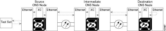
A terminal loopback tests a circuit path as it passes through the SSXC card and loops back from the card with the loopback. Figure 1-2 shows a terminal loopback on an OC-48 card. The test-set traffic enters the optical or Ethernet port and travels through the cross-connect card to the optical port. A terminal loopback turns the signal around before it reaches the LIU and sends it back through the SSXC card to the card. This test verifies that the SSXC card and terminal circuit paths are valid, but does not test the LIU on the optical card.

Figure 1-2 Terminal Loopback Path on an OC-N Card

1.1.3.2  Card Behavior

ONS 15600 terminal port loopbacks can either terminate or bridge the signal. (Some ONS 15600 cards bridge the loopback signal, while others terminate it.)

If a port terminates a terminal loopback signal, the signal only loops back to the originating port and is not transmitted downstream. If the port bridges a loopback signal, the signal loops back to the originating port and is also transmitted downstream.

An OC-N terminal loopback example is shown in Figure 1-3.

Figure 1-3 Terminal Loopback on an OC-N Card with Bridged Signal

The loopback is listed in the Conditions window. For example, the window would list the LPBKTERMINAL condition or LPBKFACILITY condition for a tested port. (The Alarms window would show AS-MT, which indicates that all alarms are suppressed on the port during loopback testing.)

In addition to the Conditions window listing, the following behaviors occur:

If an electrical or optical port is in the OOS-MA,DSBLD service state, it injects an AIS signal upstream and downstream.

When an optical or Ethernet port is placed in the OOS-MA,MT service state before loopback testing, the port clears the AIS signal upstream and downstream unless there is a service-affecting defect that would also cause an AIS signal to be injected. For more information about placing ports into alternate states for testing, refer to the "Change Card Settings" chapter of the Cisco ONS 15600 Procedure Guide.


Caution A lock out of protection must be executed before putting a two-fiber or four-fiber BLSR span into a terminal loopback state. That is, a span lockout of one side (such as the east side) of a two-fiber BLSR is required before operating a facility loopback on the same (east) side of the ring. A span lockout of one protection side (such as the east protection side) of a four-fiber BLSR is required before operating a terminal loopback on the same (east) side working line of the ring. If you do not execute the lockout prior to creating the loopback, the ring can become stuck in an anomalous state after you release the loopback.

1.1.4  Cross-Connect (XC) Loopbacks

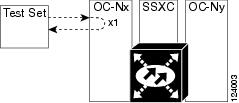
An XC loopback tests a SONET STS circuit path as it passes through a single-shelf cross-connect (SSXC) card and loops back to the port being tested without affecting other traffic on the optical port. Cross-connect loopbacks are less invasive than terminal or facility loopbacks. Testing with facility or terminal loopbacks testing often involve taking down the whole line; however, an XC loopback allows you to create a loopback on any embedded channel at supported payloads of STS-1 granularity and higher. For example, you can place a loopback on a single STS-1, STS-3c, STS-6c, etc. on an optical facility without interrupting the other STS circuits. Figure 1-4 shows the XC loopback path.

Figure 1-4 Cross-Connect Loopback Path on an OC-N Port

This test can be conducted locally or remotely through the CTC interface without on-site personnel. It takes place on an OC-48, OC-192, or ASAP port and tests the traffic path on that STS (or higher) circuit through the port and SSXC. The signal path is similar to a facility loopback.

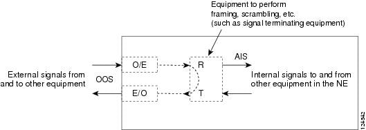
The XC loopback breaks down the existing path and creates a new cross-connect—a hairpin—while the source of the original path is set to inject a line-side AIS-P. The signal path and AIS injection are shown in Figure 1-5.

Figure 1-5 Network Element with SONET Cross-Connect Loopback Function


Note If a terminal or facility loopback exists on a port, you cannot create an XC loopback on it.


Note When testing OC-192 signals with jitter analyzers, be sure to verify with the manufacturer that you are using the most current test equipment. Some test equipment has demonstrated false high jitter readings caused by accumulated jitter dependencies within the test equipment.


1.2  Troubleshooting Optical Circuit Paths With Loopbacks

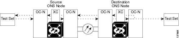
Facility loopbacks or payload loopbacks, terminal loopbacks, and cross-connect (XC) loopback circuits are often used together to test the circuit path through the network or to logically isolate a fault. Performing a loopback test at each point along the circuit path systematically isolates possible points of failure.

The procedures in this section apply to OC-48, OC-192, and ASAP optical ports. (For instructions on ASAP Ethernet ports, go to the "Troubleshooting an Ethernet Circuit Path With Loopbacks" section.) The example in this section tests an OC-N circuit on a three-node BLSR. Using a series of facility, cross-connect, and terminal loopbacks, the example scenario traces the circuit path, tests the possible failure points, and eliminates them. The logical progression contains seven network test procedures:


Note The test sequence for your circuits will differ according to the type of circuit and network topology.


1. A facility (or payload) loopback on the source-node OC-N port

2. A terminal loopback on the source-node OC-N port

3. A cross-connect loopback on the source OC-N port

4. A facility (or payload) loopback on the intermediate-node OC-N port

5. A terminal loopback on the intermediate-node OC-N port

6. A facility (or payload) loopback on the destination-node OC-N port

7. A terminal loopback on the destination-node OC-N port


Note Facility and terminal loopback tests require on-site personnel.


1.2.1  Perform a Facility (Line) Loopback or Payload Loopback on a Source-Node Optical Port

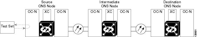
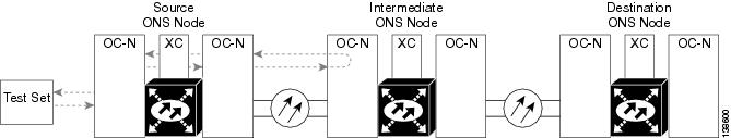
The OC-48 card or ASAP card optical port facility loopback test is performed on the node source port in the network circuit. Likewise for the OC-192 payload loopback. In the testing situation used in this example, the source optical port in the source node. Completing a successful facility loopback on this port isolates the optical port as a possible failure point. Figure 1-6 shows an example of a facility loopback on a circuit source OC-N port.

Figure 1-6 Facility (Line) Loopback on a Circuit Source OC-N Port


Caution Performing a loopback on an in-service circuit is service-affecting.


Note Facility and payload loopbacks require on-site personnel.


Complete the "Create the Facility (Line) Loopback or Payload Loopback on the Source Optical Port" procedure.

Create the Facility (Line) Loopback or Payload Loopback on the Source Optical Port


Step 1 Connect an optical test set to the port you are testing.


Note For specific procedures to use the test set equipment, consult the manufacturer.


Use appropriate cabling to attach the Tx and Rx terminals of the optical test set to the port you are testing. The Tx and Rx terminals connect to the same port. Adjust the test set accordingly. (Refer to manufacturer instructions for test-set use.)

Step 2 In CTC node view, double-click the card to display the card view.

Step 3 Take the port out of service:

a. Clicking the Maintenance > Line (or Maintenance > Optical > Line) tabs.

b. Choose OOS,MT from the Admin State column for the port being tested. If multiple ports are available, select the appropriate row for the desired port.

c. Click Apply.

Step 4 Create the loopback. On the Maintenance tab, click the correct subtab:

For an OC-48 card or OC-192 card, click the Loopback > Port tabs.

For an ASAP card, click the Optical > Loopback > Port tabs.

Step 5 Choose the loopback type:


Note If multiple ports are available, choose the row associated with the correct port and then configure the loopback.


For an OC-48 card, click Facility (Line) in the Loopback Type column.

For an OC-192 card, click Payload in the Loopback Type column.

For an ASAP card, click Facility (Line) in the Loopback Type column.

Step 6 Click Apply.

Step 7 Click Yes in the confirmation dialog box.


Note It is normal for the "LPBKFACILITY (OCN)" condition on page 2-88 or the "LPBKTERMINAL (GIGE)" condition on page 2-89 to appear during loopback setup. The condition clears when you remove the loopback.


Step 8 Complete the "Test and Clear the Facility (Line) Loopback or Payload Loopback Circuit" procedure.


Test and Clear the Facility (Line) Loopback or Payload Loopback Circuit


Step 1 If the test set is not already sending traffic, send test traffic on the loopback circuit.

Step 2 Examine the traffic received by the test set. Look for errors or any other signal information that the test set is capable of indicating.

Step 3 If the test set indicates a good circuit, no further testing is necessary with the facility loopback. Clear the loopback:

a. Click the Maintenance > Loopback > Port (or Maintenance > Optical > Loopback > Port) tabs.

b. Choose the appropriate state (IS; OOS,DSBLD; OOS,MT; IS,AINS) from the Admin State column for the port being tested. If multiple ports are available, select the appropriate row for the desired port. (The new admin state will override the loopback.)

c. Click Apply.

d. Click Yes in the confirmation dialog box.

Step 4 Complete the "Test the Optical Card" procedure.


Test the Optical Card


Step 1 Complete the "Replace an OC-48 Card or OC-192 Card" procedure on page 2-138 for the suspected bad card and replace it with a known-good one.


Caution Removing a card that currently carries traffic on one or more ports can cause a traffic hit. To avoid this, perform an external switch if a switch has not already occurred. See the procedures in the "2.8.2  Protection Switching, Lock Initiation, and Clearing" section on page 2-126. For more information, refer to the "Maintain the Node" chapter of the Cisco ONS 15600 Procedure Guide.

Step 2 Resend test traffic on the loopback circuit with a known-good card installed.

Step 3 If the test set indicates a good circuit, the problem was probably the defective card. Return the defective card to Cisco through the RMA process. Contact Cisco Technical Support (1 800 553-2447).

Step 4 Complete the "Replace an OC-48 Card or OC-192 Card" procedure on page 2-138 for the faulty card.

Step 5 Clear the facility loopback:

Step 6 If the test set indicates a good circuit, no further testing is necessary with the facility or payload loopback. Clear the loopback:

a. Click the Maintenance > Loopback > Port (or Maintenance > Optical > Loopback > Port) tabs.

b. Choose the appropriate state (IS; OOS,DSBLD; OOS,MT; IS,AINS) from the Admin State column for the port being tested. If multiple ports are available, select the appropriate row for the desired port. (The new admin state will override the loopback.)

c. Click Apply.

d. Click Yes in the confirmation dialog box.

Step 7 Complete the "Perform a Terminal (Inward) Loopback on a Source-Node Optical Port" procedure.


1.2.2  Perform a Terminal (Inward) Loopback on a Source-Node Optical Port

The terminal loopback test is only available on ASAP card optical and Ethernet ports. (This section will only address the optical ports; Ethernet ports are covered in Troubleshooting an Ethernet Circuit Path With Loopbacks.) Terminal loopbacks are not available on OC-48 or OC-192 cards.

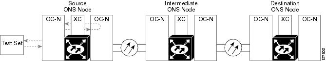
To create a terminal loopback, create a bidirectional circuit originating on the node source optical port and looping back on the node source optical port. You then proceed with the terminal loopback test. Completing a successful terminal loopback to a node source port verifies that the circuit is good to the source port. Figure 1-7 shows an example of a terminal loopback on a source optical port.

Figure 1-7 Terminal (Inward) Loopback on a Source-Node OC-N Port


Caution Performing a loopback on an in-service circuit is service-affecting.


Note Terminal loopbacks require on-site personnel.


Complete the "Create the Terminal (Inward) Loopback on a Source-Node Optical Port" procedure.

Create the Terminal (Inward) Loopback on a Source-Node Optical Port


Step 1 Connect an optical test set to the ASAP card optical port you are testing:


Note For specific procedures to use the test set equipment, consult the manufacturer.


a. If you just completed the "Perform a Facility (Line) Loopback or Payload Loopback on a Source-Node Optical Port" procedure for an ASAP card optical port, leave the optical test set hooked up.

b. If you are starting the current procedure without the optical test set hooked up to the source optical port, use appropriate cabling to attach the Tx and Rx terminals of the optical test set to the port you are testing. Both Tx and Rx connect to the same port.

c. Adjust the test set accordingly. (Refer to manufacturer instructions for test-set use.)

Step 2 Use CTC to set up the terminal loopback on the test port:

a. In node view, click the Circuits tab and click Create.

b. In the Circuit Creation dialog box, choose the type, such as STS, and number, such as 1.

c. Click Next.

d. In the next Circuit Creation dialog box, give the circuit an easily identifiable name such as Opt1toOpt2.

e. Leave the Bidirectional check box checked.

f. Click Next.

g. In the Circuit Creation source dialog box, select the same Node, card Slot, Port, and STS (or VT) where the test set is connected.

h. Click Next.

i. In the Circuit Creation destination dialog box, use the same Node, card Slot, Port, and STS (or VT) used for the source dialog box.

j. Click Next.

k. In the Circuit Creation circuit routing preferences dialog box, leave all defaults. Click Finish.

Step 3 Confirm that the newly created circuit appears on the Circuits tab list as a two-way circuit.


Note It is normal for the "LPBKTERMINAL (OCN)" condition on page 2-89 to appear during a loopback setup. The condition clears when you remove the loopback.


Step 4 Create the terminal loopback on the destination port being tested:

a. In node view, double-click the ASAP card.

b. Click the Maintenance > Optical > Loopback > Port tabs.

c. Select OOS,MT from the Admin State column. If there are multiple available circuits, select the row appropriate for the desired port.

d. Select Terminal (Inward) from the Loopback Type column.

e. Click Apply.

f. Click Yes in the confirmation dialog box.

Step 5 Complete the "Test and Clear the Terminal Loopback Circuit" procedure.


Test and Clear the Terminal Loopback Circuit


Step 1 If the test set is not already sending traffic, send test traffic on the loopback circuit.

Step 2 Examine the test traffic being received by the test set. Look for errors or any other signal information that the test set is capable of indicating.

Step 3 If the test set indicates a good circuit, no further testing is necessary on the loopback circuit. Clear the terminal loopback state on the port:

a. Double-click the ASAP in the source node.

a. Click the Maintenance > Optical > Loopback > Port tabs.

b. Choose the appropriate state (IS; OOS,DSBLD; OOS,MT; IS,AINS) from the Admin State column for the port being tested. If multiple ports are available, select the appropriate row for the desired port. (The new admin state will override the loopback.)

c. Click Apply.

d. Click Yes in the confirmation dialog box.

Step 4 Clear the terminal loopback circuit:

a. Click the Circuits tab.

b. Choose the loopback circuit being tested.

c. Click Delete.

d. Click Yes in the Delete Circuits dialog box. Do not check any check boxes.

Step 5 Complete the "Test the ASAP Card" procedure.


Test the ASAP Card


Step 1 Determine whether you are experiencing trouble on a single SFP (PPM), on all PPMs within a 4PIO (PIM), or on all 4PIO used in that ASAP card. If there is only partial failure, you may be able to replace this part rather than the entire card.

Step 2 If the errors are being observed on one port but not all ports of the ASAP, you may only need to replace that SFP (PPM). Remove the errored SFP (PPM) and replace it with a known-good SFP (PPM) by completing the procedures for this in the "Install Cards and Fiber-Optic Cable" chapter of the Cisco ONS 15600 Procedure Guide.

Step 3 If all SFPs (PPMs) on a particular 4PIO (PIM) are experiencing problems, the 4PIO (PIM) is indicated. Remove this 4PIO (PIM) and replace it with a known-good one using the procedures for this in the "Install Cards and Fiber-Optic Cable" chapter of the Cisco ONS 15600 Procedure Guide.

Step 4 If the trouble still is not located, complete the "Replace an OC-48 Card or OC-192 Card" procedure on page 2-138 for the suspected bad ASAP card and replace it with a known-good one.

Step 5 Resend test traffic on the loopback circuit with a known-good card.

Step 6 If the test set indicates a good circuit, the problem was probably the defective card. Return the defective card to Cisco through the RMA process. Contact Cisco Technical Support (1 800 553-2447).

Step 7 Complete the "Replace an OC-48 Card or OC-192 Card" procedure on page 2-138 for the defective card.

Step 8 Clear the terminal loopback on the port before testing the next segment of the network circuit path:

a. Double-click the ASAP card in the source node with the terminal loopback.

a. Click the Maintenance > Optical > Loopback > Port tabs.

b. Choose the appropriate state (IS; OOS,DSBLD; OOS,MT; IS,AINS) from the Admin State column for the port being tested. If multiple ports are available, select the appropriate row for the desired port. (The new admin state will override the loopback.)

c. Click Apply.

d. Click Yes in the confirmation dialog box.

Step 9 Clear the terminal loopback circuit before testing the next segment of the network circuit path:

a. Click the Circuits tab.

b. Choose the loopback circuit being tested.

c. Click Delete.

d. Click Yes in the Delete Circuits dialog box. Do not check any check boxes.

Step 10 Complete the "Perform an XC Loopback on the Source Optical Port" procedure.


1.2.3  Perform an XC Loopback on the Source Optical Port


Note This procedure is performed from an OC-N card or ASAP card optical port to test the cross-connect circuit connection.


Note You can perform an XC loopback on either the circuit source working or the protect port of a 1+1 protection group.


Note XC loopbacks do not require on-site personnel.


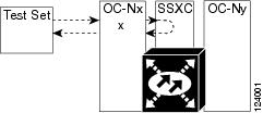
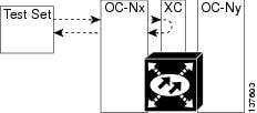
The XC loopback test is available for OC-48, OC-192, and ASAP cards and occurs on an optical circuit transiting the SSXC card in a network circuit. Completing a successful XC loopback from an optical port through the SSXC card eliminates the SSXC card as the source of trouble for a faulty circuit. Figure 1-8 shows an example of an XC loopback path on a source OC-N port.

Figure 1-8 XC Loopback on a Source OC-N Port

Complete the "Create the XC Loopback on the Source-Node Optical Port" procedure.

Create the XC Loopback on the Source-Node Optical Port


Step 1 Connect an optical test set to the optical port you are testing:


Note For specific procedures to use the test set equipment, consult the manufacturer.


a. If you just completed the "Perform a Terminal (Inward) Loopback on a Source-Node Optical Port" procedure, leave the optical test set hooked up to the source-node port.

b. If you are starting the current procedure without the optical test set hooked up to the source port, use appropriate cabling to attach the Tx and Rx terminals of the optical test set to the port you are testing. The Tx and Rx terminals connect to the same port.

Step 2 Adjust the test set accordingly. (Refer to manufacturer instructions for test-set use.)

Step 3 Use CTC to put the circuit being tested out of service:

a. In node view, click the Circuits tab.

b. Click the circuit and then click Edit.

c. In the Edit Circuit dialog box, click the State tab.

d. Choose OOS,MT from the Target Circuit Admin State drop-down list.

e. Click Apply.

f. Click Yes in the confirmation dialog box.

Step 4 Use CTC to set up the XC loopback on the circuit being tested:

a. In node view, double-click the OC-N card to display the card view.

b. Click the Maintenance > Loopback > SONET STS tabs (or Maintenance > Optical > Loopback > SONET STS tabs).

c. Click the check box in the XC Loopback column for the port being tested.

d. Click Apply.

e. Click Yes in the confirmation dialog box.

Step 5 Complete the "Test and Clear the XC Loopback Circuit" procedure.


Test and Clear the XC Loopback Circuit


Step 1 If the test set is not already sending traffic, send test traffic on the loopback circuit.

Step 2 Examine the test traffic received by the test set. Look for errors or any other signal information that the test set is capable of indicating.

Step 3 If the test set indicates a good circuit, no further testing is necessary with the cross-connect. Clear the XC loopback:

a. In card view, click the Maintenance > Loopback > SONET STS tabs (or Maintenance > Optical > Loopback > SONET STS tabs).

b. Uncheck the check box in the XC Loopback column for the circuit being tested.

c. Click Apply.

d. Click Yes in the confirmation dialog box.

Step 4 Complete the "Test the Alternate SSXC Card" procedure.


Test the Alternate SSXC Card


Step 1 Do a manual data copy switch of the SSXC cards before retesting the XC loopback circuit:

a. In node view, select the Maintenance > Preferred Copy tabs.

b. In the Set Preferred drop-down menu, select the alternate copy. (For example, if Copy B is preferred and in use, select Copy A.)


Note Note CTC Copy A refers to the SSXC card in Slot 6. Copy B refers to the SSXC card in Slot 8. Either copy might be chosen as the preferred copy SSXC. The other SSXC is called the alternate SSXC in this chapter.


c. Click Apply.

d. Click Yes in the confirmation dialog box.


Note If you attempt a preferred copy switch and the switch is unsuccessful, a problem is present with the alternate SSXC.


e. Click Refresh until the tab shows that the alternate copy you selected is now the preferred copy. The Currently Used field will show the newly-selected preferred copy.

Step 2 Resend test traffic on the XC loopback circuit.

The test traffic now travels through the alternate cross-connect card.

Step 3 If the test set indicates a faulty circuit, assume the cross-connect card is not causing the problem. Clear the XC loopback circuit:

a. Click the Circuits tab.

b. Choose the XC loopback circuit being tested.

c. Click Delete.

d. Click Yes in the Delete Circuits dialog box. Do not check any check boxes.

e. Confirm that the XC loopback circuit is deleted from the Circuits tab list. If the test set indicates a good circuit, the problem might be a defective cross-connect card.

Step 4 To confirm a defective preferred cross-connect card, complete the "Retest the Preferred SSXC Card" procedure.


Retest the Preferred SSXC Card


Step 1 Do a manual data copy switch of the SSXC cards before retesting the loopback circuit:

a. In node view, select the Maintenance > Preferred Copy tabs.

b. In the Set Preferred drop-down menu, select the alternate copy. (For example, if Copy B is preferred and in use, select Copy A.)

c. Click Apply.

d. Click Yes on the confirmation dialog box.


Note If you attempt a preferred copy switch and the switch is unsuccessful, a problem is present with the alternate SSXC.


e. Click Refresh until the tab shows that the alternate copy you selected is now the preferred copy. The Currently Used field will show the newly-selected preferred copy.

Step 2 Resend test traffic on the loopback circuit.

Step 3 If the test set indicates a faulty circuit, the problem is probably the defective card. Return the defective card to Cisco through the RMA process. Contact Cisco Technical Support (1 800 553-2447) and proceed to Step 4. If the circuit is not shown to be faulty and the card is not shown to be defective, you are finished with testing.

Step 4 Complete the "Replace an SSXC Card" procedure on page 2-137 for the defective card. Perform Step 5.

Step 5 If the test set indicates a good circuit, the cross-connect card might have had a temporary problem that was cleared by the side switch. Clear the XC loopback circuit:

a. Click the Circuits tab.

b. Choose the XC loopback circuit being tested.

c. Click Delete.

d. Click Yes in the Delete Circuits dialog box. Do not check any check boxes.

Step 6 Complete the "Perform a Facility (Line) Loopback or Payload Loopback on an Intermediate-Node Optical Port" procedure.


1.2.4  Perform a Facility (Line) Loopback or Payload Loopback on an Intermediate-Node Optical Port

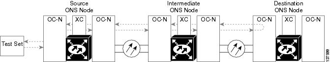
Performing an OC-48 or ASAP card optical facility loopback (or OC-192 payload loopback) on an intermediate port isolates whether this node is causing circuit failure. In the situation shown in Figure 1-9, the test is being performed on an intermediate OC-N port.

Figure 1-9 Facility (Line) Loopback Path to an Intermediate-Node OC-N Port


Caution Performing a loopback on an in-service circuit is service-affecting.


Note Facility and payload loopbacks require on-site personnel.


Complete the "Create a Facility (Line) Loopback or Payload Loopback on an Intermediate-Node Optical Port" procedure.

Create a Facility (Line) Loopback or Payload Loopback on an Intermediate-Node Optical Port


Step 1 Connect an optical test set to the port you are testing. If you are starting the current procedure without the optical test set hooked up to the source port port, use appropriate cabling to attach the Tx and Rx terminals of the optical test set to the port you are testing. Both Tx and Rx connect to the same port.

For specific procedures to use the test set equipment, consult the manufacturer.

Step 2 Adjust the test set accordingly. (Refer to manufacturer instructions for test-set use.)

Step 3 Use CTC to set up the facility loopback on the test port:

a. In node view, click the Circuits tab and click Create.

b. In the Circuit Creation dialog box, choose the type, such as STS, and number, such as 1.

c. Click Next.

d. In the next Circuit Creation dialog box, give the circuit an easily identifiable name such as Opt1toOpt3.

e. Leave the Bidirectional check box checked.

f. Click Next.

g. In the Circuit Creation source dialog box, select the same Node, card Slot, Port, and STS (or VT) where the test set is connected.

h. Click Next.

i. In the Circuit Creation destination dialog box, use the same Node, card Slot, Port, and STS (or VT) used for the source dialog box.

j. Click Next.

k. In the Circuit Creation circuit routing preferences dialog box, leave all defaults. Click Finish.

Step 4 Confirm that the newly created circuit appears on the Circuits tab list as a two-way circuit.


Note It is normal for the "LPBKFACILITY (OCN)" condition on page 2-88 to appear during a loopback setup. The condition clears when you remove the loopback.


Step 5 Create the facility loopback on the intermediate port being tested:

a. Go to the node view of the intermediate node:

Choose View > Go To Other Node from the menu bar.

Choose the node from the drop-down list in the Select Node dialog box and click OK.

b. In node view, double-click the intermediate-node card that requires the loopback.

c. Click the Maintenance > Loopback > Port tabs (or Maintenance > Optical > Loopback > Port tabs).

d. Select OOS,MT from the Admin State column. If multiple ports are available, select the row appropriate for the desired port.

e. For an OC-48 card or ASAP card optical port, select Facility (Line) from the Loopback Type column. For an OC-192 card, select Payload. If multiple ports are available, select the row appropriate for the desired port.

f. Click Apply.

g. Click Yes in the confirmation dialog box.

Step 6 Complete the "Test and Clear the Facility (Line) Loopback or Payload Loopback Circuit" procedure.


Test and Clear the Facility (Line) Loopback or Payload Loopback Circuit


Step 1 If the test set is not already sending traffic, send test traffic on the loopback circuit.

Step 2 Examine the traffic received by the test set. Look for errors or any other signal information that the test set is capable of indicating.

Step 3 If the test set indicates a good circuit, no further testing is necessary with the facility loopback. Clear the facility loopback from the port:

a. Click the Maintenance > Loopback > Port tabs (or Maintenance > Optical > Loopback > Port tabs).

b. Choose None from the Loopback Type column for the port being tested.

c. Choose the appropriate state (IS; OOS,DSBLD; OOS,MT; IS,AINS) from the Admin State column for the port being tested.

d. Click Apply.

e. Click Yes in the confirmation dialog box.

Step 4 Clear the loopback circuit:

a. Click the Circuits tab.

b. Choose the loopback circuit being tested.

c. Click Delete.

d. Click Yes in the Delete Circuits dialog box. Do not check any check boxes.

Step 5 Complete the "Test the Optical Card" procedure.


Test the Optical Card


Step 1 Complete the "Replace an OC-48 Card or OC-192 Card" procedure on page 2-138 for the suspected bad OC-N or ASAP card and replace it with a known-good one.


Caution Removing a card that currently carries traffic on one or more ports can cause a traffic hit. To avoid this, perform an external switch if a switch has not already occurred. See the procedures in the "2.8.2  Protection Switching, Lock Initiation, and Clearing" section on page 2-126. For more information, refer to the "Maintain the Node" chapter of the Cisco ONS 15600 Procedure Guide.

Step 2 Resend test traffic on the loopback circuit with a known-good card installed.

Step 3 If the test set indicates a good circuit, the problem was probably the defective card. Return the defective card to Cisco through the RMA process. Contact Cisco Technical Support (1 800 553-2447).

Step 4 Complete the "Replace an OC-48 Card or OC-192 Card" procedure on page 2-138 for the faulty card.

Step 5 Clear the facility loopback from the port:

a. Click the Maintenance > Loopback > Port tabs (or Maintenance > Optical > Loopback > Port tabs).

b. Choose None from the Loopback Type column for the port being tested.

c. Choose the appropriate state (IS; OOS,DSBLD; OOS,MT; IS,AINS) from the Admin State column for the port being tested.

d. Click Apply.

e. Click Yes in the confirmation dialog box.

Step 6 Clear the loopback circuit:

a. Click the Circuits tab.

b. Choose the loopback circuit being tested.

c. Click Delete.

d. Click Yes in the Delete Circuits dialog box. Do not check any check boxes.

Step 7 Complete the "Perform a Facility (Line) Loopback or Payload Loopback on a Destination-Node Optical Port" procedure.


1.2.5  Perform a Facility (Line) Loopback or Payload Loopback on a Destination-Node Optical Port

You perform a facility loopback test at the destination port to determine whether this local port is the source of circuit trouble. The example in Figure 1-10 shows a facility loopback being performed on a destination-node OC-N port.

Figure 1-10 Facility (Line) Loopback Path to a Destination-Node OC-N Port


Caution Performing a loopback on an in-service circuit is service-affecting.


Note Facility loopbacks require on-site personnel.


Complete the "Create the Facility (Line) Loopback or Payload Loopback on a Destination-Node Optical Port" procedure.

Create the Facility (Line) Loopback or Payload Loopback on a Destination-Node Optical Port


Step 1 Connect an optical test set to the OC-N or ASAP optical port you are testing. If you are starting the current procedure without the optical test set hooked up to the source port, use appropriate cabling to attach the Tx and Rx terminals of the optical test set to the port you are testing. Both Tx and Rx connect to the same port.


Note For specific procedures to use the test set equipment, consult the manufacturer.


Step 2 Adjust the test set accordingly. (Refer to manufacturer instructions for test-set use.)

Step 3 Use CTC to set up the facility circuit on the test port:

a. In node view, click the Circuits tab and click Create.

b. In the Circuit Creation dialog box, choose the type, such as STS, and number, such as 1.

c. Click Next.

d. In the next Circuit Creation dialog box, give the circuit an easily identifiable name such as Opt1toOpt5.

e. Leave the Bidirectional check box checked.

f. Click Next.

g. In the Circuit Creation source dialog box, select the same Node, card Slot, Port, and STS (or VT) where the test set is connected.

h. Click Next.

i. In the Circuit Creation destination dialog box, use the same Node, card Slot, Port, and STS (or VT) used for the source dialog box.

j. Click Next.

k. In the Circuit Creation circuit routing preferences dialog box, leave all defaults. Click Finish.

Step 4 Confirm that the newly created circuit appears on the Circuits tab list as a two-way circuit.


Note It is normal for the "LPBKFACILITY (OCN)" condition on page 2-88 to appear during a loopback setup. The condition clears when you remove the loopback.


Step 5 Create the facility loopback on the destination port being tested:

a. Go to the node view of the destination node:

Choose View > Go To Other Node from the menu bar.

Choose the node from the drop-down list in the Select Node dialog box and click OK.

b. In node view, double-click the card that requires the loopback.

c. Click the Maintenance > Loopback > Port tabs (or Maintenance > Optical > Loopback > Port tabs).

d. Select OOS,MT from the Admin State column. If multiple ports are available, select the row appropriate for the desired port.

e. For an ASAP card or OC-48 card, select Facility (Line) from the Loopback Type column. For an OC-192 card, select Payload. If multiple ports are available, select the row appropriate for the desired port.

f. Click Apply.

g. Click Yes in the confirmation dialog box.

Step 6 Complete the "Test and Clear the Optical Facility (Line) Loopback or Payload Loopback Circuit" procedure.


Test and Clear the Optical Facility (Line) Loopback or Payload Loopback Circuit


Step 1 If the test set is not already sending traffic, send test traffic on the loopback circuit.

Step 2 Examine the traffic received by the test set. Look for errors or any other signal information that the test set is capable of indicating.

Step 3 If the test set indicates a good circuit, no further testing is necessary with the facility loopback. Clear the facility loopback from the port:

a. Click the Maintenance > Loopback > Port tabs (or Maintenance > Optical > Loopback > Port tabs).

b. Choose None from the Loopback Type column for the port being tested.

c. Choose the appropriate state (IS; OOS,DSBLD; OOS,MT; IS,AINS) from the Admin State column for the port being tested.

d. Click Apply.

e. Click Yes in the confirmation dialog box.

Step 4 Clear the loopback circuit:

a. Click the Circuits tab.

b. Choose the loopback circuit being tested.

c. Click Delete.

d. Click Yes in the Delete Circuits dialog box. Do not check any check boxes.

Step 5 Complete the "Test the Optical Card" procedure.


Test the Optical Card


Step 1 Complete the "Replace an OC-48 Card or OC-192 Card" procedure on page 2-138 for the suspected bad OC-N or ASAP card and replace it with a known-good one.


Caution Removing a card that currently carries traffic on one or more ports can cause a traffic hit. To avoid this, perform an external switch if a switch has not already occurred. See the procedures in the "2.8.2  Protection Switching, Lock Initiation, and Clearing" section on page 2-126. For more information, refer to the "Maintain the Node" chapter of the Cisco ONS 15600 Procedure Guide.

Step 2 Resend test traffic on the loopback circuit with a known-good card installed.

Step 3 If the test set indicates a good circuit, the problem was probably the defective card. Return the defective card to Cisco through the RMA process. Contact Cisco Technical Support (1 800 553-2447).

Step 4 Complete the "Replace an OC-48 Card or OC-192 Card" procedure on page 2-138 for the faulty card.

Step 5 Clear the loopback on the port:

a. Click the Maintenance > Loopback > Port tabs (or Maintenance > Optical > Loopback > Port tabs).

b. Choose None from the Loopback Type column for the port being tested.

c. Choose the appropriate state (IS; OOS,DSBLD; OOS,MT; IS,AINS) from the Admin State column for the port being tested.

d. Click Apply.

e. Click Yes in the confirmation dialog box.

Step 6 Clear the loopback circuit:

a. Click the Circuits tab.

b. Choose the loopback circuit being tested.

c. Click Delete.

d. Click Yes in the Delete Circuits dialog box. Do not check any check boxes.

Step 7 Complete the "Perform a Terminal Loopback on a Destination-Node Optical Port" procedure.


1.2.6  Perform a Terminal Loopback on a Destination-Node Optical Port

The terminal loopback at the destination-node ASAP card optical port is the final local hardware error elimination in the circuit troubleshooting process. If this test is completed successfully, you have verified that the circuit is good up to the destination port.


Caution Performing a loopback on an in-service circuit is service-affecting.


Note OC-48 and OC-192 cards are not capable of terminal loopbacks.


Note Terminal loopbacks require on-site personnel.


Complete the "Create the Terminal Loopback on a Destination-Node Optical Port" procedure.

Create the Terminal Loopback on a Destination-Node Optical Port


Step 1 Connect an optical test set to the ASAP card optical port you are testing: If you are starting the current procedure without the optical test set hooked up to the source port, use appropriate cabling to attach the Tx and Rx terminals of the optical test set to the port you are testing. Both Tx and Rx connect to the same port.


Note For specific procedures to use the test set equipment, consult the manufacturer.


Step 2 Adjust the test set accordingly. (Refer to manufacturer instructions for test-set use.)

Step 3 Use CTC to set up the terminal loopback on the test port:

a. In node view, click the Circuits tab and click Create.

b. In the Circuit Creation dialog box, choose the type, such as STS, and number, such as 1.

c. Click Next.

d. In the next Circuit Creation dialog box, give the circuit an easily identifiable name such as Opt1toOpt6.

e. Leave the Bidirectional check box checked.

f. Click Next.

g. In the Circuit Creation source dialog box, select the same Node, card Slot, Port, and STS (or VT) where the test set is connected.

h. Click Next.

i. In the Circuit Creation destination dialog box, use the same Node, card Slot, Port, and STS (or VT) used for the source dialog box.

j. Click Next.

k. In the Circuit Creation circuit routing preferences dialog box, leave all defaults. Click Finish.

Step 4 Confirm that the newly created circuit appears on the Circuits tab list as a two-way circuit.


Note It is normal for the "LPBKTERMINAL (OCN)" condition on page 2-89 to appear during a loopback setup. The condition clears when you remove the loopback.


Step 5 Create the terminal loopback on the destination port being tested:

a. Go to the node view of the destination node:

Choose View > Go To Other Node from the menu bar.

Choose the node from the drop-down list in the Select Node dialog box and click OK.

b. In node view, double-click the card that requires the loopback.

c. Click the Maintenance > Optical > Loopback > Port tab.

d. Select OOS,MT from the Admin State column. If multiple ports are available, select the row appropriate for the desired port.

e. Select Terminal (Inward) from the Loopback Type column. If multiple ports are available, select the row appropriate for the desired port.

f. Click Apply.

g. Click Yes in the confirmation dialog box.

Step 6 Complete the "Test and Clear the Optical Terminal Loopback Circuit" procedure.


Test and Clear the Optical Terminal Loopback Circuit


Step 1 If the test set is not already sending traffic, send test traffic on the loopback circuit.

Step 2 Examine the test traffic being received by the test set. Look for errors or any other signal information that the test set is capable of indicating.

Step 3 If the test set indicates a good circuit, no further testing is necessary on the loopback circuit. Clear the terminal loopback from the port:

a. Double-click the destination-node ASAP card with the terminal loopback.

b. Click the Maintenance > Optical > Loopback > Port tab.

c. Select None from the Loopback Type column for the port being tested.

d. Select the appropriate state (IS; OOS,DSBLD; OOS,MT; IS,AINS) in the Admin State column for the port being tested.

e. Click Apply.

f. Click Yes in the confirmation dialog box.

Step 4 Clear the terminal loopback circuit:

a. Click the Circuits tab.

b. Choose the loopback circuit being tested.

c. Click Delete.

d. Click Yes in the Delete Circuits dialog box. Do not check any check boxes.

The entire circuit path has now passed its comprehensive series of loopback tests. This circuit qualifies to carry live traffic.

Step 5 If the test set indicates a faulty circuit, the problem might be a faulty card.

Step 6 Complete the "Test the ASAP Card" procedure.


Test the ASAP Card


Step 1 Determine whether you are experiencing trouble on a single SFP (PPM), on all PPMs within a 4PIO (PIM), or on all 4PIO used in that ASAP card. If there is only partial failure, you may be able to replace this part rather than the entire card.

Step 2 If the errors are being observed on one port but not all ports of the ASAP, you may only need to replace that SFP (PPM). Remove the errored SFP (PPM) and replace it with a known-good SFP (PPM) by completing the procedures for this in the "Install Cards and Fiber-Optic Cable" chapter of the Cisco ONS 15600 Procedure Guide.

Step 3 If all SFPs (PPMs) on a particular 4PIO (PIM) are experiencing problems, the 4PIO (PIM) is indicated. Remove this 4PIO (PIM) and replace it with a known-good one using the procedures for this in the "Install Cards and Fiber-Optic Cable" chapter of the Cisco ONS 15600 Procedure Guide.

Step 4 If the trouble still is not located, complete the "Replace an OC-48 Card or OC-192 Card" procedure on page 2-138 for the suspected bad ASAP card and replace it with a known-good one.


Caution Removing a card that currently carries traffic on one or more ports can cause a traffic hit. To avoid this, perform an external switch if a switch has not already occurred. See the procedures in the "2.8.2  Protection Switching, Lock Initiation, and Clearing" section on page 2-126. For more information, refer to the "Maintain the Node" chapter of the Cisco ONS 15600 Procedure Guide.

Step 5 Resend test traffic on the loopback circuit with a known-good card.

Step 6 If the test set indicates a good circuit, the problem was probably the defective card. Return the defective card to Cisco through the RMA process. Contact Cisco Technical Support (1 800 553-2447).

Step 7 Complete the "Replace an OC-48 Card or OC-192 Card" procedure on page 2-138 for the defective card.

Step 8 Clear the terminal loopback on the port:

a. Double-click the source-node card with the terminal loopback.

b. Click the Maintenance > Optical > Loopback > Port tabs.

c. Select None from the Loopback Type column for the port being tested.

d. Select the appropriate state (IS; OOS,DSBLD; OOS,MT; IS,AINS) in the Admin State column for the port being tested.

e. Click Apply.

f. Click Yes in the confirmation dialog box.

Step 9 Clear the terminal loopback circuit:

a. Click the Circuits tab.

b. Choose the loopback circuit being tested.

c. Click Delete.

d. Click Yes in the Delete Circuits dialog box. Do not check any check boxes.

The entire optical circuit path has now passed its comprehensive series of loopback tests. This circuit qualifies to carry live traffic.


1.3  Troubleshooting an Ethernet Circuit Path With Loopbacks

Facility (line) loopbacks and terminal loopbacks are often used together to test the circuit path through the network or to logically isolate a fault. Performing a loopback test at each point along the circuit path systematically isolates possible points of failure.

You can use these procedures only on the ASAP card Ethernet ports in the ONS 15600 system. The example in this section tests an Ethernet circuit on a three-node BLSR. Using a series of facility loopbacks and terminal loopbacks, the example scenario traces the circuit path, tests the possible failure points, and eliminates them. The logical progression contains six network test procedures:


Note The test sequence for your circuits will differ according to the type of circuit and network topology.


1. A facility loopback on the source-node Ethernet port

2. A terminal loopback on the source-node Ethernet port

3. A facility loopback on the intermediate-node Ethernet port

4. A terminal loopback on the intermediate-node Ethernet port

5. A facility loopback on the destination-node Ethernet port

6. A terminal loopback on the destination-node Ethernet port


Note Facility and terminal loopback tests require on-site personnel.


1.3.1  Perform a Facility (Line) Loopback on a Source-Node Ethernet Port

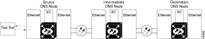
The facility loopback test is performed on the node source port in the network circuit. In the testing situation used in this example, the source is an ASAP Ethernet port in the source node. Completing a successful facility loopback on this port isolates the port as a possible failure point. Figure 1-11 shows an example of a facility loopback on a circuit source Ethernet port.


Note Facility loopbacks require on-site personnel.


Figure 1-11 Facility (Line) Loopback on a Circuit Source Ethernet Port


Caution Performing a loopback on an in-service circuit is service-affecting.

Complete the "Create the Facility (Line) Loopback on the Source-Node Ethernet Port" procedure.

Create the Facility (Line) Loopback on the Source-Node Ethernet Port


Step 1 Connect an optical test set to the ASAP Ethernet port you are testing.


Note For specific procedures to use the test set equipment, consult the manufacturer.


Use appropriate cabling to attach the Tx and Rx terminals of the optical test set to the port you are testing. The Tx and Rx terminals connect to the same port.

Step 2 Adjust the test set accordingly. (Refer to manufacturer instructions for test-set use.)

Step 3 In CTC node view, double-click the card to display the card view.

Step 4 Click the Maintenance > Ethernet > Loopback > Port tabs.

Step 5 Choose OOS,MT from the Admin State column for the port being tested. If multiple ports are available, select the appropriate row for the desired port.

Step 6 Choose Facility (Line) from the Loopback Type column for the port being tested. If multiple ports are available, select the appropriate row for the desired port.

Step 7 Click Apply.

Step 8 Click Yes in the confirmation dialog box.


Note It is normal for the "LPBKFACILITY (GIGE)" condition on page 2-87 to appear during loopback setup. The condition clears when you remove the loopback.


Step 9 Complete the "Test and Clear the Facility (Line) Loopback Circuit" procedure.


Test and Clear the Facility (Line) Loopback Circuit


Step 1 If the test set is not already sending traffic, send test traffic on the loopback circuit.

Step 2 Examine the traffic received by the test set. Look for errors or any other signal information that the test set is capable of indicating.

Step 3 If the test set indicates a good circuit, no further testing is necessary with the facility loopback. Clear the facility loopback:

a. Click the Maintenance > Ethernet > Loopback > Port tab.

b. Choose None from the Loopback Type column for the port being tested.

c. Choose the appropriate state (IS; OOS,DSBLD; OOS,MT) from the Admin State column for the port being tested.

d. Click Apply.

e. Click Yes in the confirmation dialog box.

Step 4 Complete the "Test the ASAP Card" procedure.


Test the ASAP Card


Step 1 Determine whether you are experiencing trouble on a single SFP (PPM), on all PPMs within a 4PIO (PIM), or on all 4PIO used in that ASAP card. If there is only partial failure, you may be able to replace this part rather than the entire card.

Step 2 If the errors are being observed on one port but not all ports of the ASAP, you may only need to replace that SFP (PPM). Remove the errored SFP (PPM) and replace it with a known-good SFP (PPM) by completing the procedures for this in the "Install Cards and Fiber-Optic Cable" chapter of the Cisco ONS 15600 Procedure Guide.

Step 3 If all SFPs (PPMs) on a particular 4PIO (PIM) are experiencing problems, the 4PIO (PIM) is indicated. Remove this 4PIO (PIM) and replace it with a known-good one using the procedures for this in the "Install Cards and Fiber-Optic Cable" chapter of the Cisco ONS 15600 Procedure Guide.

Step 4 If the trouble still is not located, complete the "Replace an OC-48 Card or OC-192 Card" procedure on page 2-138 for the suspected bad ASAP card and replace it with a known-good one.


Caution Removing a card that currently carries traffic on one or more ports can cause a traffic hit. To avoid this, perform an external switch if a switch has not already occurred. See the procedures in the "2.8.2  Protection Switching, Lock Initiation, and Clearing" section on page 2-126. For more information, refer to the "Maintain the Node" chapter of the Cisco ONS 15600 Procedure Guide.

Step 5 Resend test traffic on the loopback circuit with a known-good card installed.

Step 6 If the test set indicates a good circuit, the problem was probably the defective card. Return the defective card to Cisco through the RMA process. Contact Cisco Technical Support (1 800 553-2447).

Step 7 Complete the "Replace an OC-48 Card or OC-192 Card" procedure on page 2-138 for the faulty card.

Step 8 Clear the facility loopback:

a. Click the Maintenance > Ethernet > Loopback > Port tab.

b. Choose None from the Loopback Type column for the port being tested.

c. Choose the appropriate state (IS; OOS,DSBLD; OOS,MT) from the Admin State column for the port being tested.

d. Click Apply.

e. Click Yes in the confirmation dialog box.

Step 9 Complete the "Perform a Terminal (Inward) Loopback on a Source-Node Ethernet Port" procedure.


1.3.2  Perform a Terminal (Inward) Loopback on a Source-Node Ethernet Port

The terminal loopback test is performed on the node source Ethernet port. For the circuit in this example, it is the source Ethernet port in the source node. You first create a bidirectional circuit that starts on the node destination Ethernet port and loops back on the node source Ethernet port.You then proceed with the terminal loopback test. Completing a successful terminal loopback to a node source port verifies that the circuit is good to the source port.


Caution Performing a loopback on an in-service circuit is service-affecting.


Note Terminal loopbacks require on-site personnel.


Complete the "Create the Terminal (Inward) Loopback on a Source-Node Ethernet Port" procedure.

Create the Terminal (Inward) Loopback on a Source-Node Ethernet Port


Step 1 Connect an optical test set to the ASAP card Ethernet port you are testing:


Note For specific procedures to use the test set equipment, consult the manufacturer.


a. If you just completed the "Perform a Facility (Line) Loopback on a Source-Node Ethernet Port" procedure, leave the optical test set hooked up to the Ethernet port in the source node.

b. If you are starting the current procedure without the optical test set hooked up to the source Ethernet port, use appropriate cabling to attach the Tx and Rx terminals of the optical test set to the port you are testing. Both Tx and Rx connect to the same port.

Step 2 Adjust the test set accordingly. (Refer to manufacturer instructions for test-set use.)

Step 3 Use CTC to set up the terminal loopback on the test port:

a. In node view, click the Circuits tab and click Create.

b. In the Circuit Creation dialog box, choose the type, such as STS, and number, such as 1.

c. Click Next.

d. In the next Circuit Creation dialog box, give the circuit an easily identifiable name such as Eth1toEth2.

e. Leave the Bidirectional check box checked.

f. Click Next.

g. In the Circuit Creation source dialog box, select the same Node, card Slot, Port, and STS (or VT) where the test set is connected.

h. Click Next.

i. In the Circuit Creation destination dialog box, use the same Node, card Slot, Port, and STS (or VT) used for the source dialog box.

j. Click Next.

k. In the Circuit Creation circuit routing preferences dialog box, leave all defaults. Click Finish.

Step 4 Confirm that the newly created circuit appears on the Circuits tab list as a two-way circuit.


Note It is normal for the "LPBKTERMINAL (GIGE)" condition on page 2-89 to appear during a loopback setup. The condition clears when you remove the loopback.


Step 5 Create the terminal loopback on the destination port being tested:

a. In node view, double-click the card that requires the loopback, such as the ASAP card in the source node.

b. Click the Maintenance > Ethernet > Loopback > Port tab.

c. Select OOS,MT from the Admin State column. If multiple ports are available, select the row appropriate for the desired port.

d. Select Terminal (Inward) from the Loopback Type column. If multiple ports are available, select the row appropriate for the desired port.

e. Click Apply.

f. Click Yes in the confirmation dialog box.

Step 6 Complete the "Test and Clear the Ethernet Terminal Loopback Circuit" procedure.


Test and Clear the Ethernet Terminal Loopback Circuit


Step 1 If the test set is not already sending traffic, send test traffic on the loopback circuit.

Step 2 Examine the test traffic being received by the test set. Look for errors or any other signal information that the test set is capable of indicating.

Step 3 If the test set indicates a good circuit, no further testing is necessary on the loopback circuit. Clear the terminal loopback state on the port:

a. Double-click the ASAP card in the source node with the terminal loopback.

b. Click the Maintenance > Ethernet > Loopback > Port tab.

c. Select None from the Loopback Type column for the port being tested.

d. Select the appropriate state (IS; OOS,DSBLD; OOS,MT) in the Admin State column for the port being tested.

e. Click Apply.

f. Click Yes in the confirmation dialog box.

Step 4 Clear the terminal loopback circuit:

a. Click the Circuits tab.

b. Choose the loopback circuit being tested.

c. Click Delete.

d. Click Yes in the Delete Circuits dialog box. Do not check any check boxes.

Step 5 Complete the "Test the ASAP Card" procedure.


Test the ASAP Card


Step 1 Determine whether you are experiencing trouble on a single SFP (PPM), on all PPMs within a 4PIO (PIM), or on all 4PIO used in that ASAP card. If there is only partial failure, you may be able to replace this part rather than the entire card.

Step 2 If the errors are being observed on one port but not all ports of the ASAP, you may only need to replace that SFP (PPM). Remove the errored SFP (PPM) and replace it with a known-good SFP (PPM) by completing the procedures for this in the "Install Cards and Fiber-Optic Cable" chapter of the Cisco ONS 15600 Procedure Guide.

Step 3 If all SFPs (PPMs) on a particular 4PIO (PIM) are experiencing problems, the 4PIO (PIM) is indicated. Remove this 4PIO (PIM) and replace it with a known-good one using the procedures for this in the "Install Cards and Fiber-Optic Cable" chapter of the Cisco ONS 15600 Procedure Guide.

Step 4 If the trouble still is not located, complete the "Replace an OC-48 Card or OC-192 Card" procedure on page 2-138 for the suspected bad ASAP card and replace it with a known-good one.


Caution Removing a card that currently carries traffic on one or more ports can cause a traffic hit. To avoid this, perform an external switch if a switch has not already occurred. See the procedures in the "2.8.2  Protection Switching, Lock Initiation, and Clearing" section on page 2-126. For more information, refer to the "Maintain the Node" chapter of the Cisco ONS 15600 Procedure Guide.

Step 5 Resend test traffic on the loopback circuit with a known-good card.

Step 6 If the test set indicates a good circuit, the problem was probably the defective card. Return the defective card to Cisco through the RMA process. Contact Cisco Technical Support (1 800 553-2447).

Step 7 Complete the "Replace an OC-48 Card or OC-192 Card" procedure on page 2-138 for the defective card.

Step 8 Clear the terminal loopback on the port before testing the next segment of the network circuit path:

a. Double-click the card in the source node with the terminal loopback.

b. Click the Maintenance > Ethernet > Loopback > Port tab.

c. Select None from the Loopback Type column for the port being tested.

d. Select the appropriate state (IS; OOS,DSBLD; OOS,MT) in the Admin State column for the port being tested.

e. Click Apply.

f. Click Yes in the confirmation dialog box.

Step 9 Clear the terminal loopback circuit before testing the next segment of the network circuit path:

a. Click the Circuits tab.

b. Choose the loopback circuit being tested.

c. Click Delete.

d. Click Yes in the Delete Circuits dialog box. Do not check any check boxes.

Step 10 Complete the "Create a Facility (Line) Loopback on an Intermediate-Node Ethernet Port" procedure.


1.3.3  Create a Facility (Line) Loopback on an Intermediate-Node Ethernet Port

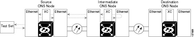
Performing the facility loopback test on an intermediate port isolates whether this node is causing circuit failure. It is shown in Figure 1-12.

Figure 1-12 Facility (Line) Loopback on an Intermediate-Node Ethernet Port


Caution Performing a loopback on an in-service circuit is service-affecting.


Note Facility loopbacks require on-site personnel.


Complete the "Create a Facility (Line) Loopback on an Intermediate-Node Ethernet Port" procedure.

Create a Facility (Line) Loopback on an Intermediate-Node Ethernet Port


Step 1 Connect an optical test set to the ASAP card Ethernet port you are testing: If you are starting the current procedure without the optical test set hooked up to the source ASAP card Ethernet port, use appropriate cabling to attach the Tx and Rx terminals of the optical test set to the port you are testing. Both Tx and Rx connect to the same port.


Note For specific procedures to use the test set equipment, consult the manufacturer.


Step 2 Adjust the test set accordingly. (Refer to manufacturer instructions for test-set use.)

Step 3 Use CTC to set up the facility loopback on the test port:

a. In node view, click the Circuits tab and click Create.

b. In the Circuit Creation dialog box, choose the type, such as STS, and number, such as 1.

c. Click Next.

d. In the next Circuit Creation dialog box, give the circuit an easily identifiable name such as Eth1toEth3.

e. Leave the Bidirectional check box checked.

f. Click Next.

g. In the Circuit Creation source dialog box, select the same Node, card Slot, Port, and STS (or VT) where the test set is connected.

h. Click Next.

i. In the Circuit Creation destination dialog box, use the same Node, card Slot, Port, and STS (or VT) used for the source dialog box.

j. Click Next.

k. In the Circuit Creation circuit routing preferences dialog box, leave all defaults. Click Finish.

Step 4 Confirm that the newly created circuit appears on the Circuits tab list as a two-way circuit.


Note It is normal for the "LPBKFACILITY (GIGE)" condition on page 2-87 to appear during a loopback setup. The condition clears when you remove the loopback.


Step 5 Create the facility loopback on the destination port being tested:

a. Go to the node view of the intermediate node:

Choose View > Go To Other Node from the menu bar.

Choose the node from the drop-down list in the Select Node dialog box and click OK.

b. In node view, double-click the intermediate-node card that requires the loopback.

c. Click the or Maintenance > Ethernet > Loopback > Port tabs.

d. Select OOS,MT from the Admin State column. If multiple ports are available, select the row appropriate for the desired port.

e. Select Facility (Line) from the Loopback Type column. If multiple ports are available, select the row appropriate for the desired port.

f. Click Apply.

g. Click Yes in the confirmation dialog box.

Step 6 Complete the "Test and Clear the Ethernet Facility (Line) Loopback Circuit" procedure.


Test and Clear the Ethernet Facility (Line) Loopback Circuit


Step 1 If the test set is not already sending traffic, send test traffic on the loopback circuit.

Step 2 Examine the traffic received by the test set. Look for errors or any other signal information that the test set is capable of indicating.

Step 3 If the test set indicates a good circuit, no further testing is necessary with the facility loopback. Clear the facility loopback from the port:

a. Click the Maintenance > Ethernet > Loopback > Port tabs.

b. Choose None from the Loopback Type column for the port being tested.

c. Choose the appropriate state (IS; OOS,DSBLD; OOS,MT) from the Admin State column for the port being tested.

d. Click Apply.

e. Click Yes in the confirmation dialog box.

Step 4 Clear the loopback circuit:

a. Click the Circuits tab.

b. Choose the loopback circuit being tested.

c. Click Delete.

d. Click Yes in the Delete Circuits dialog box. Do not check any check boxes.

Step 5 Complete the "Test the ASAP Card" procedure.


Test the ASAP Card


Step 1 Determine whether you are experiencing trouble on a single SFP (PPM), on all PPMs within a 4PIO (PIM), or on all 4PIO used in that ASAP card. If there is only partial failure, you may be able to replace this part rather than the entire card.

Step 2 If the errors are being observed on one port but not all ports of the ASAP, you may only need to replace that SFP (PPM). Remove the errored SFP (PPM) and replace it with a known-good SFP (PPM) by completing the procedures for this in the "Install Cards and Fiber-Optic Cable" chapter of the Cisco ONS 15600 Procedure Guide.

Step 3 If all SFPs (PPMs) on a particular 4PIO (PIM) are experiencing problems, the 4PIO (PIM) is indicated. Remove this 4PIO (PIM) and replace it with a known-good one using the procedures for this in the "Install Cards and Fiber-Optic Cable" chapter of the Cisco ONS 15600 Procedure Guide.

Step 4 If the trouble still is not located, complete the "Replace an OC-48 Card or OC-192 Card" procedure on page 2-138 for the suspected bad ASAP card and replace it with a known-good one.


Caution Removing a card that currently carries traffic on one or more ports can cause a traffic hit. To avoid this, perform an external switch if a switch has not already occurred. See the procedures in the "2.8.2  Protection Switching, Lock Initiation, and Clearing" section on page 2-126. For more information, refer to the "Maintain the Node" chapter of the Cisco ONS 15600 Procedure Guide.

Step 5 Resend test traffic on the loopback circuit with a known-good ASAP card installed.

Step 6 If the test set indicates a good circuit, the problem was probably the defective card. Return the defective card to Cisco through the RMA process. Contact Cisco Technical Support (1 800 553-2447).

Step 7 Complete the "Replace an OC-48 Card or OC-192 Card" procedure on page 2-138 for the faulty card.

Step 8 Clear the facility loopback from the port:

a. Click the Maintenance > Ethernet > Loopback > Port tabs.

b. Choose None from the Loopback Type column for the ASAP port being tested.

c. Choose the appropriate state (IS; OOS,DSBLD; OOS,MT) from the Admin State column for the port being tested.

d. Click Apply.

e. Click Yes in the confirmation dialog box.

Step 9 Clear the loopback circuit:

a. Click the Circuits tab.

b. Choose the loopback circuit being tested.

c. Click Delete.

d. Click Yes in the Delete Circuits dialog box. Do not check any check boxes.

Step 10 Complete the "Create a Terminal (Inward) Loopback on an Intermediate-Node Ethernet Port" procedure.


1.3.4  Create a Terminal (Inward) Loopback on an Intermediate-Node Ethernet Port

In the next troubleshooting test, you perform a terminal loopback on the intermediate-node ASAP Ethernet port to isolate whether the destination port is causing circuit trouble. In the example situation in Figure 1-13, the terminal loopback is performed on an intermediate Ethernet port in the circuit. You first create a bidirectional circuit that originates on the source-node Ethernet port and loops back on the intermediate-node port. You then proceed with the terminal loopback test. If you successfully complete a terminal loopback on the node, this node is excluded from possible sources of circuit trouble.

Figure 1-13 Terminal Loopback on an Intermediate-Node Ethernet Port


Caution Performing a loopback on an in-service circuit is service-affecting.


Note Terminal loopbacks require on-site personnel.


Complete the "Create a Terminal Loopback on an Intermediate-Node Ethernet Port" procedure.

Create a Terminal Loopback on an Intermediate-Node Ethernet Port


Step 1 Connect an optical test set to the intermediate node ASAP card Ethernet port you are testing:


Note For specific procedures to use the test set equipment, consult the manufacturer.


a. If you just completed the "Create a Facility (Line) Loopback on an Intermediate-Node Ethernet Port" procedure for an ASAP card Ethernet port, leave the optical test set hooked up to the intermediate-node port.

b. If you are starting the current procedure without the optical test set hooked up to the source port, use appropriate cabling to attach the Tx and Rx terminals of the optical test set to the port you are testing. Both Tx and Rx connect to the same port.

Step 2 Adjust the test set accordingly. (Refer to manufacturer instructions for test-set use.)

Step 3 Use CTC to set up the terminal loopback on the test port:

a. In node view, click the Circuits tab and click Create.

b. In the Circuit Creation dialog box, choose the type, such as STS, and number, such as 1.

c. Click Next.

d. In the next Circuit Creation dialog box, give the circuit an easily identifiable name such as Eth1toEth4.

e. Leave the Bidirectional check box checked.

f. Click Next.

g. In the Circuit Creation source dialog box, select the same Node, card Slot, Port, and STS (or VT) where the test set is connected.

h. Click Next.

i. In the Circuit Creation destination dialog box, use the same Node, card Slot, Port, and STS (or VT) used for the source dialog box.

j. Click Next.

k. In the Circuit Creation circuit routing preferences dialog box, leave all defaults. Click Finish.

Step 4 Confirm that the newly created circuit appears on the Circuits tab list and that it is described in the Dir column as a two-way circuit.


Note It is normal for the "LPBKTERMINAL (GIGE)" condition on page 2-89 to appear during a loopback setup. The condition clears when you remove the loopback.


Step 5 Create the terminal loopback on the intermediate port being tested:

a. Go to the node view of the intermediate node:

Choose View > Go To Other Node from the menu bar.

Choose the node from the drop-down list in the Select Node dialog box and click OK.

b. In node view, double-click the card that requires the loopback.

c. Click the Maintenance > Ethernet > Loopback > Port tabs.

d. Select OOS,MT from the Admin State column. If multiple ports are available, select the row appropriate for the desired port.

e. Select Terminal (Inward) from the Loopback Type column. If multiple ports are available, select the row appropriate for the desired port.

f. Click Apply.

g. Click Yes in the confirmation dialog box.

Step 6 Complete the "Test and Clear the Ethernet Terminal Loopback Circuit" procedure.


Test and Clear the Ethernet Terminal Loopback Circuit


Step 1 If the test set is not already sending traffic, send test traffic on the loopback circuit.

Step 2 Examine the test traffic being received by the test set. Look for errors or any other signal information that the test set is capable of indicating.

Step 3 If the test set indicates a good circuit, no further testing is necessary on the loopback circuit. Clear the terminal loopback from the port:

a. Double-click the intermediate-node card with the terminal loopback to display the card view.

b. Click the Maintenance > Ethernet > Loopback > Port tabs.

c. Select None from the Loopback Type column for the port being tested.

d. Select the appropriate state (IS; OOS,DSBLD; OOS,MT) in the Admin State column for the port being tested.

e. Click Apply.

f. Click Yes in the confirmation dialog box.

Step 4 Clear the terminal loopback circuit:

a. Click the Circuits tab.

b. Choose the loopback circuit being tested.

c. Click Delete.

d. Click Yes in the Delete Circuits dialog box. Do not check any check boxes.

Step 5 Complete the "Test the ASAP Card" procedure.


Test the ASAP Card


Step 1 Determine whether you are experiencing trouble on a single SFP (PPM), on all PPMs within a 4PIO (PIM), or on all 4PIO used in that ASAP card. If there is only partial failure, you may be able to replace this part rather than the entire card.

Step 2 If the errors are being observed on one port but not all ports of the ASAP, you may only need to replace that SFP (PPM). Remove the errored SFP (PPM) and replace it with a known-good SFP (PPM) by completing the procedures for this in the "Install Cards and Fiber-Optic Cable" chapter of the Cisco ONS 15600 Procedure Guide.

Step 3 If all SFPs (PPMs) on a particular 4PIO (PIM) are experiencing problems, the 4PIO (PIM) is indicated. Remove this 4PIO (PIM) and replace it with a known-good one using the procedures for this in the "Install Cards and Fiber-Optic Cable" chapter of the Cisco ONS 15600 Procedure Guide.

Step 4 If the trouble still is not located, complete the "Replace an OC-48 Card or OC-192 Card" procedure on page 2-138 for the suspected bad ASAP card and replace it with a known-good one.


Caution Removing a card that currently carries traffic on one or more ports can cause a traffic hit. To avoid this, perform an external switch if a switch has not already occurred. See the procedures in the "2.8.2  Protection Switching, Lock Initiation, and Clearing" section on page 2-126. For more information, refer to the "Maintain the Node" chapter of the Cisco ONS 15600 Procedure Guide.

Step 5 Resend test traffic on the loopback circuit with a known-good card.

Step 6 If the test set indicates a good circuit, the problem was probably the defective card. Return the defective card to Cisco through the RMA process. Contact Cisco Technical Support (1 800 553-2447).

Step 7 Complete the "Replace an OC-48 Card or OC-192 Card" procedure on page 2-138 for the defective card.

Step 8 Clear the terminal loopback on the port:

a. Double-click the intermediate-node ASAP card with the terminal loopback.

b. Click the Maintenance > Ethernet > Loopback > Port tab.

c. Select None from the Loopback Type column for the port being tested.

d. Select the appropriate state (IS; OOS,DSBLD; OOS,MT) in the Admin State column for the port being tested.

e. Click Apply.

f. Click Yes in the confirmation dialog box.

Step 9 Clear the terminal loopback circuit:

a. Click the Circuits tab.

b. Choose the loopback circuit being tested.

c. Click Delete.

d. Click Yes in the Delete Circuits dialog box. Do not check any check boxes.

Step 10 Complete the "Perform a Facility (Line) Loopback on a Destination-Node Ethernet Port" procedure.


1.3.5  Perform a Facility (Line) Loopback on a Destination-Node Ethernet Port

You perform a facility loopback test for ASAP card Ethernet port at the destination port to determine whether this local port is the source of circuit trouble. The example in Figure 1-14 shows a facility loopback being performed on an Ethernet port.

Figure 1-14 Facility (Line) Loopback on a Destination-Node Ethernet Port


Caution Performing a loopback on an in-service circuit is service-affecting.


Note Facility loopbacks require on-site personnel.


Complete the "Create the Facility (Line) Loopback on a Destination-Node Ethernet Port" procedure.

Create the Facility (Line) Loopback on a Destination-Node Ethernet Port


Step 1 Connect an optical test set to the destination ASAP card optical port you are testing. If you are starting the current procedure without the optical test set hooked up to the source optical port, use appropriate cabling to attach the Tx and Rx terminals of the optical test set to the port you are testing. Both Tx and Rx connect to the same port.


Note For specific procedures to use the test set equipment, consult the manufacturer.


Step 2 Adjust the test set accordingly. (Refer to manufacturer instructions for test-set use.)

Step 3 Use CTC to set up the hairpin circuit on the test port:

a. In node view, click the Circuits tab and click Create.

b. In the Circuit Creation dialog box, choose the type, such as STS, and number, such as 1.

c. Click Next.

d. In the next Circuit Creation dialog box, give the circuit an easily identifiable name such as Eth1toEth5.

e. Leave the Bidirectional check box checked.

f. Click Next.

g. In the Circuit Creation source dialog box, select the same Node, card Slot, Port, and STS (or VT) where the test set is connected.

h. Click Next.

i. In the Circuit Creation destination dialog box, use the same Node, card Slot, Port, and STS (or VT) used for the source dialog box.

j. Click Next.

k. In the Circuit Creation circuit routing preferences dialog box, leave all defaults. Click Finish.

Step 4 Confirm that the newly created circuit appears on the Circuits tab list as a two-way circuit.


Note It is normal for the "LPBKFACILITY (GIGE)" condition on page 2-87 to appear during a loopback setup. The condition clears when you remove the loopback.


Step 5 Create the facility loopback on the destination port being tested:

a. Go to the node view of the destination node:

Choose View > Go To Other Node from the menu bar.

Choose the node from the drop-down list in the Select Node dialog box and click OK.

b. In node view, double-click the card that requires the loopback.

c. Click the Maintenance > Ethernet > Loopback > Port tabs.

d. Select OOS,MT from the Admin State column. If multiple ports are available, select the row appropriate for the desired port.

e. Select Facility (Line) from the Loopback Type column. If multiple ports are available, select the row appropriate for the desired port.

f. Click Apply.

g. Click Yes in the confirmation dialog box.

Step 6 Complete the "Test and Clear the Ethernet Facility (Line) Loopback Circuit" procedure.


Test and Clear the Ethernet Facility (Line) Loopback Circuit


Step 1 If the test set is not already sending traffic, send test traffic on the loopback circuit.

Step 2 Examine the traffic received by the test set. Look for errors or any other signal information that the test set is capable of indicating.

Step 3 If the test set indicates a good circuit, no further testing is necessary with the facility loopback. Clear the facility loopback from the port:

a. Click the Maintenance > Ethernet > Loopback > Port tabs.

b. Choose None from the Loopback Type column for the port being tested.

c. Choose the appropriate state (IS; OOS,DSBLD; OOS,MT) from the Admin State column for the port being tested.

d. Click Apply.

e. Click Yes in the confirmation dialog box.

Step 4 Clear the loopback circuit:

a. Click the Circuits tab.

b. Choose the loopback circuit being tested.

c. Click Delete.

d. Click Yes in the Delete Circuits dialog box. Do not check any check boxes.

Step 5 Complete the "Test the ASAP Card" procedure.


Test the ASAP Card


Step 1 Determine whether you are experiencing trouble on a single SFP (PPM), on all PPMs within a 4PIO (PIM), or on all 4PIO used in that ASAP card. If there is only partial failure, you may be able to replace this part rather than the entire card.

Step 2 If the errors are being observed on one port but not all ports of the ASAP, you may only need to replace that SFP (PPM). Remove the errored SFP (PPM) and replace it with a known-good SFP (PPM) by completing the procedures for this in the "Install Cards and Fiber-Optic Cable" chapter of the Cisco ONS 15600 Procedure Guide.

Step 3 If all SFPs (PPMs) on a particular 4PIO (PIM) are experiencing problems, the 4PIO (PIM) is indicated. Remove this 4PIO (PIM) and replace it with a known-good one using the procedures for this in the "Install Cards and Fiber-Optic Cable" chapter of the Cisco ONS 15600 Procedure Guide.

Step 4 If the trouble still is not located, complete the "Replace an OC-48 Card or OC-192 Card" procedure on page 2-138 for the suspected bad ASAP card and replace it with a known-good one.


Caution Removing a card that currently carries traffic on one or more ports can cause a traffic hit. To avoid this, perform an external switch if a switch has not already occurred. See the procedures in the "2.8.2  Protection Switching, Lock Initiation, and Clearing" section on page 2-126. For more information, refer to the "Maintain the Node" chapter of the Cisco ONS 15600 Procedure Guide.

Step 5 Resend test traffic on the loopback circuit with a known-good card installed.

Step 6 If the test set indicates a good circuit, the problem was probably the defective card. Return the defective card to Cisco through the RMA process. Contact Cisco Technical Support (1 800 553-2447).

Step 7 Complete the "Replace an OC-48 Card or OC-192 Card" procedure on page 2-138 for the faulty card.

Step 8 Clear the facility loopback on the port:

a. Click the Maintenance > Ethernet > Loopback > Port tabs.

b. Choose None from the Loopback Type column for the port being tested.

c. Choose the appropriate state (IS; OOS,DSBLD; OOS,MT) from the Admin State column for the port being tested.

d. Click Apply.

e. Click Yes in the confirmation dialog box.

Step 9 Clear the loopback circuit:

a. Click the Circuits tab.

b. Choose the loopback circuit being tested.

c. Click Delete.

d. Click Yes in the Delete Circuits dialog box. Do not check any check boxes.

Step 10 Complete the "Perform a Terminal Loopback on a Destination-Node Ethernet Port" procedure.


1.3.6  Perform a Terminal Loopback on a Destination-Node Ethernet Port

The terminal loopback at the destination-node ASAP card Ethernet port is the final local hardware error elimination in the circuit troubleshooting process, and is performed on the destination-node ASAP card Ethernet port. If this test is completed successfully, you have verified that the circuit is good up to the destination port. The example in Figure 1-15 shows a terminal loopback on a destination-node Ethernet port.

Figure 1-15 Terminal Loopback on a Destination-Node Ethernet Port


Caution Performing a loopback on an in-service circuit is service-affecting.


Note Terminal loopbacks require on-site personnel.


Complete the "Create the Terminal Loopback on a Destination-Node Ethernet Port" procedure.

Create the Terminal Loopback on a Destination-Node Ethernet Port


Step 1 Connect an optical test set to the destination node ASAP card Ethernet port you are testing:


Note For specific procedures to use the test set equipment, consult the manufacturer.


a. If you just completed the "Perform a Facility (Line) Loopback on a Destination-Node Ethernet Port" procedure for an ASAP card Ethernet port, leave the optical test set hooked up to the source port.

b. If you are starting the current procedure without the optical test set hooked up to the source port, use appropriate cabling to attach the Tx and Rx terminals of the optical test set to the port you are testing. Both Tx and Rx connect to the same port.

Step 2 Adjust the test set accordingly. (Refer to manufacturer instructions for test-set use.)

Step 3 Use CTC to set up the terminal loopback on the test port:

a. In node view, click the Circuits tab and click Create.

b. In the Circuit Creation dialog box, choose the type, such as STS, and number, such as 1.

c. Click Next.

d. In the next Circuit Creation dialog box, give the circuit an easily identifiable name such as Eth1toEth6.

e. Leave the Bidirectional check box checked.

f. Click Next.

g. In the Circuit Creation source dialog box, select the same Node, card Slot, Port, and STS (or VT) where the test set is connected.

h. Click Next.

i. In the Circuit Creation destination dialog box, use the same Node, card Slot, Port, and STS (or VT) used for the source dialog box.

j. Click Next.

k. In the Circuit Creation circuit routing preferences dialog box, leave all defaults. Click Finish.

Step 4 Confirm that the newly created circuit appears on the Circuits tab list as a two-way circuit.


Note It is normal for the "LPBKTERMINAL (GIGE)" condition on page 2-89 to appear during a loopback setup. The condition clears when you remove the loopback.


Step 5 Create the terminal loopback on the destination port being tested:

a. Go to the node view of the destination node:

Choose View > Go To Other Node from the menu bar.

Choose the node from the drop-down list in the Select Node dialog box and click OK.

b. In node view, double-click the card that requires the loopback.

c. Click the Maintenance > Ethernet > Loopback > Port tab.

d. Select OOS,MT from the Admin State column. If multiple ports are available, select the row appropriate for the desired port.

e. Select Terminal (Inward) from the Loopback Type column. If multiple ports are available, select the row appropriate for the desired port.

f. Click Apply.

g. Click Yes in the confirmation dialog box.

Step 6 Complete the "Test and Clear the Ethernet Terminal Loopback Circuit" procedure.


Test and Clear the Ethernet Terminal Loopback Circuit


Step 1 If the test set is not already sending traffic, send test traffic on the loopback circuit.

Step 2 Examine the test traffic being received by the test set. Look for errors or any other signal information that the test set is capable of indicating.

Step 3 If the test set indicates a good circuit, no further testing is necessary on the loopback circuit. Clear the terminal loopback from the port:

a. Double-click the destination-node ASAP card.

b. Click the Maintenance > Ethernet > Loopback > Port tab.

c. Select None from the Loopback Type column for the port being tested.

d. Select the appropriate state (IS; OOS,DSBLD; OOS,MT) in the Admin State column for the port being tested.

e. Click Apply.

f. Click Yes in the confirmation dialog box.

Step 4 Clear the terminal loopback circuit:

a. Click the Circuits tab.

b. Choose the loopback circuit being tested.

c. Click Delete.

d. Click Yes in the Delete Circuits dialog box. Do not check any check boxes.

The entire circuit path has now passed its comprehensive series of loopback tests. This circuit qualifies to carry live traffic.

Step 5 If the test set indicates a faulty circuit, the problem might be a faulty card.

Step 6 Complete the "Test the ASAP Card" procedure.


Test the ASAP Card


Step 1 Determine whether you are experiencing trouble on a single SFP (PPM), on all PPMs within a 4PIO (PIM), or on all 4PIO used in that ASAP card. If there is only partial failure, you may be able to replace this part rather than the entire card.

Step 2 If the errors are being observed on one port but not all ports of the ASAP, you may only need to replace that SFP (PPM). Remove the errored SFP (PPM) and replace it with a known-good SFP (PPM) by completing the procedures for this in the "Install Cards and Fiber-Optic Cable" chapter of the Cisco ONS 15600 Procedure Guide.

Step 3 If all SFPs (PPMs) on a particular 4PIO (PIM) are experiencing problems, the 4PIO (PIM) is indicated. Remove this 4PIO (PIM) and replace it with a known-good one using the procedures for this in the "Install Cards and Fiber-Optic Cable" chapter of the Cisco ONS 15600 Procedure Guide.

Step 4 If the trouble still is not located, complete the "Replace an OC-48 Card or OC-192 Card" procedure on page 2-138 for the suspected bad ASAP card and replace it with a known-good one.


Caution Removing a card that currently carries traffic on one or more ports can cause a traffic hit. To avoid this, perform an external switch if a switch has not already occurred. See the procedures in the "2.8.2  Protection Switching, Lock Initiation, and Clearing" section on page 2-126. For more information, refer to the "Maintain the Node" chapter of the Cisco ONS 15600 Procedure Guide.

Step 5 Resend test traffic on the loopback circuit with a known-good card.

Step 6 If the test set indicates a good circuit, the problem was probably the defective card. Return the defective card to Cisco through the RMA process. Contact Cisco Technical Support (1 800 553-2447).

Step 7 Complete the "Replace an OC-48 Card or OC-192 Card" procedure on page 2-138 for the defective card.

Step 8 Clear the terminal loopback on the port:

a. Double-click the destination-node ASAP card.

b. Click the Maintenance > Ethernet > Loopback > Port tab.

c. Select None from the Loopback Type column for the port being tested.

d. Select the appropriate state (IS; OOS,DSBLD; OOS,MT) in the Admin State column for the port being tested.

e. Click Apply.

f. Click Yes in the confirmation dialog box.

Step 9 Clear the terminal loopback circuit:

a. Click the Circuits tab.

b. Choose the loopback circuit being tested.

c. Click Delete.

d. Click Yes in the Delete Circuits dialog box. Do not check any check boxes.

The entire circuit path has now passed its comprehensive series of loopback tests. This circuit qualifies to carry live traffic.


1.4  Using CTC Diagnostics

CTC provides diagnostics for the following functions:

Verification of proper card ASICS function

Verification of standby card operation

Verification of proper card LED operation

Notification of problems detected via alarms

Provision of a downloaded, machine-readable diagnostic log file to be used by Cisco Technical Support

Some of these functions, such as ASIC verification and standby card operation, are invisibly monitored in background functions. Change or problem notifications are provided in the Alarms and Conditions window. Other diagnostic functions—verifying card LED function or downloading diagnostic files for technical support—are available to the user in the node view Maintenance > Diagnostic tab. The user-operated diagnostic features are described in the following paragraphs.

1.4.1  Card LED Lamp Tests

A card LED lamp test determines whether card-level indication LEDs are operational. This diagnostic test is run as part of the initial ONS 15600 turnup, during maintenance routines, or any time you question whether an LED is in working order. Maintenance or higher-level users can complete the following tasks to verify LED operation.

1.4.1.1  Verify Card LED Operation


Note The LED test must be performed on the physical card. This test is not available in the CTC interface. For typical OC-N, SSXC, and TSC card LED behavior, see the "2.7  LED Behavior" section on page 2-123.


Step 1 Determine the active TSC card using the green ACT /STBY LED on the face of the card.

Step 2 Press the LAMP button on the face of the active TSC card.

Step 3 Ensure that all the LEDs on the cards in the shelf illuminate for several seconds.

Step 4 If an LED does not illuminate, the LED might be faulty.

Return the defective card to Cisco through the returned materials authorization (RMA) process. Contact Cisco Technical Support (1 800 553-2447).


1.4.2  Retrieve Diagnostics File Button

When you click the Retrieve Diagnostics File button in the Maintenance window, CTC retrieves system data that can be off-loaded by a Maintenance or higher-level user to a local directory and sent to Technical Support for troubleshooting purposes. The diagnostics file is in machine language and is not human-readable, but can be used by TAC for problem analysis. Complete the following task to off-load the diagnostics file.


Note In addition to the machine-readable diagnostics file, the ONS 15600 also stores an audit trail of all system events such as user logins, remote logins, configuration, and changes. This audit trail is considered a record-keeping feature rather than a troubleshooting feature. Information about the feature is located in the Cisco ONS 15600 Procedure Guide.


Off-Load the Diagnostics File


Step 1 In the node view, click the Maintenance > Diagnostic tab.

Step 2 Click Retrieve Diagnostic File.

Step 3 In the Saving Diagnostic File dialog box, navigate to the directory (local or network) where you want to save the file.

Step 4 Enter a name in the File Name field.

You do not have to give the archive file a particular extension. It is readable in any application that supports text files, such as WordPad, Microsoft Word (imported), etc.

Step 5 Click Save.

The Get Diagnostics status window shows a progress bar indicating the percentage of the file being saved, then shows "Get Diagnostics Complete."

Step 6 Click OK.


1.5  Restoring the Database to a Previous or Original Configuration

This section contains troubleshooting for node operation errors that might require restoring software data or restoring the node to the default setup.

1.5.1  Node is Functioning Improperly or Has Incorrect Data

Symptom    One or more nodes are not functioning properly or have incorrect data.

Table 1-1 describes the potential cause of the symptom and the solution.

Table 1-1 Node is Functioning Improperly or Has Incorrect Data 

Possible Problem
Solution

The node has an incorrect or corrupted database.

Complete the procedures in the "Maintain the Node" chapter of the Cisco ONS 15600 Procedure Guide.


1.6  PC Connectivity Troubleshooting

This section contains information about system minimum requirements, supported platforms, browsers, and JREs for R6.0, and troubleshooting procedures for PC and network connectivity to the ONS 15600.

1.6.1  PC System Minimum Requirements

Workstations running CTC R6.0 for the ONS products on Windows platforms need to have the following minimum requirements:

Pentium III or higher processor

Processor speed of at least 700 MHz

256 Mb or more of RAM

50 Mb or more of available hard disk space

20 GB or larger hard drive

1.6.2  Sun System Minimum Requirements

Workstations running CTC R6.0 for the ONS products on Sun workstations need to have the following minimum requirements:

UltraSPARC or faster processor

256 Mb or more of RAM

50 Mb or more of available hard disk space

1.6.3  Supported Platforms, Browsers, and JREs

Software R6.0 CTC supports the following platforms:

Windows NT

Windows 98

Windows XP

Windows 2000

Solaris 8

Solaris 9

Software R6.0 CTC supports the following browsers and JREs:

Netscape 7 browser (on Solaris 8 or 9 with Java plug-in 1.4.2)

PC platforms with Java plug-in 1.4.2

Internet Explorer 6.0 browser (on PC platforms with Java plug-in 1.4.2)

Mozilla application suite for browsers


Note You can obtain browsers at the following URLs:
Internet Explorer: http://www.microsoft.com
Mozilla: http://mozilla.org


Note The required JRE version is JRE 1.4.2.


Note JRE 1.4.2 for Windows and Solaris is available on R6.0 product CDs.


1.6.4  Unsupported Platforms and Browsers

Software R6.0 does not support the following platforms:

Windows 95

Solaris 2.5

Solaris 2.6

Software R6.0 does not support the following browsers and JREs:

Netscape 4.73 for Windows.

Netscape 4.76 on Solaris is not supported.

Netscape 7 on Solaris 8 or 9 is only supported with JRE 1.4.2

1.6.5  Retrieve the Node Information

If you do not know the IP address of your ONS 15600 network element (NE), you can obtain and view the NE information using a TL1 session.


Step 1 Connect a 3-pair swapping null modem adapter to the RS-232 port on the customer access panel (CAP).

Step 2 Connect a serial cable to the null modem adapter and to the serial port on your PC.

Step 3 Configure the terminal emulation software (HyperTerminal):

a. Terminal emulation = vt100

b. Bits per second = 9600

c. Parity = None

d. Stop BITS = 1

e. Flow control = None

Step 4 Press Enter. A > prompt appears.

Step 5 At the prompt, type the Activate User command to open a TL1 session:

ACT-USER::CISCO15:<CTAG>::<PID>;


Note When the semicolon is typed, the TL1 command is executed immediately.


Step 6 At the prompt, type the Retrieve Network Element General command to retrieve the NE information:

RTRV-NE-GEN:::<CTAG>;

Step 7 The response message will provide the following NE information.

<IPADDR> indicates the node IP address; <IPADDR> is a string

<IPMASK> indicates the node IP mask; <IPMASK> is a string

<DEFRTR> indicates the node default router; <DEFRTR> is a string

<NAME> is the node name. The maximum name size is 20 characters; <name> is a string

<SWVER> is the software version; <SWVER> is a string

<LOAD> is the load version; <LOAD> is a string

<SELCLK> is the system-wide selected clock/sync copy; <SELCLK> is of type DATA_CLK_COPY

<PREFCLK> is the preferred clock/sync copy; <PREFCLK> is of type DATA_CLK_COPY

<SELDATA> is the system-wide selected data copy; <SELDATA> is of type DATA_CLK_COPY

<PREFDATA> is the preferred data copy; <SELDATA> is of type DATA_CLK_COPY

Step 8 At the prompt, type the Cancel User command to close the TL1 session:

CANC-USER::CISCO15:<CTAG>;

Step 9 Remove the serial cable from the null modem adapter on the CAP and the serial port on your PC.

Step 10 Remove the null modem adapter from the RS-232 port on the CAP.


1.6.6  Unable to Ping Your PC

Symptom    When connecting your PC to the ONS 15600, you are unable to ping the IP address of your PC to verify the IP configuration.

Table 1-2 describes the potential causes of the symptom and the solutions.

Table 1-2 Unable to Ping Your PC 

Possible Problem
Solution

The IP address was typed incorrectly.

Verify that the IP address used to ping the PC matches the IP address displayed in the Windows IP Configuration information retrieved from the system. See the "Verify the IP Configuration of Your PC" procedure.

The IP configuration of your PC is not properly set.

To verify the IP configuration of your PC, see the "Verify the IP Configuration of Your PC" procedure. If this procedure is unsuccessful, contact your network administrator for instructions to correct the IP configuration of your PC.


1.6.6.1  Verify the IP Configuration of Your PC


Step 1 Open a DOS command window by selecting Start > Run from the Start menu on your PC.

Step 2 In the Run window open field, type command and then click OK. The DOS command window appears.

Step 3 At the prompt in the DOS window, type one of the following commands:

For Windows 98, NT, 2000, and XP, type ipconfig and press the Enter key.

The Windows IP configuration information appears, including the IP address, Subnet Mask, and the Default Gateway.

Step 4 At the prompt in the DOS window, type ping followed by the IP address you verified in Step 3.

Step 5 Press the Enter key to execute the command.

If the DOS window displays multiple (usually four) replies, the IP configuration is working properly.

If you do not receive a reply, your IP configuration might not be properly set. Contact your network administrator for instructions to correct the IP configuration of your PC.


1.6.7  Browser Login Does Not Launch Java

Symptom    The message "Loading Java Applet" does not appear and the JRE does not launch during the initial login.

Table 1-3 describes the potential cause of the symptom and the solutions.

Table 1-3 Browser Login Does Not Launch Java 

Possible Problem
Solution

The PC operating system and browser are not properly configured.

Reconfigure the PC operating system and the browser.

See the "Reconfigure the PC Operating System and the Browser" procedure.


1.6.7.1  Reconfigure the PC Operating System and the Browser


Step 1 From the Windows start menu, click Settings > Control Panel.

Step 2 If Java Plug-in Control Panel does not appear, the JRE might not be installed on your PC.

a. Run the Cisco ONS 15600 software CD.

b. Open the [CD drive]:\Windows\JRE folder.

c. Double-click the jre-1_4_2-win icon to run the JRE installation wizard.

d. Follow the JRE installation wizard steps.

Step 3 From the Windows start menu, click Settings > Control Panel.

Step 4 Double-click the Java Plug-in 1.4.2 icon.

Step 5 Click Advanced on the Java Plug-in Control Panel.

Step 6 From the Java Run Time Environment menu, choose JRE 1.4 in C:\ProgramFiles\JavaSoft\JRE\1.4.2.

Step 7 Click Apply.

Step 8 In Communicator, click Edit > Preferences.

Step 9 Click Advanced > Proxies > Direct connection to the Internet > OK.

Step 10 Again on Communicator, click Edit > Preferences.

Step 11 Click Advanced > Cache.

Step 12 Confirm that the Disk Cache Folder field shows the following:

Problem   C:\ProgramFiles\Netscape\<username>\Communicator\cache for platform/platform.

Step 13 If the Disk Cache Folder field is not correct, click Choose Folder.

Step 14 Navigate to the file listed in Step 12 and click OK.

Step 15 Click OK in the Preferences window and exit the browser.

Step 16 Temporarily disable any virus-scanning software on the computer. See the "Browser Stalls When Downloading JAR Files From TSC Card" procedure.

Step 17 Verify that the computer does not have two network interface cards (NICs) installed. If the computer does have two NICs, remove one.

Step 18 Restart the browser and log into the ONS 15600.


1.6.8  Unable to Verify the NIC Connection on your PC

Symptom    When connecting your PC to the ONS 15600, you are unable to verify that the NIC connection is working properly because the link LED is not illuminated or flashing.

Table 1-4 describes the potential causes of the symptom and the solutions.

Table 1-4 Unable to Verify the NIC Connection on Your PC 

Possible Problem
Solution

The CAT-5 cable is not plugged in properly.

Confirm that both ends of the cable are properly inserted. If the cable is not fully inserted because of a broken locking clip, replace the cable.

The CAT-5 cable is damaged.

Ensure that the cable is in good condition. If in doubt, use a known-good cable. Often, cabling is damaged due to pulling or bending.

Incorrect type of CAT-5 cable is being used.

CAP connection: To connect an ONS 15600 directly to your laptop/PC or a router, use a cross-over CAT-5 cable. To connect the ONS 15600 to a hub or a LAN switch, use a straight-through CAT-5 cable.

TSC card connection: To connect an ONS 15600 active TSC card directly to your laptop/PC, you might use either a straight-through or cross-over CAT-5 cable because the RJ-45 port on the faceplate is auto sensing.

For details on the types of CAT-5 cables, see the "Crimp Replacement CAT-5 Cables" procedure.

The NIC is improperly inserted or installed.

If you are using a PCMCIA based NIC, remove and reinsert the NIC to make sure the NIC is fully inserted.

If the NIC is built into the laptop/PC, verify that the NIC is not faulty.

The NIC is faulty.

Confirm that the NIC is working properly. If you have no issues connecting to the network (or any other node), the NIC should be working correctly.

If you have difficulty connecting to the network (or any other node), the NIC might be faulty and needs to be replaced.


1.6.9  TCP/IP Connection is Lost

Symptom    The TCP/IP connection was established and then lost, and a DISCONNECTED alarm appears on CTC.

Table 1-5 describes the potential cause of the symptom and the solution.

Table 1-5 TCP/IP Connection is Lost

Possible Problem
Solution

Your PC lost TCP/IP connection with the ONS 15600.

Use a standard ping command to verify the TCP/IP connection between the PC and the ONS 15600 TSC card. A ping command will work if the PC connects directly to the TSC card or uses a LAN to access the TSC card. A ping command will also work if the CTC is connected via a gateway network element (GNE) and DCC if the node and CTC are in the same subnet or the required static routes are configured.

See the "Ping the ONS 15600" procedure.


Ping the ONS 15600


Step 1 Display the command prompt:

a. If you are using a Microsoft Windows operating system, from the Start Menu choose Run, type command in the Open field of the Run dialog box, and click OK.

b. If you are using a Sun Solaris operating system, from the Common Desktop Environment (CDE) click the Personal Application tab and click Terminal.

Step 2 For both the Microsoft and Sun operating systems, type the following at the prompt:

ping [ONS 15600 IP address]

For example, ping 192.1.0.2.

If the workstation has connectivity to the ONS 15600, the ping is successful and displays a reply from the IP address. If the workstation does not have connectivity, a "Request timed out" message displays.

Step 3 If the ping is successful, it demonstrates that an active TCP/IP connection exists. Restart CTC.

Step 4 If the ping is not successful, and the workstation connects to the ONS 15600 through a LAN, verify that the workstation's IP address is on the same subnet as the ONS node.

If the ping is not successful and the workstation connects directly to the ONS 15600, verify that the link light on the workstation NIC is illuminated.


1.7  CTC Operation Troubleshooting

This section contains troubleshooting procedures for CTC login or operation problems.

1.7.1  Cisco Transport Controller Installation Wizard Hangs

Symptom    The CTC Installation Wizard hangs or stalls during Netscape Communicator installation when installing the RealPlayer G2 plug-in application from the Cisco ONS 15600 software or documentation CD-ROM.

Table 1-6 describes the potential cause of the symptom and the solutions.

Table 1-6 Cisco Transport Controller Installation Wizard Hangs

Possible Problem
Solution

RealPlayer G2 is incompatible with the CTC Installation Wizard when it is installed with the Netscape Communicator software from the CD.

Abort the installation. See the "Abort the Stalled Installation Wizard" procedure.

Restart the CTC Installation Wizard and perform a custom Netscape Communicator installation that excludes RealPlayer G2 from the items being installed. Refer to the Cisco ONS 15600 Procedure Guide to perform a custom installation that excludes RealPlayer G2.

Note The RealPlayer G2 software can be installed separately at a later time without affecting the other Cisco Transport Controller software.


Abort the Stalled Installation Wizard


Step 1 Abort the stalled CTC Installation Wizard by pressing Ctrl+Alt+Del. The Windows Security dialog appears.

Step 2 In the Windows Security dialog, click Task Manager.

Step 3 In the Windows Task Manager dialog, highlight the Cisco Transport Controller Installation Wizard and click the End Task button.

Step 4 Click Yes in the confirmation dialog box.

Step 5 Navigate to the drive containing the CTC CD-ROM and double-click setup.exe to restart the Cisco Transport Controller Installation Wizard.

Step 6 Refer to the Cisco ONS 15600 Procedure Guide to perform a custom Netscape Communicator installation that excludes RealPlayer G2 from the items to be installed.


1.7.2  Browser Stalls When Downloading JAR Files From TSC Card

Symptom    The browser stalls or hangs when downloading a Cisco Transport Controller JAR files from the TSC card.

Table 1-7 describes the potential cause of the symptom and the solution.

Table 1-7 Browser Stalls When Downloading JAR Files From TSC Card 

Possible Problem
Solution

McAfee VirusScan software might be interfering with the operation. The problem occurs when the VirusScan Download Scan is enabled on McAfee VirusScan 4.5 or later.

Run the CTC installation wizard to pre-install the CTC JAR files.

Disable the VirusScan Download Scan feature. See the "Disable the VirusScan Download Scanning" procedure.


1.7.2.1  Disable the VirusScan Download Scanning


Step 1 From the Windows start menu, choose Programs > Network Associates > VirusScan Console.

Step 2 Double-click the VShield icon listed in the VirusScan Console dialog box.

Step 3 Click the Configure button on the lower part of the Task Properties window.

Step 4 Click the Download Scan icon next to the System Scan Properties dialog box.

Step 5 Uncheck the Enable Internet download scanning checkbox.

Step 6 Click Yes when the warning message appears.

Step 7 Click OK in the System Scan Properties dialog box.

Step 8 Click OK in the Task Properties window.

Step 9 Close the McAfee VirusScan window.


1.7.3  Cisco Transport Controller Does Not Launch

Symptom    CTC does not launch and usually an error message appears before the login screen appears.

Table 1-8 describes the potential causes of the symptom and the solutions.

Table 1-8 Cisco Transport Controller Does Not Launch 

Possible Problem
Solution

The Communicator browser cache points to an invalid directory.

Redirect the Communicator cache to a valid directory. See the "Redirect the Communicator Cache to a Valid Directory" procedure.

The user is connected to the standby TSC card.

Connect the login PC to the port on the front of the active TSC card; the active TSC card has a green ACT/STBY LED illuminated.

Note For typical TSC card LED behavior, see the "2.7  LED Behavior" section on page 2-123.


1.7.3.1  Redirect the Communicator Cache to a Valid Directory


Step 1 Launch Netscape Communicator.

Step 2 Display the Edit menu.

Step 3 Choose Preferences.

Step 4 In the Category column on the left-hand side, go to Advanced and choose the Cache tab.

Step 5 Change your disk cache folder to point to the cache file location.

The cache file location is usually C:\ProgramFiles\Netscape\Users\<yourname>\cache. The <yourname> segment of the file location is often the same as the user name.


1.7.4  Sluggish Cisco Transport Controller Operation or Login Problems

Symptom    You experience sluggish CTC operation or have problems logging into CTC.

Table 1-9 describes the potential cause of the symptom and the solution.

Table 1-9 Sluggish Cisco Transport Controller Operation or Login Problems 

Possible Problem
Solution

The CTC cache file is corrupted.

Delete the CTC cache file. This operation forces the ONS 15600 to download a new set of .jar files to your computer hard drive. See the "Delete the CTC Cache File Automatically" procedure or the "Delete the CTC Cache File Manually" procedure.

Insufficient heap memory allocation.

Increase the heap size if you are using CTC to manage more than 50 nodes concurrently. See the "Set the CTC_HEAP and CTC_MAX_PERM_SIZE_HEAP Environment Variables for Windows" procedure and the "Set the CTC_HEAP and CTC_MAX_PERM_SIZE_HEAP Environment Variables for Solaris" procedure.

Note To avoid network performance issues, Cisco recommends managing a maximum of 50 nodes concurrently with CTC. To manage more than 50 nodes, Cisco recommends using Cisco Transport Manager (CTM). Cisco does not recommend running multiple CTC sessions when managing two or more large networks.


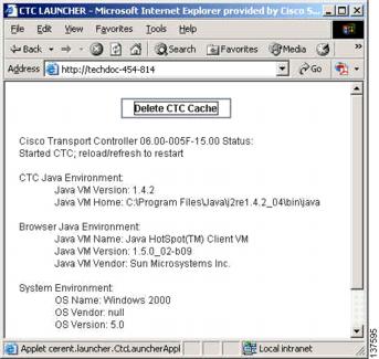
1.7.4.1  Delete the CTC Cache File Automatically


Step 1 Enter an ONS 15600 IP address into the browser URL field. The initial browser window shows a Delete CTC Cache button.

Step 2 Close all open CTC sessions and browser windows. The PC operating system will not allow you to delete files that are in use.

Step 3 Click the Delete CTC Cache button on the initial browser window to clear the CTC cache. Figure 1-16 shows the Delete CTC Cache window.

Figure 1-16 The Delete the CTC Cache Window


1.7.4.2  Delete the CTC Cache File Manually


Step 1 To delete the *.jar files manually, from the Windows Start menu choose Search > For Files or Folders.

Step 2 Enter ctc*.jar or cms*.jar in the Search for files or folders named field on the Search Results dialog box and click Search Now.

Step 3 Click the Modified column on the Search Results dialog box to find the *.jar files that match the date when you downloaded the files from the TSC card.

Step 4 Highlight the files and press the keyboard Delete key.

Step 5 Click Yes in the confirmation dialog box.


1.7.4.3  Set the CTC_HEAP and CTC_MAX_PERM_SIZE_HEAP Environment Variables for Windows


Note Before proceeding with the following steps, ensure that your system has a minimum of 1 GB of RAM. If your system does not have a minimum of 1 GB of RAM, contact the Cisco Technical Assistance Center (TAC).


Step 1 Close all open CTC sessions and browser windows.

Step 2 From the Windows Start menu, choose Control Panel > System.

Step 3 In the System Properties window, click the Advanced tab.

Step 4 Click the Environment Variables button to open the Environment Variables window.

Step 5 Click the New button under the System variables field.

Step 6 Type CTC_HEAP in the Variable Name field.

Step 7 Type 512 in the Variable Value field, and then click the OK button to create the variable.

Step 8 Again, click the New button under the System variables field.

Step 9 Type CTC_MAX_PERM_SIZE_HEAP in the Variable Name field.

Step 10 Type 128 in the Variable Value field, and then click the OK button to create the variable.

Step 11 Click the OK button in the Environment Variables window to accept the changes.

Step 12 Click the OK button in the System Properties window to accept the changes.


1.7.4.4  Set the CTC_HEAP and CTC_MAX_PERM_SIZE_HEAP Environment Variables for Solaris


Step 1 From the user shell window, kill any CTC sessions and broswer applications.

Step 2 In the user shell window, set the environment variables to increase the heap size.

Example

The following example shows how to set the environment variables in the C shell:

% setenv CTC_HEAP 512
% setenv CTC_MAX_PERM_SIZE_HEAP 128


1.7.5  Node Icon is Gray on Cisco Transport Controller Network View

Symptom    The CTC network view shows one or more node icons as gray in color and without a node name.

Table 1-10 describes the potential causes of the symptom and the solutions.

Table 1-10 Node Icon is Gray on Cisco Transport Controller Network View 

Possible Problem
Solution

Different CTC releases do not recognize each other.

Usually accompanied by an INCOMPATIBLE-SW alarm. Incompatibility occurs on login nodes with compatible software that encounter other nodes in the network that have a newer software version.

Note In mixed-platform networks (ONS 15600, ONS 15454, and ONS 15327), you do not necessarily need to log into CTC on an ONS 15600 node to enable OAM&P of all nodes. For example, ONS 15454 also recognizes ONS 15600 nodes.

A username/password mismatch.

Usually accompanied by a NOT-AUTHENTICATED alarm. Correct the username and password as described in the "Username or Password Mismatch" procedure.

No IP connectivity between nodes.

Usually accompanied by Ethernet-specific alarms. Verify the Ethernet connections between nodes.

A lost DCC connection.

Usually accompanied by an EOC alarm. Clear the EOC alarm and verify the DCC connection as described in the "EOC" alarm on page 2-41.

OSPF not properly configured.

Usually accompanied by a HELLO failure. Reconfigure the OSPF on the system to proper settings.

CTC launched from ONS 15454 or ONS 15327 node.

You can manage an ONS 15600 from CTC launched on the same release or higher CTC session from an ONS 15454 or ONS 15327 node. The ONS 15600 CTC is backward-compatible to ONS 15454 and ONS 15327 Software Release 3.3 CTC. Restart CTC and log into an ONS 15600 node to enable node management.


1.7.6  Cisco Transport Controller Does Not Recognize the Node

Symptom    This situation is often accompanied by the INCOMPATIBLE-SW alarm.

Table 1-11 describes the potential cause of the symptom and the solutions.

Table 1-11 Cisco Transport Controller Does Not Recognize the Node 

Possible Problem
Solution

The software loaded on the connecting workstation and the software on the TSC card are incompatible.

Incompatibility occurs when the TSC card software is upgraded but the PC has not yet upgraded to the compatible CTC .jar file. It also occurs on login nodes with compatible software that encounter other nodes in the network that have a newer software version.

In mixed platform networks (ONS 15600, ONS 15454, and ONS 15327), you must log into the same or higher CTC software release as the one loaded on the ONS 15600 node to enable OAM&P of all nodes.

Note ONS 15454 and ONS 15327 Software Release 3.3 and earlier does not recognize ONS 15600 nodes.

Note You cannot access other nodes over DCC (the gray nodes) when the PC is connected to the active TSC card unless that ONS 15600 is configured as a gateway NE.


1.7.7  Username or Password Mismatch

Symptom    A mismatch often occurs concurrently with a NOT-AUTHENTICATED alarm.

Table 1-12 describes the potential cause of the symptom and the solution.

Table 1-12 Username or Password Mismatch 

Possible Problem
Solution

The username or password entered does not match the information stored in the TSC card.

All ONS nodes must have the same username and password created to display every ONS node in the network. You can also be locked out of certain ONS nodes on a network if your username and password were not created on those specific ONS nodes.

For initial login to the ONS 15600, type the CISCO15 user name in capital letters, type the otbu+1 password, and click Login.

See the "Verify Correct Username and Password" procedure.

The username or password does not match the information stored in the Radius server database.

If the node has been configured for Radius authentication (new in R6.0), the username and password are verified against the Radius server database rather than the security information in the local node database. For more information about Radius security, refer to the "Security" chapter in the Cisco ONS 15600 Reference Manual.


1.7.7.1  Verify Correct Username and Password


Step 1 Ensure that your keyboard Caps Lock key is not turned on and affecting the case-sensitive entry of the user name and password.

Step 2 Contact your system administrator to verify the user name and password.

Step 3 Contact the Cisco Technical Assistance Center (TAC) to create a new user name and password. See the "Obtaining Documentation and Submitting a Service Request" section on page -33.


1.7.8  Superuser Password Needs to Be Reset

Symptom    The Superuser password has been lost or compromised.

Table 1-13 describes the potential cause of the symptom and the solution.

Table 1-13 No IP Connectivity Exists Between Nodes 

Possible Problem
Solution

A security breach or record-keeping error has occurred.

Reset the ONS 15600 to the default Superuser UID and password combination using the lamp test button.


Reset the ONS 15600 Password


Note To complete this procedure, you must be on site and have IP connectivity to the node.


Step 1 Locate the recessed button labelled LAMP TEST on the front of the active TSC card.

Step 2 Press in and hold down the recessed button labelled LAMP TEST for five seconds.

Step 3 Release the LAMP TEST button for approximately two seconds.

Step 4 Again press in and hold down the button labelled LAMP TEST for five seconds.

Step 5 Again release the LAMP TEST button.

Step 6 Start a normal CTC session. At the login screen, CTC accepts the default username and password set when the ONS 15600 node shipped. The default username is CISCO15 and the password is otbu+1. CISCO15 has Superuser rights and privileges, which allow you to create a user name and assign a password.


Note Other existing usernames and passwords are not affected by the reset. The superuser reset applies only to the local node where the procedure is performed.


Step 7 If you need to create another user name and password, complete the following steps:

a. Click the Provisioning > Security tabs and click create.

b. Fill in the fields with a new user name and password and assign a security level.

c. Click OK.

a. Click the Provisioning > Security tabs and click create.

b. Fill in the fields with a new user name and password and assign a security level.

c. Click OK.


Note After new user names and passwords are set up, including at least one Superuser, log in as a newly created Superuser and delete the default CISCO15 username and otbu+1 password to ensure security is not compromised.


1.7.9  No IP Connectivity Exists Between Nodes

Symptom    The nodes have a gray icon which is usually accompanied by alarms.

Table 1-14 describes the potential causes of the symptom and the solutions.

Table 1-14 No IP Connectivity Exists Between Nodes 

Possible Problem
Solution

The node has lost DCC connection.

Usually is accompanied by DCC termination alarms, such as EOC or EOC-L. Clear the EOC (or EOC-L) alarm and verify the DCC connection as described in the "EOC" alarm on page 2-41.

The nodes are in different subnetworks and required static routes that are not provisioned.

Usually is accompanied by DCC termination alarms. Properly provision required static routes and nodes in the same subnets. Refer to the procedure for setting up CTC access in the Cisco ONS 15600 Procedure Guide.

OSPF is not properly configured.

Usually is accompanied by OSPF Hello Fail alarms. Configure the OSPF to the proper settings. See the "HELLO" alarm on page 2-68.


1.7.10  DCC Connection Lost

Symptom    A span between nodes on the network view is gray or the node is reporting DCC termination alarms, such as EOC.

Table 1-15 describes the potential cause of the symptom and the solution.

Table 1-15 DCC Connection Lost 

Possible Problem
Solution

The DCC connection is lost.

Clear the EOC alarm and verify the DCC connection as described in the "EOC" alarm on page 2-41.


1.7.11  Loss of IP Communication Between Nodes on an OSPF LAN

Symptom    The CTC session on an ONS 15600 connected to router #1 loses communication with the ONS 15600 connected to router #2 on the same LAN in OSPF backbone area 0.

Table 1-16 describes the potential causes of the symptom and the solutions.

Table 1-16 Loss of IP Communication in Segmented OSPF Area 

Possible Problem
Solution

The OSPF backbone area 0 has segmented into multiple GNEs.

If multiple ONS 15600 nodes and routers are connected to the same LAN in OSPF backbone area 0 and a link between two routers breaks, the backbone OSPF area 0 could divide into multiple gateway network elements (GNEs). If this occurs, the CTC session on the ONS node connected to router #1 will not be able to communicate with the ONS 15600 connected to router #2. This is standard behavior for an OSPF network.

To resolve this problem, you must repair the link between the routers or provide another form of redundancy in the network. Refer to the Cisco ONS 15600 Procedure Guide for procedures to repair the link between the routers.

A broken link between two routers on the LAN in OSPF backbone area 0.


1.8  Circuits and Timing

This section provides solutions to circuit creation and reporting errors, as well as common timing reference errors and alarms.

1.8.1  ONS 15600 Switches Timing Reference

Symptom    Timing references switch when one or more problems occur.

Table 1-17 describes the potential causes of the symptom and the solutions.

Table 1-17 ONS 15600 Switches Timing Reference 

Possible Problem
Solution

The optical or BITS input is receiving loss of signal (LOS), loss of frame (LOF), or alarm indication signal (AIS) from its timing source.

Clear the alarm and set up the timing source to a reliable source.

To clear an LOS (BITS) alarm, see the "LOS (BITS)" alarm on page 2-84.

To clear an LOF (BITS) alarm, see the "LOF (BITS)" alarm on page 2-80.

To clear an AIS (BITS) alarm, see the "AIS" condition on page 2-15.

Refer to the procedure for setting up timing in the Cisco ONS 15600 Procedure Guide.

The optical or BITS input is not functioning.

Synchronization Status Messaging (SSM) message is set to Don't Use for Synchronization (DUS).

The Synchronization Status Message (SSM) Changed to Do Not Use (DUS) condition occurs when the synchronization status message quality level is changed to DUS.

The port that reports the condition is not at fault. The condition applies to the timing source. SSM-DUS prevents timing loops by providing a termination point for the signal usage.

To clear the SSM-DUS alarm, see the "SSM-DUS" condition on page 2-112.

SSM indicates a Stratum 3 or lower clock quality.

The input frequency is off by more than 15 ppm.

Set up the timing input to a reliable timing source. Refer to the procedure for setting up timing in the Cisco ONS 15600 Procedure Guide.

The input clock wanders and has more than three slips in 30 seconds.


1.8.2  Holdover Synchronization Alarm

Symptom    The clock is running at a different frequency than normal and the HLDOVRSYNC alarm appears. Holdover occurs when the node is provisioned for external or line timing and both of the provisioned references fail. The timing switches to the internal Stratum 3E clock on the TSC card.

Table 1-18 describes the potential cause of the symptom and the solution.

Table 1-18 Holdover Synchronization Alarm 

Possible Problem
Solution

The primary and secondary reference inputs have failed.

This alarm is raised when the primary and secondary reference inputs fail. See the "HLDOVRSYNC" condition on page 2-71 for a detailed description.

Note The ONS 15600 supports holdover timing per Telcordia standard GR-436-CORE when provisioned for external timing.


1.8.3  Free-Running Synchronization Mode

Symptom    The clock is running at a different frequency than normal and the FRNGSYNC alarm appears. Free Running is reported when the node is running on the internal clock after a failure of the primary and secondary clock references.

Table 1-19 describes the potential cause of the symptom and the solution.

Table 1-19 Free-Running Synchronization Mode 

Possible Problem
Solution

No reliable reference input is available.

The clock is using the internal oscillator as its only frequency reference. This occurs when no reliable, prior timing reference is available. See the "FRNGSYNC" condition on page 2-66 for a detailed description.


1.8.4  Daisy-Chained BITS Not Functioning

Symptom    You are unable to daisy-chain the BITS.

Table 1-20 describes the potential cause of the symptom and the solution.

Table 1-20 Daisy-Chained BITS Not Functioning 

Possible Problem
Solution

Daisy-chaining BITS is not supported on the ONS 15600.

Daisy-chaining BITS causes additional wander buildup in the network and is therefore not supported. Instead, use a timing signal generator to create multiple copies of the BITS clock and separately link them to each ONS 15600.

You cannot use BITS Out A and/or BITS Out B outputs when providing a clock source from BITS In A and/or BITS In B inputs. To provide BITS Out A and/or BITS Out B external outputs, the clock source must be derived from an optical input.


1.8.5  Circuits Remain in PARTIAL Status

Symptom    Circuits remain in the PARTIAL status.

Table 1-23 describes the potential cause of the symptom and the solution.

Table 1-21 Circuits Remain in PARTIAL Status

Possible Problem
Solution

The MAC address changed.

Repair the circuits. See the "Repair Circuits" procedure.

The node is resetting.

Wait for the node to finish the reset.

The node has lost DCC connectivity.

See the "TCP/IP Connection is Lost" section.

There are user ID and.or password issues.

See the "Username or Password Mismatch" section.


1.8.5.1  Repair Circuits


Step 1 In node view, click the Circuits tab. Note that all circuits listed are PARTIAL.

Step 2 In node view, choose Repair Circuits from the Tools drop-down list. The Circuit Repair dialog box appears.

Step 3 Read the instructions in the Circuit Repair dialog box. If all the steps in the dialog box have been completed, click Next. Ensure that you have the old and new MAC addresses.

Step 4 The Node MAC Addresses dialog box appears:

a. From the Node drop-down list, choose the name of the node where you replaced the CAP.

b. In the Old MAC Address field, enter the old MAC address.

c. Click Next.

Step 5 The Repair Circuits dialog box appears. Read the information in the dialog box and click Finish.


Note The CTC session freezes until all circuits are repaired. Circuit repair can take up to five minutes or more depending on the number of circuits provisioned.


When the circuit repair is complete, the Circuits Repaired dialog box appears.

Step 6 Click OK.

Step 7 In the node view of the new node, click the Circuits tab. Note that all circuits listed are DISCOVERED. If all circuits listed do not have a DISCOVERED status, call the Cisco TAC (1 800 553-2447) to open a Return Material Authorization (RMA).


1.9  Fiber and Cabling

This section explains problems typically caused by cabling connectivity errors. It also includes instructions for crimping Cat-5 cable and lists the optical fiber connectivity levels.

1.9.1  Bit Errors Appear for an Optical Traffic Card

Symptom    An optical traffic card has multiple Bit errors.

Table 1-22 describes the potential causes of the symptom and the solutions.

Table 1-22 Bit Errors Appear for a Traffic Card 

Possible Problem
Solution

Faulty cabling

Low optical-line power

High optical-line power

Bit errors on line (traffic) ports usually originate from cabling problems or low or high optical-line power levels. The errors can be caused by synchronization problems, especially if PJ (pointer justification) errors are reported. Troubleshoot cabling problems using the "Network Troubleshooting Tests" section. Troubleshoot low or high optical-line power levels using the "Faulty Fiber-Optic Connections" section. Use a test set whenever possible to check for errors.


1.9.2  Faulty Fiber-Optic Connections

Symptom    An optical (OC-N) card has multiple SONET alarms or signal errors.

Table 1-23 describes the potential cause of the symptom and the solution.

Table 1-23 Faulty Fiber-Optic Connections 

Possible Problem
Solution

Faulty fiber-optic connections to the optical (OC-N) card

Faulty fiber-optic connections can be the source of SONET alarms and signal errors. See the "Verify Fiber-Optic Connections" procedure.


Warning Invisible laser radiation may be emitted from disconnected fibers or connectors. Do not stare into beams or view directly with optical instruments. Statement 1051


Warning Invisible laser radiation may be emitted from the end of the unterminated fiber cable or connector. Do not view directly with optical instruments. Viewing the laser output with certain optical instruments (for example, eye loupes, magnifiers, and microscopes) within a distance of 100 mm may pose an eye hazard. Statement 1056


1.9.2.1  Verify Fiber-Optic Connections


Step 1 Ensure that a single-mode fiber connects the ONS 15600 optical (OC-N) port(s).

SM or SM Fiber should be printed on the fiber span cable. ONS 15600 optical (OC-N) cards do not use multimode fiber.

Step 2 Ensure that the OGI fiber connector is properly aligned and locked.

Step 3 Verify that the single-mode fiber optical-line power level coming into the breakout panel is within the specified range:

a. Remove the receive (Rx) end of the suspect fiber.

b. Connect the receive end of the suspect fiber to a fiber-optic power meter, such as a GN Nettest LP-5000.

c. Determine the power level of the fiber with the fiber-optic power meter.

d. Verify that the power meter is set to the appropriate wavelength for the optical (OC-N) card you are testing (either 1310 nm or 1550 nm depending on the specific card).

e. Verify that the power level falls within the range specified for the card; see the "Optical Traffic Card Transmit and Receive Levels" section.

If the power level is within tolerance, the problem is with the fan-out cables or the optical (OC-N) card.

If the power level is too high, add the appropriate attenuation.

Step 4 If the power level falls below the specified range:


Note When this condition occurs, the far-end node is usually an ONS 15454.


a. Clean or replace the OGI fiber fan-out cables. If possible, do this for the optical (OC-N) card you are working on and the far-end card. Refer to the Cisco ONS 15600 Procedure Guide for fiber cleaning procedures.

b. Clean the optical connectors on the card. If possible, do this for the optical (OC-N) card you are working on and the far-end card. Refer to the Cisco ONS 15600 Procedure Guide for fiber cleaning procedures.

c. Replace the far-end transmitting optical (OC-N) card to eliminate the possibility of a degrading transmitter on the far-end optical (OC-N) card.

d. If the power level still falls below the specified range with the replacement fibers and replacement card, check for one of these three factors that attenuate the power level and affect link loss (LL):

Excessive fiber distance; single-mode fiber attenuates at approximately 0.5 dB/km.

Excessive number or fiber connectors; connectors take approximately 0.5 dB each.

Excessive number of fiber splices; splices take approximately 0.5 dB each.


Note These are typical attenuation values. Refer to the specific product documentation for the actual values or use an optical time domain reflectometer (OTDR) to establish precise link loss and budget requirements.


Step 5 If no power level shows on the fiber, the fiber is bad or the transmitter on the OC-N port failed.

a. Check that the Transmit (Tx) and Receive (Rx) fibers are not reversed. LOS and EOC alarms normally accompany reversed Tx and Rx fibers. Fixing reversed Tx and Rx fibers clears the alarms and restores the signal.

b. Clean or replace the OGI fiber fan-out cables. If possible, do this for both the OC-N port you are working on and the far-end OC-N port. Refer to the Cisco ONS 15600 Procedure Guide for fiber cleaning procedures.

c. Retest the fiber power level.

d. If the replacement fiber still shows no power, replace the optical (OC-N) card.


Tip To prevent overloading the receiver, use an attenuator on the fiber between the OC-N port transmitter and the receiver. Place the attenuator on the receive transmitter of the OC-N ports. Refer to the attenuator documentation for specific instructions.


1.9.2.2  Crimp Replacement CAT-5 Cables

You can crimp your own CAT-5 cables for use with the ONS 15600. To connect the customer access panel (CAP) of an ONS 15600 directly to your laptop/PC or a router, use a straight-through CAT-5 cable. To connect the CAP of an ONS 15600 to a hub or a LAN switch, use a cross-over CAT-5 cable. To connect an ONS 15600 active TSC card directly to your laptop/PC, you might use either a straight-through or cross-over CAT-5 cable because the RJ-45 port on the faceplate is auto sensing.

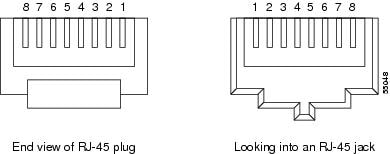
Use a straight-through or cross-over cable to connect to the backplane Ethernet connections of an ONS 15600. Use a straight-through cable to connect to the faceplate connector of the ONS 15600 TSC card. Use CAT-5 cable RJ-45 T-568B, Color Code (100 Mbps), and a crimping tool. Figure 1-17 shows the layout of an RJ-45 connector.

Figure 1-17 RJ-45 Pin Numbers

Figure 1-18 shows the layout of a straight-through cable.

Figure 1-18 Straight-Through Cable Layout

Table 1-24 shows the straight-through cable pinout.

Table 1-24 Straight-Through Cable Pinout 

Pin
Color
Pair
Name
Pin

1

White/Orange

2

Transmit Data +

1

2

Orange

2

Transmit Data -

2

3

White/Green

3

Receive Data +

3

4

Blue

1

4

5

White/Blue

1

5

6

Green

3

Receive Data -

6

7

White/Brown

4

7

8

Brown

4

8


Figure 1-19 shows the layout of a cross-over cable.

Figure 1-19 Crossover Cable Layout

Table 1-25 shows the cross-over cable pinout.

Table 1-25 Crossover Cable Pinout 

Pin
Color
Pair
Name
Pin

1

White/Orange

2

Transmit Data +

3

2

Orange

2

Transmit Data -

6

3

White/Green

3

Receive Data +

1

4

Blue

1

4

5

White/Blue

1

5

6

Green

3

Receive Data -

2

7

White/Brown

4

7

8

Brown

4

8


Note Odd-numbered pins always connect to a white wire with a colored stripe.


1.9.3  Optical Traffic Card Transmit and Receive Levels


Step 1 Each optical traffic card has connectors on its faceplate that contain both transmit and receive ports. Table 1-26 shows the optical power levels for the transmit and receive ports of the optical traffic cards.

Table 1-26 Optical Transmit and Receive Levels 

Card
Transmit
Receive
Minimum
Maximum
Minimum
Maximum

OC48 L16 1550

-2 dBm

+3 dBm

-28 dBm

-9 dBm

OC192 L4 1550

+4 dBm

+7 dBm

-22 dBm

-9 dBm

OC48 SR16 1310

-10 dBm

-3 dBm

-18 dBm

-3 dBm

OC192 SR4 1310

-6 dBm

-1 dBm

-11 dBm

-1 dBm

ASAP SFPs

ONS-SE-Z1
(Supports OC-3 SR-1, OC-12 SR-1, OC-48 IR-1, or GE LX)

ONS-SI-155-L2 (Supports OC-3 LR-2)

ONS-SI-622-L2: (Supports OC-12 LR-2)

ONS-SE-2G-L2: (Supports OC-48 LR-2)

-5.0 dBm

-15


-5.0


-2.0

0 dBm

-8.0


0


3.0

-231
-192
-183

-28


-34


-28

-31
-32
03

-8


-10


-9

1 155.52/622.08 Mbps

2 1250 Mbps

3 2488.32 Mbps


The CTC Maintenance > Transceiver tab shows the optical power transmitted (OPT) and optical power received (OPR) levels.


Note CTC might show OPT levels at 1 dBm more or less than the actual card OPT level.


1.10  Power Supply Problems

This section provides the a procedure for troubleshooting power supply difficulties.


Note For information about power consumption for nodes and cards, refer to the Cisco ONS 15600 Reference Manual.


Symptom    Loss of power or low voltage, resulting in a loss of traffic.

Table 1-27 describes the potential causes of the symptom and the solutions.

Table 1-27 Power Supply Problems

Possible Problem
Solution

A loss of power or low voltage reading.

The ONS 15600 requires a constant source of DC power to properly function. Input voltage range is from -40.5 VDC to -72 VDC.

A newly-installed ONS 15600 that is not properly connected to its power supply will not operate. Power problems can be confined to a specific ONS 15600 or affect several pieces of equipment on the site.

A loss of power or low voltage can result in a loss of traffic.

See the "Isolate the Cause of Power Supply Problems" procedure.

An improperly connected power supply.


Caution Operations that interrupt power supply or short the power connections to the ONS 15600 are service-affecting.


Warning The power supply circuitry for the equipment can constitute an energy hazard. Before you install or replace the equipment, remove all jewelry (including rings, necklaces, and watches). Metal objects can come into contact with exposed power supply wiring or circuitry inside the equipment. This could cause the metal objects to heat up and cause serious burns or weld the metal object to the equipment. Statement 207


Warning Static electricity can damage electro-optical modules. While handling electro-optical module, wear a grounding wrist strap to discharge the static buildup. Wrist straps are designed to prevent static electricity damage to equipment. Statement 312


1.10.0.1  Isolate the Cause of Power Supply Problems


Step 1 If a single ONS 15600 show signs of fluctuating power or power loss:

a. Verify that the -48 VDC power terminals are properly connected to the power distribution unit (PDU).

b. Verify that the power cable is in good condition.

c. Verify that the power cable connections are properly crimped.

d. Verify that 50A circuit breakers are used in the PDU.

e. Verify that the circuit breakers are not blown or tripped.

f. Verify that a rack-ground cable attaches to the frame-ground terminal (FGND) on the ONS 15600. Connect this cable to the ground terminal according to local site practice.

g. Verify that the DC power source has enough capacity to carry the power load.

h. If the DC power source is battery-based:

Check that the output voltage is in the specified range from -40.5 VDC to -72 VDC.

Check the age of the batteries. Battery performance decreases with age.

Check for opens and shorts in batteries, which might affect power output.

If brownouts occur, the power load and fuses might be too high for the battery plant.

Step 2 If multiple pieces of site equipment show signs of fluctuating power or power loss:

a. Check the uninterruptible power supply (UPS) or rectifiers that supply the equipment. Refer to the UPS manufacturer's documentation for specific instructions.

b. Check for excessive power drains caused by other equipment, such as generators.

c. Check for excessive power demand on backup power systems or batteries when alternate power sources are used.