Downloads |
 Feedback Feedback
|
Table Of Contents
5.2.2 Synchronization Status Messaging
Security and Timing
This chapter provides information about Cisco ONS 15327 user security and SONET timing. To provision security and timing, refer to the Cisco ONS 15327 Procedure Guide.
Chapter topics include:
5.1 Users and Security
The CISCO15 ID is provided with the ONS 15327 system, but this user ID is not prompted when you sign into CTC. This ID can be used to set up other ONS 15327 users. (To do this, complete the "Create Users and Assign Security" procedure in the Cisco ONS 15327 Procedure Guide.)
You can have up to 500 user IDs on one ONS 15327. Each Cisco Transport Controller (CTC) or TL1 user can be assigned one of the following security levels:
•
Retrieve—Users can retrieve and view CTC information but cannot set or modify parameters.
•
•
•
By default, multiple concurrent user ID sessions are permitted on the node, that is, multiple users can log into a node using the same user ID. However, you can provision the node to allow only a single login per user and prevent concurrent logins for all users.
Note
5.1.1 Security Requirements
Table 5-1 shows the actions that each user privilege level can perform in node view.
Table 5-1 ONS 15327 Security Levels—Node View
Alarms
—
Synchronize/Filter/Delete Cleared Alarms
X
X
X
X
Conditions
—
Retrieve/Filter
X
X
X
X
History
Session
Filter
X
X
X
X
Node
Retrieve/Filter
X
X
X
X
Circuits
—
Create/Edit/Delete
—
—
X
X
Filter/Search
X
X
X
X
Provisioning
General
General: Edit
—
—
Partial1
X
Power Monitor: Edit
—
—
X
X
EtherBridge
Spanning trees: Edit
—
—
X
X
Network
General: All
—
—
—
X
Static Routing: Create/Edit/ Delete
—
—
X
X
OSPF: Create/Edit/Delete
—
—
X
X
RIP: Create/Edit/Delete
—
—
X
X
Proxy: Create/Edit/Delete
—
—
—
X
Firewall: Create/Edit/Delete
—
—
—
X
Protection
Create/Delete/Edit
—
—
X
X
View
X
X
X
X
BLSR
All
—
—
X
X
Security
Users: Create/Delete/Clear Security Intrusion
—
—
—
X
Users: Change
Same user
Same user
Same user
All users
Active Logins: Logout
—
—
—
X
Policy/Access/Legal Disclaimer: Edit
—
—
—
X
SNMP
Trap destinations/Selected Destination: Create/Edit/Delete
—
—
X
X
Trap destinations/Selected Destination: View
X
X
X
X
Comm Channels
SDCC/Provisionable Patchcords: Create/Edit/Delete
—
—
X
X
Timing
General/BITS Facilities: Edit
—
—
X
X
Alarm Profiles
Alarm Behavior: Edit
—
—
X
X
Alarm Profile Editor: Store/Delete2
—
—
X
X
Alarm Profile Editor: New/Load/Compare/Available/Usage
X
X
X
X
Defaults
Edit/Import
—
—
—
X
Export
X
X
X
X
Inventory
—
Delete
—
—
X
X
Reset
—
X
X
X
Maintenance
Database
Backup
—
X
X
X
Restore
—
—
—
X
EtherBridge
Spanning Trees: View
X
X
X
X
MAC Table: Retrieve
X
X
X
X
MAC Table: Clear/Clear All
—
X
X
X
Trunk Utilization: Refresh
X
X
X
X
Circuits: Refresh
X
X
X
X
Protection
Switch/Lock out/Lockon/Clear/ Unlock
—
X
X
X
BLSR
West/East Switches
—
X
X
X
Software
Download
—
X
X
X
Activate/Revert
—
—
—
X
Cross-Connect
Resource Usage: Delete/Refresh
—
—
X
X
Overhead XConnect
View
X
X
X
X
Diagnostic
Retrieve/Lamp Test
—
X
X
X
Timing
Source: Edit
—
X
X
X
Report: View/Refresh
X
X
X
X
Audit
Retrieve/Archive
—
—
—
X
Routing Table
Retrieve
X
X
X
X
RIP Routing Table
Retrieve
X
X
X
X
Test Access
Read-only
X
X
X
X
1 Provisioner user cannot change node name, contact, location, or AIS-V insertion on STS-1 signal degrade (SD) parameters.
2 The action buttons in the subtab are active for all users, but the actions can be completely performed only by the users assigned with the required security levels.
Table 5-2 shows the actions that each user privilege level can perform in network view.
Table 5-2 ONS 15327 Security Levels—Network View
Alarms
—
Synchronize/Filter/Delete cleared alarms
X
X
X
X
Conditions
—
Retrieve/Filter
X
X
X
X
History
—
Filter
X
X
X
X
Circuits
—
Create/Edit/Delete/Filter
—
Partial
X
X
Search
X
X
X
X
Provisioning
Security
Users: Create/Delete
—
—
—
X
Users: Change
Same User
Same User
Same User
All Users
Active logins: Logout
—
—
—
X
Policy: Change
—
—
—
X
Alarm Profiles
Store/Delete1
—
—
X
X
New/Load/Compare/Available/Usage
—
X
X
X
BLSR
Create/Delete/Edit/Upgrade
—
—
X
X
Overhead Circuits
Create/Delete/Edit/Merge
—
—
X
X
Search
X
X
X
X
Maintenance
Software
Download/Cancel
—
X
X
X
1 The action buttons in the subtab are active for all users, but the actions can be completely performed only by the users assigned with the required security levels.
5.1.2 Security Policies
Users with Superuser security privilege can provision security policies on the ONS 15327. These security policies include idle user timeouts, password changes, password aging, and user lockout parameters. In addition, a Superuser can access the ONS 15327 through the XTC RJ-45 port, the backplane LAN connection, or both.
5.1.2.1 Idle User Timeout
Each ONS 15327 CTC or TL1 user can be idle during his or her login session for a specified amount of time before the CTC window is locked. Timed-out users must re-enter their password to access the CTC session. The lockouts prevent unauthorized users from making changes. Higher-level users have shorter default idle periods and lower-level users have longer or unlimited default idle periods, as shown in Table 5-3. The user idle period can be modified by a Superuser; refer to the Cisco ONS 15327 Procedure Guide for instructions.
Table 5-3 ONS 15327 Default User Idle Times
Superuser
15 minutes
Provisioning
30 minutes
Maintenance
60 minutes
Retrieve
Unlimited
5.1.2.2 User Password, Login, and Access Policies
Superusers can view real-time lists of users who are logged into CTC or TL1 user logins by node. Superusers can also provision the following password, login, and node access policies.
•
•
•
•
In addition, a Superuser can select secure shell (SSH) instead of Telnet at the CTC Provisioning > Security > Access tabs. SSH is a terminal-remote host Internet protocol that uses encrypted links. It provides authentication and secure communication over unsecure channels. Port 22 is the default port and cannot be changed.
5.1.2.3 Audit Trail
Audit trails prove useful for maintaining security, recovering lost transactions, and enforcing accountability. Accountability refers to tracing user activities; that is, associating a process or action with a specific user.
The ONS 15327 maintains a 640-entry, human-readable audit trail of user or system actions such as login, logout, circuit creation or deletion, and user- or system-generated actions. Login events include authorized Cisco logins using the ONS 15454 command line interface or the graphical user interface named Cisco Transport Controller (CTC). You can move the log to a local or network drive for later review. The ONS 15327 generates an event to indicate when the log is 80 percent full, and another event to indicate that the oldest log entries are being overwritten.
Table 5-4 contains the columns listed in Audit Trail window.
5.2 Node Timing
SONET timing parameters must be set for each ONS 15327. Each ONS 15327 independently accepts its timing reference from one of three sources:
•
•
•
You can set ONS 15327 timing to one of three modes: external, line, or mixed. If timing is coming from the BITS port, set ONS 15327 timing to external. If the timing comes from an OC-N card, set the timing to line. Typical ONS 15327 networks have the following timing configurations:
•
•
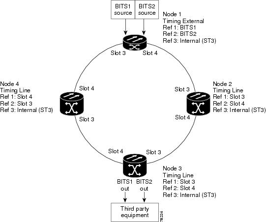
You can set three timing references for each ONS 15327. The first two references are typically two BITS-level sources, or two line-level sources optically connected to a node with a BITS source. The third reference is usually assigned to the internal clock provided on every ONS 15327 XTC card. However, if you assign all three references to other timing sources, the internal clock is always available as a backup timing reference. The internal clock is a Stratum 3 (ST3), so if an ONS 15327 node becomes isolated, timing is maintained at the ST3 level.
The CTC Maintenance > Timing > Report tabs show current timing information for an ONS 15327, including the timing mode, clock state and status, switch type, and reference data.
Caution
5.2.1 Network Timing Example
Figure 5-1 shows an example of an ONS 15327 network timing setup. Node 1 is set to external timing. Two references are set to BITS, and the third reference is set to internal. The BITS output pins on the MIC cards of Node 3 provide timing to outside equipment, such as a digital access line access multiplexer.
Figure 5-1 ONS 15327 Timing Example
5.2.2 Synchronization Status Messaging
Synchronization status messaging (SSM) is a SONET protocol that communicates information about the quality of the timing source. SSM messages are carried on the S1 byte of the SONET line layer. They enable SONET devices to automatically select the highest quality timing reference and to avoid timing loops.
SSM messages are either Generation 1 or Generation 2. Generation 1 is the first and most widely deployed SSM message set. Generation 2 is a newer version. If you enable SSM for the ONS 15327, consult your timing reference documentation to determine which message set to use. Table 5-5 and Table 5-6 show the Generation 1 and Generation 2 message sets.