Downloads |
 Feedback Feedback
|
Table Of Contents
8.2.2 Synchronization Status Messaging
Security and Timing
This chapter provides information about Cisco ONS 15454 users and SONET timing. To provision security and timing, refer to the Cisco ONS 15454 Procedure Guide.
Chapter topics include:
8.1 Users and Security
The CISCO15 ID is provided with the ONS 15454 system, but this user ID is not prompted when you sign into CTC. This ID can be used to set up other ONS 15454 users. (To do this, complete the "Create Users and Assign Security" procedure in the Cisco ONS 15454 Procedure Guide.)
You can have up to 500 user IDs on one ONS 15454. Each Cisco Transport Controller (CTC) or TL1 user can be assigned one of the following security levels:
•
Retrieve—Users can retrieve and view CTC information but cannot set or modify parameters.
•
•
•
Each created user ID can be active on a network element (NE) in a single or multiple occurrence. If you provision the user ID to be active in a single occurrence (in node view Provisioning > Security > Policy tabs, Single Session per User check box), this means that if one user is logged into an NE as CISCO15, no one else can log into that NE as CISCO15. The default setting is to allow multiple concurrent User ID sessions.
Table 8-1 shows the actions that each user privilege level can perform in node view.
Note
A Superuser can perform ONS 15454 user management tasks from the network or node (default login) view. In network view you can add, edit, or delete users from multiple nodes at one time. If you perform user management tasks in node view you can only add, edit, or delete users from that node.
Each ONS 15454 CTC or TL1 user can be idle during his or her login session for a specified amount of time before the CTC window is locked. The lockouts prevent unauthorized users from making changes. Higher-level users have shorter default idle periods and lower-level users have longer or unlimited default idle periods, as shown in Table 8-2. The user idle period can be modified by a Superuser while completing the "Modify Users and Change Security" procedure in the Cisco ONS 15454 Procedure Guide.
Table 8-2 ONS 15454 Default User Idle Times
Superuser
15 minutes
Provisioning
30 minutes
Maintenance
60 minutes
Retrieve
Unlimited
Superusers can change the user idle times on the Provisioning > Security > Policy tab. You can also change security policies that can be edited include:
•
•
•
•
The ONS 15454 maintains a 640-entry, human-readable audit trail of user actions such as login, logout, circuit creation or deletion, etc. You can move the log to a local or network drive for later review. The ONS 15454 generates an event to indicate when the when the log is 80 percent full, and another event to indicate that the oldest log entries are being overwritten.
8.2 Node Timing
SONET timing parameters must be set for each ONS 15454. Each ONS 15454 independently accepts its timing reference from one of three sources:
•
•
•
You can set ONS 15454 timing to one of three modes: external, line, or mixed. If timing is coming from the BITS pins, set ONS 15454 timing to external. If the timing comes from an OC-N card, set the timing to line. In typical ONS 15454 networks:
•
•
You can set three timing references for each ONS 15454. The first two references are typically two BITS-level sources, or two line-level sources optically connected to a node with a BITS source. The third reference is the internal clock provided on every ONS 15454 TCC+/TCC2 card. This clock is a Stratum 3 (ST3). If an ONS 15454 becomes isolated, timing is maintained at the ST3 level.
Caution
8.2.1 Network Timing Example
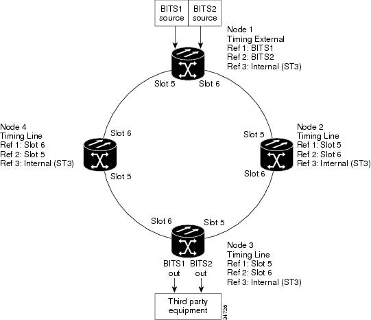
Figure 8-1 shows an ONS 15454 network timing setup example. Node 1 is set to external timing. Two timing references are set to BITS. These are Stratum 1 timing sources wired to the BITS input pins on the Node 1 backplane. The third reference is set to internal clock. The BITS output pins on the backplane of Node 3 are used to provide timing to outside equipment, such as a Digital Access Line Access Multiplexer.
In the example, Slots 5 and 6 contain the trunk (span) cards. Timing at Nodes 2, 3, and 4 is set to line, and the timing references are set to the trunk cards based on distance from the BITS source. Reference 1 is set to the trunk card closest to the BITS source. At Node 2, Reference 1 is Slot 5 because it is connected to Node 1. At Node 4, Reference 1 is set to Slot 6 because it is connected to Node 1. At Node 3, Reference 1 could be either trunk card because they are equal distance from Node 1.
Figure 8-1 ONS 15454 Timing Example
8.2.2 Synchronization Status Messaging
Synchronization status messaging (SSM) is a SONET protocol that communicates information about the quality of the timing source. SSM messages are carried on the S1 byte of the SONET Line layer. They enable SONET devices to automatically select the highest quality timing reference and to avoid timing loops.
SSM messages are either Generation 1 or Generation 2. Generation 1 is the first and most widely deployed SSM message set. Generation 2 is a newer version. If you enable SSM for the ONS 15454, consult your timing reference documentation to determine which message set to use. Table 8-3 and Table 8-4 show the Generation 1 and Generation 2 message sets.