Feedback Feedback
|
Table Of Contents
Configuring Service Point on the Host and Routers
Configuration Notes for VTAM Definitions
Configuring an SWNET Definition
Configuration Notes for Router Definitions
Using VDLC to Obtain a Service Point Connection
Configuring Service Point on the Host and Routers
This appendix provides detailed information about how to configure your VTAM and router definitions to support SNA service point. Two items must be considered when establishing a service point connection from a router to the host:
•
Connecting to the host. This can be done using a MAC address from either an IBM 3745 front-end processor (FEP) or from a CSNA connection on a CIP card. The example provided in this appendix uses a CSNA on the CIP.
•
This appendix contains the following sections:
•
•
Configuration Notes for VTAM Definitions
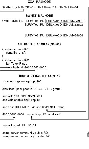
Figure B-1 provides a diagram of a sample VTAM configuration and its corresponding router configuration. If you are using a CIP CSNA connection to the host, then external communication adapter (XCA) definitions are needed (file XCANSP). Use SWNET definitions in VTAM (file CWBTRN001) to define the routers as switched PUs on the host.
Figure B-1 Sample VTAM and Router Configurations for Service Point
Figure B-2 shows the sample network architecture corresponding to the configurations defined in Figure B-1. Figure B-2 shows eight switched PU (SNA service point) routers (IBURMT01-8) that are using the DLSw protocol as the method for establishing an SNA connection to the host.
Figure B-2 Sample Network Configuration
Configuring an XCA Definition
If you are using a CIP CSNA connection to the host, then an external communication adapter (XCA) definition is needed (file XCANSP). The XCA definition in the example in Figure B-1 uses the following arguments:
Configuring an SWNET Definition
Use SWNET definitions (file CWBTRN001) to define the routers as switched PUs on the host. Unlike PUs that are connected by leased line, where you always know what is at the other end of the line, switched PUs can connect to numerous locations of your network. Each router to which you want to establish a service point connection needs to be defined as PU type 2 in a SWNET definition file.
The SWNET definition in Figure B-1 uses the following arguments:
Configuration Notes for Router Definitions
Figure B-1 provides a diagram of a sample router configuration and its corresponding VTAM configuration. The following CIP CSNA definitions on the Neuse router provide access to the host:
Using VDLC to Obtain a Service Point Connection
This section provides information on using virtual data link control (VDLC) as a method of obtaining a service point connection to the host. To configure SNA Service Point to use VDLC, create an SNA VDLC interface.
•
•
•
•
Figure B-1 shows an example of the following commands used in the IBURMT01 router configuration:
source-bridge ring-group 100
Virtually defined source-bridge ring-group number that ties the SNA VDLC interface in with the DLSw network of routers IBURMT01-08.
dlsw local-peer peer-id 171.68.104.36 group 1
DLSw statement for the IBURTM01 router.
sna vdlc 100 0888.8888.8801
Virtual MAC address on source-bridge ring-group 100.
sna vdlc enable-host lsap 12
Command to enable the local SAP. Ready to accept incoming connection attempts from the remote host via VDLC.
sna host IBURMT01 xid-snd 05d88801 rmac 4000.8888.0000 rsap 4 lsap 12 focalpoint
The sna host command uses the following arguments:
•
•
•
•
•
•
sna vdlc start IBURMT01
Statement that initiates a connection from IBURMT01 to the host using VDLC.
snmp-server community public RO
Read-only access for the SNMP protocol to retrieve MIB objects.
snmp-server community private RW
Read-write access for the SNMP protocol to both retrieve and modify MIB objects.
Note