Feedback Feedback
|
Table Of Contents
Using ATM LANE with Catalyst and LightStream 1010 Switches
LANE Hardware Support Requirements
Using ATM LANE with Catalyst and LightStream 1010 Switches
This chapter describes how Asynchronous Transfer Mode (ATM) LAN Emulation (LANE) is used with Catalyst 5000 series and the Catalyst 3000 series switches, and LightStream 1010 switch.
Note
The LANE Manager feature allows you to display and configure LANE information on Catalyst 5000 series switches. On Catalyst 3000 series switches, you can only display LANE information; configuration tools are not available. For this reason, the Create, Configure, Modify, and/or Delete buttons shown might not appear on Catalyst 3000 series switch LANE Manager screens.
LANE Implementation
LANE service emulates the following LAN-specific characteristics:
•
•
•
LANE allows an ATM network to be used as a LAN backbone for hubs, bridges, and Ethernet switches such as Catalyst switches. LANE also allows end stations to communicate through a LAN-to-ATM switch with an ATM-attached device, such as a file server, without requiring the traffic to pass through a more complex device such as a router.
Because LANE connectivity is defined at the MAC layer, upper protocol layer functions of LAN applications can continue unchanged when the devices join emulated LANs (ELANs).
An ATM network can support multiple independent ELANs. Participation of an end system in any of the ELANs is independent of its physical location. The end systems can move easily from one ELAN to another, independent of hardware moves.
LANE Hardware Support Requirements
LANE is supported on Catalyst switches containing ATM modules and on Cisco 7000 and 4500 series routers with ATM Interface Processors (AIPs) installed. LANE implementation requires an ATM switch that supports User-Network Interface (UNI) 3.0 and point-to-multipoint signaling, for example, the LightStream 1010 switch.
LANE Components
Up to 256 ELANs can be set up in an ATM switch cloud. An ATM module for the Catalyst 5000 and Catalyst 3000 series switches can participate in up to 64 ELANs.
LANE is defined on a client-server LAN model as follows:
•
An LEC emulates a LAN interface to higher layer protocols and applications. It forwards data to other LANE components and performs LANE address-resolution functions.
Each LEC is a member of only one ELAN. However, the ATM module in a router or a Catalyst switch can include LECs for multiple ELANs: one LEC for each ELAN of which it is a member.
If a router has LECs for multiple ELANs, the router can route traffic among the ELANs.
Note
•
The LES provides joining, address resolution, and address registration services to the LECs in its ELAN. The LECs can register destination unicast and multicast MAC addresses with the LES. The LES also handles LANE Address Resolution Protocol (ARP) (LE ARP) requests and responses.
Cisco limits one LES for each ELAN.
•
The LANE BUS sequences and distributes multicast and broadcast packets and handles unicast flooding.
One combined LES and BUS is required for each ELAN.
Note
•
The LECS contains the database that determines which ELAN a device belongs to (each LECS can have a different database). Each LEC consults the LECS just once, when it joins an ELAN, to determine which ELAN it should join. The LECS returns the ATM address of the LES for that ELAN.
One LECS is required for each ATM LANE switch cloud.
The LECS database can have the following four types of entries:
•
•
•
•
Note
Note
LANE Communication
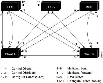
LANE communication is handled by several types of virtual channel connections (VCCs): unidirectional, bidirectional, point-to-point, and point-to-multipoint. Figure E-1 illustrates the various VCC types, including the LECS and the LANE BUS.
Figure E-1 LANE VCC Types
LANE Processes
This section describes the following:
Note
LEC Joining an ELAN
The following process (illustrated in ) normally occurs after an LEC is enabled on the ATM module in a Catalyst 3000 switch:
1
The LEC sets up a connection to the LECS to find the ATM address of the LES for its ELAN (bidirectional, point-to-point link [link 1-7 in ]).
The LEC identifies the LECS by checking the database for the following information:
•
•
•
2
Using the same VCC, the LECS returns the ATM address and the name of the LES for the ELAN of the LEC.
3
4
The LEC sets up a connection to the LES for its ELAN (bidirectional, point-to-point control direct VCC link [link 1-7 in ]) to exchange control traffic. After a link is established between an LEC and LES, it remains up.
5
The LES for the ELAN sets up a connection to the LECS to verify that the LEC is allowed to join the ELAN (bidirectional, point-to-point server configure VCC link [link 11-12 in ]). The LECS configuration request contains the LEC MAC address, its ATM address, and the ELAN name. The LECS checks its database to determine whether the LEC can join that LAN; then it uses the same VCC to inform the server whether the LEC is allowed to join.
6
If allowed, the LES adds the LEC to the unidirectional, point-to-multipoint control distribute VCC link (link 2-8 in ) and confirms the join over the bidirectional, point-to-point control direct VCC link (link 1-7 in ). If disallowed, the LES rejects the join over the bidirectional, point-to-point control direct VCC link (link 1-7 in ).
7
When the LEC sends these packets for the broadcast address, it returns the ATM address of the BUS. The LEC sets up the multicast send VCC link (link 4-9 in ) and the BUS adds the LEC to the multicast forward VCC link (link 5-10 in ) to and from the BUS.
Address Resolution
As communication occurs on the ELAN, each LEC dynamically builds a local LE ARP table. The LE ARP table for the LEC can also have static, preconfigured entries. The LE ARP table maps MAC addresses to ATM addresses.
Note
When an LEC first joins an ELAN, its LE ARP table has no dynamic entries and the LEC has no information about the destinations on or behind its ELAN. To learn about a destination when a packet is to be sent, the LEC begins the following process to find the ATM address corresponding to the known MAC address:
1
2
3
4
5
6
For unknown destinations, the LEC sends a packet to the BUS, which forwards the packet to all LECs. The BUS floods the packet because the destination might be behind a bridge that has not yet learned this particular address.
Multicast Traffic
When an LEC has broadcast, multicast, or unicast traffic with an unknown address to send, the following process occurs:
1
2
This VCC branches at each ATM switch. The switch forwards such packets to multiple outputs. (The switch does not examine the MAC addresses; it simply forwards all packets it receives.)
Addressing
On a LAN, packets are addressed by the MAC-layer address of the destination and source stations. For LANE to have similar functionality, MAC-layer addressing must be supported. Every LEC must have a MAC address. In addition, every LANE component (LES, LEC, BUS, and LECS) must have a unique ATM address.
All LECs on the same interface have different, automatically assigned MAC addresses. These addresses are also used as the end-system identifier (ESI) part of the ATM address (see "LANE ATM Addresses").
LANE ATM Addresses
A LANE ATM address has the same syntax as a network service access point (NSAP), but it is not a network-level address. It consists of the following:
•
•
•
•
•
•
•
ILMI Address Registration
The ATM module for the Catalyst 5000 and Catalyst 3000 series switches and the LightStream 1010 switch uses ILMI (Interim Local Management Interface) registration to build an ATM address and to register this address with the ATM switch. To build an ATM address, the Catalyst 5000 and Catalyst 3000 series switches and the LightStream 1010 switch obtain an ATM address prefix from the ATM switch, and combine the prefix with a MAC address and the selector value of 0 (zero). Once the ATM module determines its ATM address, it uses ILMI registration to register this address with the ATM switch.
VLANs and ELANs
On the Catalyst switch, a virtual LAN (VLAN) is a logical group of end stations, independent of physical location, with a common set of requirements. Currently, these switches support a port-centric VLAN configuration. All end stations connected to ports belong to the same VLAN and are assigned to the same VLAN name. The VLAN name is significant only to the Catalyst 5000 and Catalyst 3000 series switches.
Typical LANE Scenarios
In typical LANE cases, one or more Catalyst 5000 and Catalyst 3000 series switches or Cisco 7000 routers are attached to a LightStream 1010 switch. The LightStream 1010 switch provides connectivity to the broader ATM network switch cloud. Each router is configured to support one or more ELANs. One router is configured to perform the LECS functions. Another router is configured to perform the LES and BUS functions for each ELAN. (One router can perform the LES and BUS functions for several ELANs.) Routers and Catalyst 5000 and Catalyst 3000 series switches can act as an LEC for one or more ELANs.
This section describes two scenarios using Cisco 7000 routers, Catalyst 3000 switches, and a Cisco LightStream 1010 switch in single and multiple ELANs.
Note
Single ELAN Scenario
In a single ELAN scenario, the LANE components might be assigned to a particular department in a company:
•
•
•
•
•
•
Multiple ELAN Scenario
In a multiple ELAN scenario, one ATM switch, two routers, and two Catalyst 3000 series switches are used, but multiple ELANs are configured. Three ELANs are configured on two routers and two Catalyst 3000 series switches for three different departments: Manufacturing, Engineering, and Marketing.
The LANE components are assigned as follows:
•
•
•
•
•
•
•
•
•
•
•
•