Feedback
Table Of Contents
Dial Peer Configuration Examples
Both Connected to the Same Voice Gateway Router
Each Connected to Their Own Voice Gateway Routers Using the G.711 Codec
Each Connected to Their Own Voice Gateway Routers Using the G.729r8 Codec
An Analog Phone and an IP Phone Connected over an IP Network
Two IP Phones Connected via a Voice over Frame Relay Network
Using Digit Manipulation to Overcome the Obstacle of an IP Network Failure
Dial Peer Configuration Examples
This appendix contains a series of configuration examples featuring the minimum required components and critical Cisco IOS command lines extracted from voice gateway configuration files necessary to complete an endpoint-to-endpoint call. Each example is designed to focus on a specific combination of components or configuration concept essential to voice over IP (VoIP) communication. This appendix covers the following topics:
•
An Analog Phone and an IP Phone Connected over an IP Network
•
•
•
Two Analog Phones
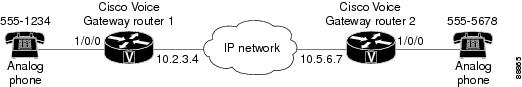
The simplest and most ubiquitous implementation of dial peer configuration involves connecting two standard analog telephones over an IP network. The following two examples illustrate the minimum required configurations necessary to connect two analog phones, where they are attached to the same voice gateway router and where each phone is attached to its own voice gateway router via FXS ports installed in the voice gateway routers in question.
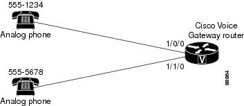
Both Connected to the Same Voice Gateway Router
Figure 17 Two analog phones connected to the same voice gateway router
Voice Gateway Router Configuration File
voice-port 1/0/0!voice-port 1/0/1!!dial-peer voice 1 potsdestination-pattern 5551234port 1/0/0!dial-peer voice 2 potsdestination-pattern 5555678port 1/0/1Each Connected to Their Own Voice Gateway Routers Using the G.711 Codec
Figure 18 Two analog phones each connected to their own voice gateway router
Voice Gateway Router 1 Configuration File
voice-port 1/0/0!dial-peer voice 1 potsdestination-pattern 5551234port 1/0/0!dial-peer voice 10 voipdestination-pattern 5555678session target ipv4:10.5.6.7codec g711ulawVoice Gateway Router 2 Configuration File
voice-port 1/0/0!dial-peer voice 2 potsdestination-pattern 5555678port 1/0/0!dial-peer voice 20 voipdestination-pattern 5551234session target ipv4:10.2.3.4codec g711ulawEach Connected to Their Own Voice Gateway Routers Using the G.729r8 Codec
Voice Gateway Router 1 Configuration File
voice class codec 1codec preference 1 g729r8codec preference 2 g711ulaw!voice-port 1/0/0!voice-port 1/0/1!!dial-peer voice 1 potsdestination-pattern 5551234port 1/0/0!dial-peer voice 2 voipdestination-pattern 5555678voice-class codec 1session target ipv4:10.5.6.7Voice Gateway Router 2 Configuration File
voice class codec 1codec preference 1 g729r8codec preference 2 g711ulaw!voice-port 1/0/0!voice-port 1/0/1!!dial-peer voice 1 potsdestination-pattern 5555678port 1/0/0!dial-peer voice 2 voipdestination-pattern 5551234voice-class codec 1session target ipv4:10.2.3.4Two Fax Machines
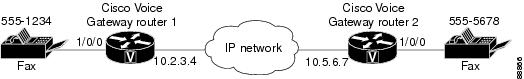
Once the connection between two analog phones over the IP network can be set up, you can then alter the configuration slightly to enable fax communication over the IP network. Figure 19 illustrates the configuration files necessary to establish T.38 Fax Relay functionality over the IP network.
Figure 19 Two fax machines connected via T.38 Fax Relay
Voice Gateway Router 1 Configuration File
interface FastEthernet0/0ip address 10.21.9.4 255.255.255.0!voice-port 1/0/0!voice-port 1/0/1!dial-peer voice 1 potsdestination-pattern 5551234port 1/0/0!dial-peer voice 2 voipdestination-pattern 5555678session target ipv4:10.5.6.7codec g711ulawfax protocol t38 ls-redundancy 0 hs-redundancy 0 fallback ciscofax rate voiceVoice Gateway Router 2 Configuration File
interface FastEthernet0/0ip address 10.21.7.61 255.255.255.0!voice-port 1/0/0!voice-port 1/0/1!dial-peer voice 1 potsdestination-pattern 5555678port 1/0/0!dial-peer voice 2 voipdestination-pattern 5551234voice-class codec 1session target ipv4:10.2.3.4codec g711ulawfax protocol t38 ls-redundancy 0 hs-redundancy 0fax rate voiceAn Analog Phone and an IP Phone Connected over an IP Network
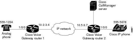
Once you are able to establish the connection of two analog phones over an IP network, you can then expand the scope of configuration coverage to include an analog phone and an IP phone connected over the IP network. The configuration for each of the voice gateway routers is essentially the same as if you were connecting two analog phones; you will need to ensure that you have allowed for a Cisco CallManager server connection to the appropriate Cisco voice gateway router to accommodate the introduction of the IP phone.
Note
Figure 20 An analog phone and an IP phone each connected to their own voice gateway router
Voice Gateway Router 1 Configuration File
voice-port 1/0/0!dial-peer voice 1 potsdestination-pattern 5551234port 1/0/0!dial-peer voice 2 voipdestination-pattern 5555678session target ipv4:10.5.6.7Voice Gateway Router 2 Configuration File
voice-port 1/0/0!dial-peer voice 1 potsdestination-pattern 5555678port 1/0/0!dial-peer voice 2 voipdestination-pattern 5551234session target ipv4:10.2.3.4Two IP Phones Connected via a Voice over Frame Relay Network
The examples thus far in this appendix have described connecting endpoints over an IP network based primarily on Ethernet connections. However, you may find that you must configure a Frame Relay WAN to effectively serve the voice communications demands for your system. Figure 21 and the subsequent Cisco voice gateway router configuration examples illustrate the dial peer configuration and Frame Relay Cisco IOS commands necessary to enable Frame Relay communication across your IP network.
Note
Figure 21 Two IP phones connected over a Frame Relay network
Voice Gateway Router 1 Configuration File
The configuration for this voice gateway features a Cisco 3620 running Cisco IOS Release 12.2(11)T6.
interface Serial0/0ip address 10.2.1.1 255.0.0.0encapsulation frame-relay!voice-port 1/0/0!voice-port 1/0/1!voice-port 1/1/0!voice-port 1/1/1!dial-peer cor custom!dial-peer voice 1 potsdestination-pattern 5551234port 1/0/0!dial-peer voice 1000 voippreference 1destination-pattern 5555678session target ipv4:10.5.6.7Voice Gateway Router 2 Configuration File
The configuration for this voice gateway features a Cisco 3620 running Cisco IOS Release 12.2(15)T.
interface Serial0/0ip address 10.2.3.4 255.0.0.0encapsulation frame-relayclockrate 2000000no fair-queue!voice-port 1/0/0!voice-port 1/0/1!voice-port 1/1/0!voice-port 1/1/1!dial-peer cor custom!dial-peer voice 1 potsdestination-pattern 5555678port 1/0/0!dial-peer voice 2000 voippreference 1destination-pattern 5551234session target ipv4:10.2.3.4Using Digit Manipulation to Overcome the Obstacle of an IP Network Failure
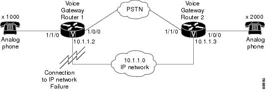
Figure 22 and the subsequent Cisco voice gateway router configuration examples illustrate the dial peer configuration necessary to automatically route an outgoing voice call over the PSTN in the event of a temporary IP network outage. An advantage to this method of setting up and connecting the call over the PSTN (while still originating the transmission from a voice gateway router) is more commonly known as "toll bypass."
Figure 22 Using the PSTN in the event of an IP network failure
Voice Gateway Router 1 Configuration File
The configuration for this voice gateway features a Cisco 3620 running Cisco IOS Release 12.2(15)T.
translation-rule 21Rule 1 ^2 5552!translation-rule 11Rule 1 ^5551 1!interface FastEthernet0/0ip address 10.1.1.2 255.255.255.0duplex autospeed auto!voice-port 1/0/0translate called 11!voice-port 1/0/1!voice-port 1/1/0!voice-port 1/1/1!dial-peer cor custom!dial-peer voice 1 potsdestination-pattern 1000port 1/1/0!dial-peer voice 2000 voippreference 1destination-pattern 2000session target ipv4:10.1.1.3!dial-peer voice 20 potspreference 2destination-pattern 2000translate-outgoing called 21port 1/0/0forward-digits allVoice Gateway Router 2 Configuration File
The configuration for this voice gateway features a Cisco 3620 running Cisco IOS Release 12.2(11)T6.
translation-rule 11Rule 1 ^1 5551!translation-rule 21Rule 1 ^5552 2!interface Ethernet0/0ip address 10.1.1.3 255.255.255.0full-duplex!voice-port 1/0/0!voice-port 1/0/1!voice-port 1/1/0translate called 21!voice-port 1/1/1!dial-peer cor custom!dial-peer voice 1 potsdestination-pattern 2000port 1/0/0!dial-peer voice 1000 voippreference 1destination-pattern 1000session target ipv4:10.1.1.2!dial-peer voice 10 potspreference 2destination-pattern 1000translate-outgoing called 11port 1/1/0forward-digits allCisco and the Cisco Logo are trademarks of Cisco Systems, Inc. and/or its affiliates in the U.S. and other countries. A listing of Cisco's trademarks can be found at www.cisco.com/go/trademarks. Third party trademarks mentioned are the property of their respective owners. The use of the word partner does not imply a partnership relationship between Cisco and any other company. (1005R)
© 2007-2010 Cisco Systems, Inc. All rights reserved.