-
This documentation has been moved
-
Cisco Unified Border Element Features Roadmap
-
Overview of Cisco Unified Border Element
-
Fundamental Cisco Unified Border Element Configuration
-
H.323-to-H.323 Connections on a Cisco Unified Border Element
-
H.323-to-SIP Connections on a Cisco Unified Border Element
-
SIP-to-SIP Connections on a Cisco Unified Border Element
-
Cisco Unified Border Element for H.323 Cisco Unified Communications Manager to H.323 Service Provider Connectivity
-
Configuring Cisco Unified Border Element Videoconferencing
-
 Feedback
Table Of Contents
Fundamental Cisco Unified Border Element Configuration
Prerequisites for Fundamental Cisco Unified Border Element Configuration
Restrictions for Fundamental Cisco Unified Border Element Configuration
Information About Cisco Unified Border Element Features
How to Configure Fundamental Cisco Unified Border Element
Configuring an Ethernet Interface
Configuring a RTP Loopback Interface
Configuring Codec Transparency on a Cisco Unified Border Element
Configuring Codec Transparency for All Dial Peers in a Voice Class
Configuring Codec Transparency for an Individual Dial Peer
Configuring iLBC Codec on a Cisco Unified Border Element
iSAC Codec Support on TDM-IP Voice Gateways and Cisco UBE Platforms
Prerequisites for iSAC Codec Support on TDM-IP Voice Gateways and Cisco UBE Platforms
Restrictions for iSAC Codec Support on Cisco TDM-IP Voice Gateways and Cisco UBE Platforms
Information About iSAC Codec Support on TDM-IP Voice Gateways and Cisco UBE Platforms
iSAC Codec Support on Cisco TDM-IP Voice Gateways and Cisco UBE Platforms Overview
How to Configure iSAC Codec Support on Cisco TDM-IP Voice Gateways and Cisco UBE Platforms
Configuration Examples for iSAC Codec Support on Cisco TDM-IP Voice Gateways and Cisco UBE Platforms
SG3 Fax Support on Cisco TDM-IP Voice Gateways and Cisco UBE Platforms
Prerequisites for SG3 Fax Support on Cisco TDM-IP Voice Gateways and Cisco UBE Platforms
Restrictions for SG3 Fax Support on Cisco TDM-IP Voice Gateways and Cisco UBE Platforms
Information About SG3 Fax Support on Cisco TDM-IP Voice Gateways and Cisco UBE Platforms
How to Configure SG3 Fax Support on Cisco TDM-IP Voice Gateways and Cisco UBE Platforms
Configuration Examples for SG3 Fax Support on Cisco TDM-IP Voice Gateways and Cisco UBE Platforms
Configuring QoS for a Cisco Unified Border Element
Configuring Cisco Unified Border Element for High Utilization
Increase I/O Memory for High Utilization
Manage Ethernet Hold Queue for High Utilization
Configuring Cisco Unified Border Element with OSP
Media Statistics on a Cisco Unified Border Element
Information About Media Statistics in an Cisco Unified Border Element
Configuring Media Statistics in a Cisco Unified Border Element
Configuring Media Statistics in Voice-Service Configuration Mode
Configuring Media Statistics on Dial Peer Configuration Mode
Monitoring Media Statistics in a Cisco Unified Border Element
Voice Quality Enhancements on Cisco Unified Border Element
Configuring Codec Repacketization
Configuring Codec Repacketization the Incoming VoIP Dial Peer
Configuring Codec Repacketization the Outgoing VoIP Dial Peer
Verifying Codec Repacketization
Configuring IP-to-IP Call Gain/Loss Control
Configuring IP-to-IP Call Gain/Loss Control on the Incoming VoIP Dial Peer
Configuring IP-to-IP Call Gain/Loss Control on the Outgoing VoIP Dial Peer
Verifying IP-IP Call Gain/Loss
Configuring Voice Quality Metrics
Verifying Voice Quality Metrics
Troubleshooting and Verifying Fundamental Cisco Unified Border Element Configuration and Operation
Verifying Fundamental Cisco Unified Border Element Configurations
Configuration Examples for Fundamental Cisco Unified Border Element
Cisco Unified Border Element: Example
Local-to-Remote Network Using the Cisco Unified Border Element: Example
Remote-to-Local Network Using the Cisco Unified Border Element: Example
Remote-to-Remote Network Using a Cisco Unified Border Element: Example
Remote-to-Remote Network Using Two Cisco Unified Border Elements: Example
Codec Repacketization: Example
Voice Quality Metrics: Example
Feature Information for Cisco Unified Border Element Configuration Guide
Fundamental Cisco Unified Border Element Configuration
Revised: March 19, 2010First Published: June 19, 2006Last Updated: March 19, 2010This chapter describes fundamental configuration tasks required for Fundamental Cisco Unified Border Element functionality. A Cisco Unified Border Element, in this guide also called an IP-to-IP gateway (IPIPGW), border element (BE), or session border controller, facilitates connectivity between independent VoIP networks by enabling H.323 VoIP and videoconferencing calls from one IP network to another. This gateway performs most of the same functions of a PSTN-to-IP gateway, but typically joins two IP call legs, rather than a PSTN and an IP call leg.
Activation
Cisco Product Authorization Key (PAK)—A Product Authorization Key (PAK) is required to configure some of the features described in this guide. Before you start the configuration process, please register your products and activate your PAK at the following URL http://www.cisco.com/go/license.
Your software release may not support all the features documented in this module. For the latest feature information and caveats, see the release notes for your platform and software release. To find information about the features documented in this module, and to see a list of the releases in which each feature is supported, see the "Cisco Unified Border Element Features Roadmap" section on page 1.
Use Cisco Feature Navigator to find information about platform support and Cisco IOS and Catalyst OS software image support. To access Cisco Feature Navigator, go to http://www.cisco.com/go/cfn. An account on Cisco.com is not required.
For more information about Cisco IOS voice features, see the entire Cisco IOS Voice Configuration Library—including feature documents, and troubleshooting information—at http://www.cisco.com/en/US/docs/ios/12_3/vvf_c/cisco_ios_voice_configuration_library_glossary/vcl.htm.
Contents
•
•
•
•
•
•
Prerequisites for Fundamental Cisco Unified Border Element Configuration
•
•
•
Note
Restrictions for Fundamental Cisco Unified Border Element Configuration
•
•
•
•
•
•
•
•
Information About Cisco Unified Border Element Features
Gateway feature benefits include the following:
•
•
•
•
•
•
•
•
How to Configure Fundamental Cisco Unified Border Element
This section contains the following tasks:
•
•
•
•
•
•
•
•
•
•
•
•
Configuring an Ethernet Interface
You can configure the Cisco Unified Border Element feature to operate with either a single Ethernet interface for all incoming, outgoing, and via-zone gatekeeper traffic or two Ethernet interfaces for signaling and media streams (optional but highly recommended for single-interface configurations). To configure an Ethernet interface, perform the steps in this section.
SUMMARY STEPS
1.
2.
3.
4.
5.
DETAILED STEPSExamples
The following example shows a configuration that uses a single Ethernet interface for all traffic:
interface FastEthernet0/1ip address 10.16.8.6 255.255.0.0no ip redirectsip route-cache same-interfacespeed autofull-duplexh323-gateway voip interfaceh323-gateway voip id 7206-vgk1 ipaddr 10.16.8.71 1719h323-gateway voip h323-id 3660-hud1h323-gateway voip tech-prefix 1#h323_gateway voip bind srcaddr 10.16.8.6Configuring a RTP Loopback Interface
The Cisco Unified Border Element supports configuration of an RTP loopback dial peer for use in verifying and troubleshooting H.323 networks. When a call encounters an RTP loopback dial peer, the gateway automatically signals call connect and loops all voice data back to the source. In contrast to normal calls through the VoIP-to-VoIP gateway, RTP loopback calls consist of only one call leg.
To configure a RTP loopback interface, perform the steps in this section.
SUMMARY STEPS
1.
2.
3.
4.
5.
6.
7.
8.
DETAILED STEPSExamples
Using a Single Dial Peer on a Cisco Unified Border Element
Router(config)# dial-peer voice 5550199 voipRouter(config-dial-peer)# incoming called-number 5550199Router(config-dial-peer)# destination-pattern 5550199Router(config-dial-peer)# codec g711ulawRouter(config-dial-peer)# session target loopback:rtpUsing Separate Dial Peers on a Cisco Unified Border Element
dial-peer voice 5550188 voipincoming called-number 5550188session target rascodec g711ulaw!dial-peer voice 5550182 voipdestination-pattern 5550188session target loopback:rtpUsing a Codec Preference List to Support Additional Codecs
voice class codec 1
codec preference 1 g711ulawcodec preference 2 g729r8dial-peer voice 5429999 voipincoming called-number 5550199destination-pattern 5550199voice-class codec 1session target loopback:rtpConfiguring Codec Transparency on a Cisco Unified Border Element
Codec transparency enables the Cisco Unified Border Element to pass codec capabilities between endpoints. If you configure transparency, the Cisco Unified Border Element uses the codec that was specified by the endpoints for setting up a call.
To configure codec transparency on an Cisco Unified Border Element, perform the steps in this section. This section contains the following subsections:
•
•
Restrictions
•
•
•
•
Configuring Codec Transparency for All Dial Peers in a Voice Class
To configure codec transparency for all dial peers in a voice class, perform the steps in this section.
SUMMARY STEPS
1.
2.
3.
4.
5.
6.
7.
8.
DETAILED STEPSConfiguring Codec Transparency for an Individual Dial Peer
To configure codec transparency for an individual dial peer, perform the steps in this section.
Restrictions
If you plan to configure both incoming and outgoing dial peers, you must specify the transparent codec on the incoming dial peer.
SUMMARY STEPS
1.
2.
3.
4.
5.
DETAILED STEPSExamples
The following example shows an inbound and outbound dial peer on the same tag in which the inbound dial peer is configured with the transparent codec, and the outbound dial peer is configured with the filter codec:
dial-peer voice 1 voipincoming called-number .Tdestination-pattern .Tsession target rascodec transparentThe following example shows separate tags for the inbound and outbound dial peers:
dial-peer voice 1 voipdestination-pattern .Tsession target rascodec transparentdial-peer voice 2 voipincoming called-number .Tcodec transparentdestination-pattern .Tsession target rasThe following example shows filtering of high-bandwidth codecs applied to dial peer 1. With this configuration, codecs other than those specified are disallowed.
voice class codec 1codec preference 1 g729br8codec preference 2 g723r53codec preference 3 g723r68dial-peer voice 1 voipvoice-class codec 1The following shows a different filtering configuration. With this configuration, codecs other than g729r8 are disallowed.
dial-peer voice 1 voipdestination-pattern .Tsession target rasConfiguring iLBC Codec on a Cisco Unified Border Element
The internet Low Bitrate Codec (iLBC) is a standard, high-complexity speech codec that is suitable for robust voice communication over IP. iLBC has built-in error correction functionality that helps the codec perform in networks with a high-packet loss.
Note
Additional information and configuration of the iLBC code on an Cisco Unified Border Element can be found at the following links:
•
http://www.cisco.com/univercd/cc/td/doc/product/software/ios123/123cgcr/vvfax_c/int_c/dpeer_c
/dp_ovrvw.htm#1035124•
http://www.cisco.com/univercd/cc/td/doc/product/software/ios123/123cgcr/vvfax_c/int_c/dpeer_c
/dp_confg.htmiSAC Codec Support on TDM-IP Voice Gateways and Cisco UBE Platforms
This section provides information about Cisco internet Speech Audio Codec (iSAC) support on Cisco Time Division Multiplexing-Internet Protocol (TDM-IP) Voice Gateways and Cisco Unified Border Element (Cisco UBE) platforms.
Contents
•
•
•
•
Prerequisites for iSAC Codec Support on TDM-IP Voice Gateways and Cisco UBE Platforms
The following prerequisites apply to this feature:
•
–
–
–
•
•
Restrictions for iSAC Codec Support on Cisco TDM-IP Voice Gateways and Cisco UBE Platforms
The following restrictions apply to this feature:
•
Information About iSAC Codec Support on TDM-IP Voice Gateways and Cisco UBE Platforms
To configure iSAC Codec Support on Cisco TDM-IP Voice Gateways and Cisco UBE Platforms, you should understand the following concept:
•
iSAC Codec Support on Cisco TDM-IP Voice Gateways and Cisco UBE Platforms Overview
The iSAC codec is an adaptive VoIP codec specially designed to deliver wideband sound quality in both low- and high-bit rate applications. The iSAC codec automatically adjusts the bit-rate for the best quality or a fixed bit rate can be used if the network characteristics are known. This codec is designed for wideband VoIP communications. The iSAC codec offers better quality with reduced bandwidth for sideband applications.
How to Configure iSAC Codec Support on Cisco TDM-IP Voice Gateways and Cisco UBE Platforms
This section contains the following procedures:
•
•
•
Configuring iSAC Codec Support Under VoIP Dial Peer Configuration Mode
Perform the following tasks to configure the use of the iSAC codec for an individual VoIP dial peer. Note that there are other keywords and arguments for the some of the commands in this procedure, but they are not relevant to the configuration of the iSAC codec, so they have been omitted for brevity and clarity.
SUMMARY STEPS
1.
2.
3.
4.
5.
DETAILED STEPSConfiguring iSAC Codec Support Under Voice-Class Configuration Mode
To configure support for the iSAC codec under voice-class configuration mode, complete the following tasks.
SUMMARY STEPS
1.
2.
3.
4.
5.
6.
7.
8.
DETAILED STEPSConfiguring iSAC Codec Support Under DSP Farm Profile Configuration Mode
To configure support for the iSAC codec under DSP farm profile configuration mode, complete the following tasks.
SUMMARY STEPS
1.
2.
3.
4.
5.
6.
7.
8.
9.
or
maximum sessions {hardware | software} number
10.
11.
DETAILED STEPSConfiguration Examples for iSAC Codec Support on Cisco TDM-IP Voice Gateways and Cisco UBE Platforms
This section provides the following configuration example:
•
Configuring iSAC Codec Support on Cisco TDM-IP Voice Gateways and Cisco UBE Platforms
The following example shows a sample configuration for iSAC codec support configured under DSP farm profile on a Cisco 2811:
Router# show running-configBuilding configuration...Current configuration : 2108 bytes^M!! Last configuration change at 16:00:26 PDT Mon Mar 15 2010!version 15.1service timestamps debug datetime msec localtime show-timezoneservice timestamps log datetime msec localtime show-timezoneno service password-encryption!hostname Router!boot-start-markerboot-end-marker!!card type t1 0 0logging buffered 5120000no logging consoleenable password xxx!no aaa new-modelmemory-size iomem 5clock timezone PDT -7network-clock-participate wic 0!ip source-route!!ip cef!!no ip domain lookupip host xxxx 223.255.254.254no ipv6 cefmultilink bundle-name authenticated!!voice-card 0dsp services dspfarm!!!license udi pid CISCO2811 sn xxxxxxxxxxxarchivelog confighidekeys!redundancy!!controller T1 0/0/0shutdowncablelength long 0db!!interface FastEthernet0/0ip address 10.2.107.1 255.255.0.0duplex autospeed auto!interface FastEthernet0/1ip address 192.168.20.1 255.255.255.0no ip proxy-arpduplex autospeed auto!ip forward-protocol nd!!no ip http serverip route 10.0.0.0 0.0.0.0 10.2.0.1ip route 10.0.0.0 255.0.0.0 10.2.0.1ip route 192.0.0.0 255.0.0.0 FastEthernet0/1ip route 223.0.0.0 255.0.0.0 10.2.0.1ip route 223.255.254.254 255.255.255.255 10.2.0.1!!control-plane!!!mgcp fax t38 ecm!sccp local FastEthernet0/0sccp ccm 10.2.105.100 identifier 1 version 7.0sccp!sccp ccm group 1bind interface FastEthernet0/0associate ccm 1 priority 1associate profile 102 register xxxxUXCODEassociate profile 101 register CFBxxxxconf!dspfarm profile 102 transcode universalcodec g711ulawcodec g711alawcodec g729ar8codec g729abr8codec g729r8codec g722-64codec ilbccodec isaccodec g729br8maximum sessions 5associate application SCCP!dspfarm profile 101 conferencecodec g711ulawcodec g711alawmaximum sessions 2associate application SCCP!!!line con 0exec-timeout 0 0line aux 0line vty 0 4session-timeout 300exec-timeout 0 0password labno logintransport input all!exception data-corruption buffer truncatescheduler allocate 20000 1000endSG3 Fax Support on Cisco TDM-IP Voice Gateways and Cisco UBE Platforms
This section provides information about SG3 Fax Support on Cisco Time Division Multiplexing-Internet Protocol (TDM-IP) Voice Gateways and Cisco Unified Border Element (Cisco UBE) platforms. The enhancements described in this section provide T.38 fax relay and fax pass-through on TDM-IP voice gateways and on Cisco UBE platforms.
Contents
•
•
•
Prerequisites for SG3 Fax Support on Cisco TDM-IP Voice Gateways and Cisco UBE Platforms
The following prerequisites apply to this feature:
•
–
–
–
•
•
Restrictions for SG3 Fax Support on Cisco TDM-IP Voice Gateways and Cisco UBE Platforms
The following restrictions apply to this feature:
•
•
Information About SG3 Fax Support on Cisco TDM-IP Voice Gateways and Cisco UBE Platforms
To configure SG3 Fax Support on Cisco TDM-IP Voice Gateways and Cisco UBE Platforms, you should understand the following concepts:
•
SG3 Fax Support on Cisco TDM-IP Voice Gateways and Cisco UBE Platforms Overview
This feature provides support for V.34 fax relay based on the ITU Specification T.38 version 3 (04/2007) and for fax pass-through at SG3 speed. Prior to Cisco IOS Release 15.1(1)T, SG3-to-SG3 calls would fail because the V.34 modulation was not supported. A fallback solution allowed SG3-to-SG3 connections to be made, but the transmission speed was set to G3 levels.
For T.38 fax sessions to operate at SG3 speeds, all the endpoints involved must support T.38 Version 3 (v3) configuration and have negotiated T.38 v3. For example:
Originating Gateway(T.38 v3)—IP-(T.38 v3)Cisco UBE(T.38 v3)-IP—Terminating Gateway(T.38 v3)
In this context, all currently supported Cisco UBE T.38 flows (H.323-H.323, H.323-SIP and SIP-SIP) are supported in Release 15.1(1)T. However, in topologies where at least one endpoint has a T.38 v0 configuration, the Cisco UBE configuration must be T.38 v0 (the lowest common version). Any other combination of T.38 v3 or v0 configuration involved in the Cisco UBE topologies is not supported.
When two endpoints are involved in negotiating the T.38 parameter, the mandatory parameter is the "FaxVersion." That is, when one of the endpoints supports Version 0 (v0), the resulting session operates as a v0 session. As long as Cisco UBE is configured for the lowest common version of the traffic expected, calls are completed successfully.
The information for supported calls is summarized in Table 1 and Table 2.
Table 1 Supported Call Flows with Mixed Endpoints at v0 and v3 Speeds
v0
v0
v0
v0
v3
v0
v3
v0
v0
v3
v3
v3
Table 2 Supported Call Flows with Mixed Endpoints and Cisco UBE
v0
v0
v0
v0
v0
v0
v3
v0
v3
v0
v0
v0
v3
v3
v3
v3
How to Configure SG3 Fax Support on Cisco TDM-IP Voice Gateways and Cisco UBE Platforms
This section contains the following procedures:
•
•
Configuring Fax Pass-Through
To enable the SG3 Fax Support on Cisco TDM-IP Voice Gateways and Cisco UBE Platforms feature, configure fax pass-through as described in the Configuring Fax Pass-Through section of the Cisco IOS Fax, Modem, and Text Support over IP Configuration Guide.
Configuring T.38 Fax Relay
Perform one of the following tasks to configure T.38 fax relay at the dial-peer level or the global level under voice service voip:
•
•
Configuring One or More Individual VoIP Dial Peers for T.38 Fax Relay
Perform this task to configure T.38 fax relay for an individual VoIP dial peer.
SUMMARY STEPS
1.
2.
3.
4.
5.
6.
7.
DETAILED STEPSConfiguring T.38 Fax Relay on VoIP Dial Peers Globally
Perform this task to configure T.38 fax relay globally for previously defined VoIP dial peers.
Note
SUMMARY STEPS
1.
2.
3.
4.
DETAILED STEPSConfiguration Examples for SG3 Fax Support on Cisco TDM-IP Voice Gateways and Cisco UBE Platforms
This section provides the following configuration example:
Configuring SG3 Fax Support for T.38 protocol on Cisco TDM-IP Voice Gateways and Cisco UBE Platforms: Example
The following example shows how to configure SG3 Fax Support for the T.38 protocol on the Cisco TDM-IP Voice Gateways and Cisco UBE Platforms feature:
!voice service voipfax protocol t38 version 3 ls-redundancy 0 hs-redundancy 0 fallback cisco!!interface FastEthernet0/0ip address 1.2.103.1 255.255.0.0!!!dial-peer voice 100 voipdestination-pattern 1.....session target ipv4:1.2.103.3dtmf-relay h245-signalfax protocol t38 version 3 ls-redundancy 0 hs-redundancy 0 fallback cisco!dial-peer voice 200 voipdestination-pattern 2.....session protocol sipv2session target ipv4:1.2.103.3dtmf-relay rtp-ntefax protocol pass-through g711ulaw!dial-peer voice 6789 voipdestination-pattern 6789session target ipv4:1.2.102.2dtmf-relay rtp-ntefax protocol pass-through g711ulaw!!sip-uaConfiguring QoS for a Cisco Unified Border Element
To assign QoS differentiated services code points (DSCP) for H.323 calls through the Cisco Unified Border Element, perform the steps in this section.
Note
•
•
SUMMARY STEPS
1.
2.
3.
4.
5.
6.
DETAILED STEPSConfiguring Cisco Unified Border Element for High Utilization
For high-utilization configurations, the Cisco Unified Border Element may require a higher percentage of memory than that which is made available by default during bootup. Additionally, high-utilization configurations may experience an increase in dropped packets.
To configure Cisco Unified Border Element for high utilization, perform the steps in this section. This section contains the following subsections:
•
•
Increase I/O Memory for High Utilization
To increase the amount of memory available to the Cisco Unified Border Element, perform the steps in this section.
Prerequisites
Determine if sufficient I/O memory is available by using the show memory command:
Note
SUMMARY STEPS
1.
2.
3.
4.
DETAILED STEPSManage Ethernet Hold Queue for High Utilization
Some traffic patterns and network environments may produce bursts of packets on the Ethernet interfaces used for Cisco Unified Border Element signaling and media. In some cases, these bursts can result in dropped packets when the Ethernet input queue overflows. Similarly, momentary congestion on the local network could inhibit the Cisco Unified Border Element feature, also resulting in dropped packets when the Ethernet output queue overflows.
Because H.323 uses UDP for media transport and RAS signaling, dropped packets have a negative impact on call signaling integrity and voice quality. Packet drops due to momentary, occasional Ethernet queue overflows in bursty networks can be reduced or eliminated by increasing the Ethernet hold queue sizes.
Caution
To increase the Ethernet input hold queue, perform the steps in this section.
SUMMARY STEPS
1.
2.
3.
4.
5.
6.
DETAILED STEPSExamples
In general, set the queue size to the smallest value that resolves the packet drops. Monitor the network using the show interfaces ethernet command to confirm that the queue occupancy and drops are both close to zero. For example:
Router(config)# interface f0/1Router(config)# hold-queue 1024 inRouter(config)# hold-queue 1024 outRouter# show interface f0/1 | include queueInput queue: 17/1024/0/0 (size/max/drops/flushes); Total output drops: 0Output queue :0/1024 (size/max)Router# show interface f0/1FastEthernet0/1 is up, line protocol is upHardware is AmdFE, address is 0002.b950.5181 (bia 0002.b950.5181)Description: archived via cfg file p8.cfg on Wed May 1 09:46:33 EDT 2002Internet address is 10.3.2.63/16MTU 1500 bytes, BW 100000 Kbit, DLY 100 usec,reliability 255/255, txload 104/255, rxload 97/255Encapsulation ARPA, loopback not setKeepalive set (10 sec)Full-duplex, 100Mb/s, 100BaseTX/FXARP type: ARPA, ARP Timeout 04:00:00Last input 00:00:00, output 00:00:00, output hang neverLast clearing of "show interface" counters neverInput queue: 7/1024/0/0 (size/max/drops/flushes); Total output drops: 0Queueing strategy: fifoOutput queue :0/1024 (size/max)5 minute input rate 38335000 bits/sec, 24068 packets/sec5 minute output rate 40897000 bits/sec, 24019 packets/sec112943349 packets input, 1022884421 bytesReceived 405 broadcasts, 0 runts, 0 giants, 0 throttles0 input errors, 0 CRC, 0 frame, 0 overrun, 0 ignored0 watchdog0 input packets with dribble condition detected113081187 packets output, 2612108380 bytes, 0 underruns0 output errors, 0 collisions, 2 interface resets0 babbles, 0 late collision, 0 deferred0 lost carrier, 0 no carrier0 output buffer failures, 0 output buffers swapped outRouter# show running-config interface f0/1Building configuration...Current configuration : 420 bytes!interface FastEthernet0/1ip address 10.3.2.63 255.255.0.0no ip redirectsip route-cache same-interfacespeed autofull-duplexh323-gateway voip interfaceh323-gateway voip id 3640-vgk2 ipaddr 10.3.2.72 1719 priority 1h323-gateway voip h323-id 3660-hud3h323-gateway voip tech-prefix 1#h323-gateway voip bind srcaddr 10.3.2.63hold-queue 1024 inhold-queue 1024 outConfiguring Cisco Unified Border Element with OSP
The Cisco Unified Border Element with Open Settlement Protocol (OSP) feature enables VoIP service providers to gain the benefits of the Cisco Unified Border Element and to make use of routing, billing, and settlement capabilities offered by OSP-based clearinghouses.
Open Settlement Protocol is a client-server protocol used to establish authenticated connections between gateways. OSP provides for the secure transfer of accounting and routing information between Cisco Unified Border Elements.
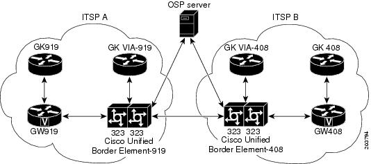
Figure 1 shows a sample topology that uses the Cisco Unified Border Element feature with OSP. With the exception of the authentication and accounting messages that are exchanged between the Cisco Unified Border Element and the OSP server, the exchange of messages between the gateways and gatekeepers is similar to the process illustrated in Figure 4.
Figure 1 Cisco Unified Border Element with OSP Configuration Topology
Note
To configure the Cisco Unified Border Element with OSP, perform the steps in this section.
Prerequisites
•
•
•
SUMMARY STEPS
1.
2.
3.
4.
5.
DETAILED STEPSExamples
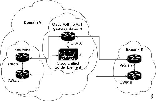
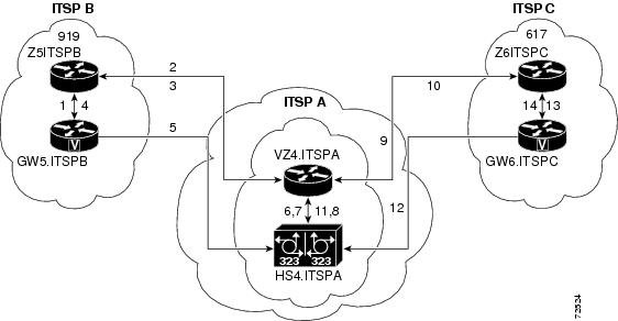
Figure 2 shows two ITSPs using Cisco Unified Border Element and OSP to connect calls passing between the two networks. The examples that follow are based on this illustration.
Figure 2 Cisco Unified Border Element with OSP Feature Topology
Sample Configuration for the Cisco Unified Border Element with OSP Feature
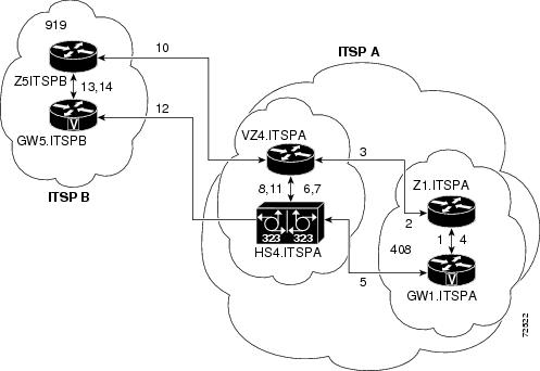
The following example shows the dial peer configuration necessary to complete calls using the configuration shown in Figure 3:
Cisco Unified Border Element-919 Dial Peers
The following dial peer is used for incoming calls from GW919:
dial-peer voice 11 voipapplication sessionincoming called-number 408....session target rascodec transparent!The following dial peer is used for outgoing calls to Cisco Unified Border Element-408:
dial-peer voice 12 voipdestination-pattern 408....session target settlementcodec transparent!The following dial peer is used for incoming calls from Cisco Unified Border Element-408:
dial-peer voice 13 voipapplication sessionincoming called-number 919....session target settlementcodec transparent!The following dial peer is used for outgoing calls to GW919:
dial-peer voice 14 voipdestination-pattern 919....session target rascodec transparent!Cisco Unified Border Element-408 Dial Peers
The following dial peer is used for incoming calls from Cisco Unified Border Element-919:
dial-peer voice 21 voipapplication sessionincoming called-number 408....session target settlementcodec transparent!The following dial peer is used for outgoing calls to GW408:
dial-peer voice 22 voipdestination-pattern 408....session target rascodec transparent!The following dial peer is used for outgoing calls to Cisco Unified Border Element-919:
dial-peer voice 23 voipdestination-pattern 919....session target settlementcodec transparent!The following dial peer is used for incoming calls from GW408:
dial-peer voice 24 voipapplication sessionincoming called-number 919....session target rascodec transparent!Media Statistics on a Cisco Unified Border Element
This chapter describes the media statistics feature. The media statistics command allows you to estimate the values of the packet loss, jitter, and the Round Trip Time (RTT) statistics based on RFC-3550.
To enable media statistics on an Cisco Unified Border Element, perform the steps in this section. This section contains the following subsections:
•
•
•
Restrictions
•
•
•
•
Information About Media Statistics in an Cisco Unified Border Element
The Voip RTP library estimates the values based on RTCP packets received on the Cisco Unified Border Element. This feature adds the capability to generate the media statistics in Cisco Unified Border Element and estimate the values of packet loss, jitter, and Round Trip Time (RTT)
Packet Loss
Packet loss is estimated on Cisco Unified Border Element based on RFC 3550. Packet loss calculation is done based on RTP stream and the computation is done in VOIPRTP library by checking the sequence Number.
•
•
Jitter
Packet jitter is defined as an estimate of the statistical variance of the RTP data packet interarrival time, measured in timestamp units. Jitter is estimated on Cisco Unified Border Elements based on RFC 3550. Jitter is computed in VOIPRTP library.
•
Round Trip Time
The Round Trip Time (RTT) value computed is filled in variable cvVoIPCallActiveRoundTripDelay in CISCO-VOICE-DIAL-CONTROL-MIB.
•
Note
Configuring Media Statistics in a Cisco Unified Border Element
The media statistics feature can be configured in global, or dial peer configuration mode, perform the steps in this section. This section contains the following subsections:
•
•
•
•
Note
•
Configuring Media Statistics in Voice-Service Configuration Mode
To globally enable media statistics in voice-service configuration mode to estimate the values for packet loss, jitter, and RTT, perform the steps in this section.
SUMMARY STEPS
1.
2.
3.
4.
5.
DETAILED STEPSConfiguring Media Statistics on Dial Peer Configuration Mode
To enable media statistics in on a dial peer voice-service configuration mode to estimate the values for packet loss, jitter, and RTT, perform the steps in this section.
SUMMARY STEPS
1.
2.
3.
4.
5.
DETAILED STEPSMonitoring Media Statistics in a Cisco Unified Border Element
Monitor the media statistics with the show call active voice look for following variables:
•
•
•
SUMMARY STEPS1.
2.
3.
4.
5.
6.
7.
DETAILED STEPS
Step 1
Use this command to display media statistics information and indicate whether the media statistic feature is enabled.
c3745-ipipgw#show call active voiceTelephony call-legs: 0SIP call-legs: 2H323 call-legs: 0Call agent controlled call-legs: 0SCCP call-legs: 0Multicast call-legs: 0Total call-legs: 2GENERIC:SetupTime=525050 msIndex=1PeerAddress=6662PeerSubAddress=PeerId=0PeerIfIndex=54LogicalIfIndex=0ConnectTime=527550 msCallDuration=00:00:04 secCallState=4CallOrigin=2ChargedUnits=0InfoType=speechTransmitPackets=112TransmitBytes=2240ReceivePackets=318ReceiveBytes=6360VOIP:ConnectionId[0xA6008E71 0xA8FE11D6 0x800B000D 0x2970B190]IncomingConnectionId[0xA6008E71 0xA8FE11D6 0x800B000D 0x2970B190]CallID=5RemoteIPAddress=1.3.7.16RemoteUDPPort=19512RemoteSignallingIPAddress=1.3.7.16RemoteSignallingPort=52111RemoteMediaIPAddress=1.3.7.16RemoteMediaPort=19512RoundTripDelay=0 msSelectedQoS=best-efforttx_DtmfRelay=rtp-nteFastConnect=FALSEAnnexE=FALSESeparate H245 Connection=FALSEH245 Tunneling=FALSESessionProtocol=sipv2ProtocolCallId=A601C6C1-A8FE11D6-8029B65F-D48EEF95@1.3.7.16SessionTarget=1.3.7.16OnTimeRvPlayout=0GapFillWithSilence=0 msGapFillWithPrediction=0 msGapFillWithInterpolation=0 msGapFillWithRedundancy=0 msHiWaterPlayoutDelay=0 msLoWaterPlayoutDelay=0 msTxPakNumber=0TxSignalPak=0TxComfortNoisePak=0TxDuration=0TxVoiceDuration=0RxPakNumber=0RxSignalPak=0RxComfortNoisePak=0RxDuration=0RxVoiceDuration=0RxOutOfSeq=0RxLatePak=0RxEarlyPak=0RxBadProtocol=0PlayDelayCurrent=0PlayDelayMin=0PlayDelayMax=0PlayDelayClockOffset=0PlayDelayJitter=0PlayErrPredictive=0PlayErrInterpolative=0PlayErrSilence=0PlayErrBufferOverFlow=0PlayErrRetroactive=0PlayErrTalkspurt=0OutSignalLevel=0InSignalLevel=0LevelTxPowerMean=0LevelRxPowerMean=0LevelBgNoise=0ERLLevel=0ACOMLevel=0ErrRxDrop=0ErrTxDrop=0ErrTxControl=0ErrRxControl=0ReceiveDelay=0 msLostPackets=0EarlyPackets=0LatePackets=0SRTP = offTextRelay = offVAD = disabledCoderTypeRate=g729r8CodecBytes=20Media Setting=flow-throughCallerName=CallerIDBlocked=FalseOriginalCallingNumber=6662OriginalCallingOctet=0x0OriginalCalledNumber=6661OriginalCalledOctet=0x0OriginalRedirectCalledNumber=OriginalRedirectCalledOctet=0x80TranslatedCallingNumber=6662TranslatedCallingOctet=0x0TranslatedCalledNumber=6661TranslatedCalledOctet=0x0TranslatedRedirectCalledNumber=TranslatedRedirectCalledOctet=0x80GwReceivedCalledNumber=6661GwReceivedCalledOctet3=0x0GwReceivedCallingNumber=6662GwReceivedCallingOctet3=0x0GwReceivedCallingOctet3a=0x80MediaInactiveDetected=noMediaInactiveTimestamp=MediaControlReceived=LongDurationCallDetected=noLongDurCallTimestamp=LongDurcallDuration=Username=6662GENERIC:SetupTime=525050 msIndex=2PeerAddress=6661PeerSubAddress=PeerId=6661PeerIfIndex=54LogicalIfIndex=0ConnectTime=527550 msCallDuration=00:00:06 secCallState=4CallOrigin=1ChargedUnits=0InfoType=speechTransmitPackets=432TransmitBytes=8640ReceivePackets=112ReceiveBytes=2240VOIP:ConnectionId[0xA6008E71 0xA8FE11D6 0x800B000D 0x2970B190]IncomingConnectionId[0xA6008E71 0xA8FE11D6 0x800B000D 0x2970B190]CallID=6RemoteIPAddress=1.3.7.112RemoteUDPPort=18958RemoteSignallingIPAddress=1.3.7.112RemoteSignallingPort=5060RemoteMediaIPAddress=1.3.7.112RemoteMediaPort=18958RoundTripDelay=0 msSelectedQoS=best-efforttx_DtmfRelay=rtp-nteFastConnect=FALSEAnnexE=FALSESeparate H245 Connection=FALSEH245 Tunneling=FALSESessionProtocol=sipv2ProtocolCallId=D0445D00-62B611D6-800DB698-E7A6FDDD@1.3.7.9SessionTarget=1.3.7.112OnTimeRvPlayout=0GapFillWithSilence=0 msGapFillWithPrediction=0 msGapFillWithInterpolation=0 msGapFillWithRedundancy=0 msHiWaterPlayoutDelay=0 msLoWaterPlayoutDelay=0 msTxPakNumber=0TxSignalPak=0TxComfortNoisePak=0TxDuration=0TxVoiceDuration=0RxPakNumber=0RxSignalPak=0RxComfortNoisePak=0RxDuration=0RxVoiceDuration=0RxOutOfSeq=0RxLatePak=0RxEarlyPak=0RxBadProtocol=0PlayDelayCurrent=0PlayDelayMin=0PlayDelayMax=0PlayDelayClockOffset=0PlayDelayJitter=0PlayErrPredictive=0PlayErrInterpolative=0PlayErrSilence=0PlayErrBufferOverFlow=0PlayErrRetroactive=0PlayErrTalkspurt=0OutSignalLevel=0InSignalLevel=0LevelTxPowerMean=0LevelRxPowerMean=0LevelBgNoise=0ERLLevel=0ACOMLevel=0ErrRxDrop=0ErrTxDrop=0ErrTxControl=0ErrRxControl=0ReceiveDelay=0 msLostPackets=0EarlyPackets=0LatePackets=0SRTP = offTextRelay = offVAD = disabledCoderTypeRate=g729r8CodecBytes=20Media Setting=flow-throughCallerName=CallerIDBlocked=FalseOriginalCallingNumber=6662OriginalCallingOctet=0x0OriginalCalledNumber=6661OriginalCalledOctet=0x0OriginalRedirectCalledNumber=OriginalRedirectCalledOctet=0x80TranslatedCallingNumber=6662TranslatedCallingOctet=0x0TranslatedCalledNumber=6661TranslatedCalledOctet=0x0TranslatedRedirectCalledNumber=TranslatedRedirectCalledOctet=0x80GwReceivedCalledNumber=6661GwReceivedCalledOctet3=0x0GwOutpulsedCalledNumber=6661GwOutpulsedCalledOctet3=0x0GwReceivedCallingNumber=6662GwReceivedCallingOctet3=0x0GwReceivedCallingOctet3a=0x80GwOutpulsedCallingNumber=6662GwOutpulsedCallingOctet3=0x0GwOutpulsedCallingOctet3a=0x80MediaInactiveDetected=noMediaInactiveTimestamp=MediaControlReceived=LongDurationCallDetected=noLongDurCallTimestamp=LongDurcallDuration=Username=6662Telephony call-legs: 0SIP call-legs: 2H323 call-legs: 0Call agent controlled call-legs: 0SCCP call-legs: 0Multicast call-legs: 0Total call-legs: 2Step 2
LostPackets=0LostPackets=126Step 3
RoundTripDelay=0 msRoundTripDelay=4 msStep 4
PlayDelayJitter=0PlayDelayJitter=24Step 5
VoIP RTP active connections :No. CallId dstCallId LocalRTP RmtRTP LocalIP RemoteIP1 5 6 17892 17794 15.5.34.5 15.5.34.1582 6 5 16990 18744 15.5.34.5 15.5.34.6Found 2 active RTP connectionsVoice Quality Enhancements on Cisco Unified Border Element
To configure voice quality enhancements on the Cisco UBE, perform the steps in this section. This section contains the following subsections:
•
•
•
Codec Repacketization
Codec repacketization is used to connect dissimilar networks that have different packetization time periods. A portion of a network might be set to generate packets on the Real-Time Transport Protocol (RTP) voice stream every 10 ms, while another portion may have a packetization period of 20 ms. When one side can adjust to the other's packetization, the call is completed successfully. However, if both sides cannot agree on a common packetization, the call may fail. The codec repacketization enhancement prevents this call failure scenario.
By enabling the Cisco UBE gateway to do codec repacketization, one side of the call can be one packetization period, while allowing the other side can be another. Behavior is predictable, and you can always connect different portions of the voice network.
Note
Because repacketization uses digital signal processor (DSP) transcoding, there is a potential performance impact on DSP and Cisco IOS software. Therefore, codec repacketization should be used only when necessary. To explain the circumstances of when repacketization is and is not necessary, the following scenarios are provided (using G.711 codec as the example):
•
In this case, repacketization will occur because there are codec byte mismatches between endpoints and both endpoints are configured with the fixed-bytes option of the codec command.
•
In this case, repacketization does not occur because neither endpoint is configured with the fixed-bytes option of the codec command. The current CLI codec byte negotiation is used.
•
In this case, the fixed-bytes option of the codec command is configured at both endpoints, but Cisco IOS software detects that repacketization is not needed. No repacketization is performed.
•
Endpoint 1 uses fixed codec byte size 160 and Endpoint 2 likes to use codec byte size 240. In this case, repacketization occurs because of the fixed-bytes option configured on Endpoint-1.
Prerequisites
•
Restrictions
•
•
•
•
Configuring Codec Repacketization
To configure codec repacketization on a voice gateway, you must configure codec byte size with different values for the incoming and outgoing Voice over IP (VoIP) dial peers.
•
•
•
Configuring Codec Repacketization the Incoming VoIP Dial Peer
To configure the incoming VoIP dial peer, complete the following task:
SUMMARY STEPS
1.
2.
3.
4.
5.
DETAILED STEPS
Step 1
enable
Example:Router> enable
Enables privileged EXEC mode.
•
Step 2
configure terminal
Example:Router# configure terminal
Enters global configuration mode.
Step 3
dial-peer voice voip
Example:Router(config)# dial-peer voice voip
Enters dial-peer configuration mode, and specifies VoIP as the method of voice encapsulation.
Step 4
incoming called-number number
Example:Router(config-dialpeer)# incoming called-number 12345
Specifies a digit string that can be matched by an incoming call to associate the call with the dial peer.
•
Step 5
codec codec-type bytes payload-size fixed-bytes
Example:Router(config-dialpeer)# codec g711ulaw bytes 160 fixed-bytes
Specifies the voice coder rate of speech for a dial peer, the number of bytes in the voice payload of each frame, and indicates that the codec byte size is fixed and non-negotiable.
Configuring Codec Repacketization the Outgoing VoIP Dial Peer
To configure the outgoing VoIP dial peer, complete the following task:
SUMMARY STEPS
1.
2.
3.
4.
5.
6.
DETAILED STEPS
Step 1
enable
Example:Router> enable
Enables privileged EXEC mode.
•
Step 2
configure terminal
Example:Router# configure terminal
Enters global configuration mode.
Step 3
dial-peer voice tag voip
Example:Router(config)# dial-peer voice 123 voip
Enters dial-peer configuration mode, defines a particular dial peer, and specifies the method of voice encapsulation as VoIP.
•
Step 4
destination-pattern string
Example:Router(config)# destination-pattern 12345
Specifies either the prefix or the full E.164 telephone number to be used for a dial peer.
•
Step 5
session target ipv4:destination-address
Example:Router(config-dialpeer)# session target ipv4:10.1.1.1
Designates a network-specific address to receive calls from a VoIP dial peer.
•
Step 6
codec codec-type
Example:Router(config-dialpeer)# codec g711ulaw
Specifies the voice coder rate of speech for a dial peer.
Table 3 shows some commonly used mappings from codec bytes to codec ms packets.
Table 3 Packet Bytes and Packet Time Conversion for Codecs Supported in Repacketization (Transrating) Function
g711ulaw, g711alaw
80 bytes
160 bytes
240 bytes
64,000 bps; PB = PT x 8
g729abr8, g729ar8, g729br8, g729r81
10 bytes
20 bytes
30 bytes
8,000 bps; PB = PT
g722-64
80 bytes
160 bytes
240 bytes
64,000 bps; PB = PT x 8
g723r632
-
-
24 bytes
6,300 bps; PB = PT/30 x 24
Note: For PT = 60 ms, PB = 48 bytesg723r533
-
-
20 bytes
5,300 bps; PB = PT/30 x 20
Note: For PT = 60 ms, PB = 40 bytes
1 The supported packetization period for G.729r8 is limited to a maximum of 60 ms or payload size of 60 bytes.
2 The supported packetization period for G.723r63 is limited to a maximum of 60 ms or payload size of 48 bytes.
3 The supported packetization period for G.723r53 is limited to a maximum of 60 ms or payload size of 40 bytes.
Verifying Codec Repacketization
To verify that codec repacketization is turned on and working properly, use the following show commands:
Step 1
Router# show voip rtp connectionsVoIP RTP active connections :No. CallId dstCallId LocalRTP RmtRTP LocalIP RemoteIP1 37 38 16582 18236 10.1.1.2 10.1.1.72 38 37 16524 19542 10.1.1.2 10.1.1.13 39 40 17644 2000 10.1.1.2 10.1.1.24 41 40 16622 2000 10.1.1.2 10.1.1.2Step 2
Router# show sccp connectionssess_id conn_id stype mode codec ripaddr rport sport3 4 xcode sendrecv g711u 100.1.1.2 2000 166223 3 xcode sendrecv g711u 100.1.1.2 2000 17644Total number of active session(s) 1, and connection(s) 2
Configuring IP-to-IP Call Gain/Loss Control
This feature enables the adjustment of the audio volume within a Cisco UBE call. As with codec repacketization, dissimilar networks that have different built-in loss/gain characteristics may experience connectivity problems. By adding the ability to control the loss/gain within the Cisco UBE, you can more easily connect your networks.
Caution
To configure IP-IP Call Gain/Loss Control on a voice gateway, you must configure the incoming and outgoing VoIP dial peers, perform the steps in this section. This section contains the following subsections:
•
•
•
Configuring IP-to-IP Call Gain/Loss Control on the Incoming VoIP Dial Peer
To configure the incoming VoIP dial peer, complete the following task:
SUMMARY STEPS
1.
2.
3.
4.
5.
6.
7.
DETAILED STEPS
Step 1
enable
Example:Router> enable
Enables privileged EXEC mode.
•
Step 2
configure terminal
Example:Router# configure terminal
Enters global configuration mode.
Step 3
dial-peer voice tag voip
Example:Router(config)# dial-peer voice 123 voip
Enters dial-peer configuration mode, defines a particular dial peer, and specifies the method of voice encapsulation as VoIP.
•
Step 4
incoming called-number number
Example:Router(config-dialpeer)# incoming called-number 12345
Specifies a digit string that can be matched by an incoming call to associate the call with the dial peer.
•
Step 5
codec codec-type
Example:Router(config-dialpeer)# codec g711ulaw
Specifies the voice coder rate of speech for a dial peer.
•
Step 6
audio incoming level-adjustment value
Example:Router(config-dialpeer)# audio incoming level-adjustment
Enables the incoming IP-IP call gain/loss feature on either the incoming dial peer or the outgoing dial peer.
•
Step 7
audio outgoing level-adjustment value
Example:Router(config-dialpeer)# audio outgoing level-adjustment
Enables the outgoing IP-IP call gain/loss feature on either the incoming dial peer or the outgoing dial peer.
•
Configuring IP-to-IP Call Gain/Loss Control on the Outgoing VoIP Dial Peer
To configure the outgoing VoIP dial peer, complete the following task:
SUMMARY STEPS
1.
2.
3.
4.
5.
6.
7.
8.
DETAILED STEPS
Step 1
enable
Example:Router> enable
Enables privileged EXEC mode.
•
Step 2
configure terminal
Example:Router# configure terminal
Enters global configuration mode.
Step 3
dial-peer voice tag voip
Example:Router(config)# dial-peer voice 123 voip
Enters dial-peer configuration mode, defines a particular dial peer, and specifies the method of voice encapsulation as VoIP.
•
Step 4
destination-pattern string
Example:Router(config-dialpeer)# destination-pattern 12345
Specifies either the prefix or the full E.164 telephone number to be used for a dial peer.
•
Step 5
session target ipv4:destination-address
Example:Router(config-dialpeer)# session target ipv4:10.1.1.1
Designates a network-specific address to receive calls from a VoIP dial peer.
•
Step 6
codec codec-type
Example:Router(config-dialpeer)# codec g711ulaw
Specifies the voice coder rate of speech for a dial peer.
Step 7
audio incoming level-adjustment value
Example:Router(config-dialpeer)# audio incoming level-adjustment 5
Enables the incoming IP-IP call gain/loss feature on either the incoming dial peer or the outgoing dial peer.
•
Step 8
audio outgoing level-adjustment value
Example:Router(config-dialpeer)# audio outgoing level-adjustment -5
Enables the outgoing IP-IP call gain/loss feature on either the incoming dial peer or the outgoing dial peer.
•
Note
Verifying IP-IP Call Gain/Loss
To verify that IP-IP call gain/loss is turned on and working properly, use the following show commands:
Step 1
Router# show call activeStep 2
Router# show call historyConfiguring Voice Quality Metrics
This feature adds voice quality measurements for the Cisco UBE voice call. Prior to this feature, the ability to gather statistics within the gateway required a TDM-to-IP call because the DSP performed statistics gathering. The Voice Quality Metrics feature enables statistics gathering on packet arrival (late/lost/early). From these statistics, a voice quality measurement is developed to give the quality of the call. The output is in a simple format, using a system of good, poor, and bad types of ratings.
The Voice Quality Metrics feature is enabled by the addition of the media monitoring [max-calls] command:
•
•
•
Note
SUMMARY STEPS
1.
2.
3.
4.
5.
6.
7.
8.
DETAILED STEPS
Step 1
enable
Example:Router> enable
Enables privileged EXEC mode.
•
Step 2
configure terminal
Example:Router# configure terminal
Enters global configuration mode.
Step 3
voice service voip
Example:Router(config)# voice service voip
Enters voice-service configuration mode and specifies Voice over IP as the voice-encapsulation type.
Step 4
mode border-element
Example:Router(conf-voi-serv)# mode border-element
Enables the audio call-scoring of the media monitoring command. If you do not enter the mode border-element command, the media monitoring command is not available for Cisco UBE voice connections.
Note
Step 5
media monitoring [max-calls]
Example:Router(conf-voi-serv)# media monitoring 300
Enables media monitoring and specifies the maximum number of calls to be monitored.
•
Step 6
end
Example:Router(conf-voi-serv)# end
•
Step 7
dial-peer voice tag voip
Example:Router(config)# dial-peer voice 123 voip
Enters dial-peer configuration mode, defines a particular dial peer, and specifies the method of voice encapsulation as VoIP.
•
Step 8
media monitoring
Example:Router(config-dialpeer)# media monitoring
Enables media monitoring for calls landing on the dial peer specified in Step 7.
Verifying Voice Quality Metrics
To verify that the voice quality metrics feature is turned on and working properly, use the following show commands:
•
•
•
Step 1
Router# show voice monitoring-channelsmax vq mon channels = 10 vq mon channels in use = 2 vq mon channels left =8Step 2
Router# show call active voiceRxPakNumber=5496 RxSignalPak=0 RxComfortNoisePak=0 RxDuration=109900 RxVoiceDuration=109920 RxOutOfSeq=0 RxLatePak=0 RxEarlyPak=0 RxBadProtocol=0 LevelRxPowerMean=0 ErrRxDrop=0 ErrRxControl=0Step 3
Router# show call active voice statsDSP/CS: CR=0.0527, AV=0.0502, MX=0.0527, CT=1220, TT=24270, OK=50, CS=44, SC=0, TS=50, DC=0SP/RF: ML=3.9855, MC=0.0000, R1=79, R2=0, IF=15, ID=0, IE=0, BL=25, R0=94, VR=1.1In the sample output, the following can be noted:
•
•
•
•
•
Table 4 defines the abbreviations used in the sample output.
SRST Support for G.722 Codec
SRST provides fail-over support for IP phones at remote branch offices that are supported by a central Cisco Unified Communications Manager system with the phones running the SCCP/SIP protocol across WAN links.
Phones are provisioned by Cisco Unified Communications Manager. This information is stored in the phones and then made available to the SRST router when the WAN link fails. SRST extracts the stored information from the phones when they register for service with SRST. SRST uses this information to automatically build the needed configuration.
Prior to Cisco IOS Release 15.0(1)M, G.711 ulaw has been the default narrowband codec for LAN. As the use of wideband codecs expands, G.722 is expected to be the default wideband codec. This increased use of the G.722 codec in LANs has created a need for SRST support with this codec.
This feature provides support for the G.722 codec in SRST mode. To enable G.722-64K codec support as the default codec in SRST mode, enter the codec g722-64k command in call-manager-fallback configuration mode:
Router(config)# call-manager-fallbackRouter(config-cm-fallback)# codec g722-64kThe following shows a sample configuration of call-manager-fallback with the G.722 codec configured:
Router# call-manager-fallback
max-conferences 8 gain -6
transfer-system full-consult
codec g722-64
incoming called-number 52222Troubleshooting and Verifying Fundamental Cisco Unified Border Element Configuration and Operation
To troubleshoot or verify connections in an Cisco Unified Border Element, perform the steps in this section. This section contains the following subsections:
•
Troubleshooting Tips
Caution
•
•
•
•
•
Router# debug voip rtcp sub-rtcpVOIP RTCP Subrtcp debugging is onOct 16 19:35:26.870: SUBRTCP:tx SR (15.5.34.5-17893)->(15.5.34.158,17795) rtcp-intv(5002 ms)Oct 16 19:35:26.870: SUBRTCP Sender Report dump Length - 32:80 FA 00 07 0F 25 22 05 80 C8 00 05 C8 DE 5D 7E DE C6 2A 6D 00 00 00 00 00 00 00 00 00 00 00 00Oct 16 19:35:26.878: SUBRTCP:tx SR (15.5.34.5-16991)->(15.5.34.6,18745) rtcp-intv(5005 ms)Oct 16 19:35:26.878: SUBRTCP Sender Report dump Length - 32:80 FA 00 07 05 CD 22 05 80 C8 00 05 C8 DE 5D 7E E0 D2 59 C1 00 00 00 00 00 00 00 00 00 00 00 00•
Router# debug voip rtp statisticsVOIP RTP Statistics debugging is onOct 16 19:38:20.000: RTP[15.5.34.6-0x1B5B2298]: loss(0) jitter(5 ms, 5992 us)Oct 16 19:38:22.556: RTP[15.5.34.6-0x1B5B2298]: loss(0) jitter(8 ms, 8054 us)For additional examples of show and debug command output and details on interpreting the output, see the following resources:
•
•
•
Verifying Fundamental Cisco Unified Border Element Configurations
To verify Cisco Unified Border Element feature configuration and operation, perform the following steps (listed alphabetically) as appropriate.
Note
SUMMARY STEPS
1.
2.
3.
4.
5.
6.
7.
8.
9.
DETAILED STEPS
Step 1
Use this command to display the active video H.323 call legs.
Step 2
Use this command to display call information for voice calls that are in progress.
Step 3
Use this command to display the fax transmissions that are in progress.
Step 4
Use this command to display the history of video H.323 call legs.
Step 5
Use this command to display the history of voice call legs.
Step 6
Use this command to display the call history table for fax transmissions that are in progress.
Step 7
Use this command to display the carrier ID list or IP circuit utilization.
Step 8
Use this command to display information about voice dial peers.
Step 9
Use this command to verify which H.323-to-H.323, H.323-to-SIP, or SIP-to-SIP connection types are supported.
Step 10
Use this command to display active Real-Time Transport Protocol (RTP) connections.
Configuration Examples for Fundamental Cisco Unified Border Element
This chapter includes the following configuration examples:
•
•
•
•
•
•
•
Cisco Unified Border Element: Example
Figure 3 shows an example configuration of the Cisco Unified Border Element feature.
Figure 3 Cisco Unified Border Element Feature Topology
For a detailed description of the actions that occur during a call, see Figure 1 The following examples show gateway and gatekeeper configuration.
Originating Gateway Configuration: Example
interface Ethernet0/0ip address 10.16.8.132 255.255.255.0half-duplexh323-gateway voip interfaceh323-gateway voip id GK408 ipaddr 10.16.8.123 1718h323-gateway voip h323-id GW408!dial-peer voice 919 voipdestination-pattern 919.......session target ras!gatewayOriginating Gatekeeper Configuration: Example
gatekeeperzone local GK408 usa 10.16.8.123zone remote GKVIA usa 10.16.8.24 1719zone prefix GKVIA 919*gw-type-prefix 1#*no shutdownCisco Unified Border Element Configuration: Example
!voice service voipno allow-connections any to potsno allow-connections pots to anyallow-connections h323 to h323h323ip circuit max-calls 1000ip circuit default only!!interface FastEthernet0/0ip address 10.16.8.145 255.255.255.0ip route-cache same-interfaceduplex autospeed autoh323-gateway voip interfaceh323-gateway voip id GKVIA ipaddr 10.16.8.24 1718h323-gateway voip h323-id IPIPGWh323-gateway voip tech-prefix 1#!!dial-peer voice 919 voipincoming called-number 919.......destination-pattern 919.......session target rascodec transparent!gatewayVia Zone Gatekeeper Configuration: Example
gatekeeperzone local GKVIA usa 10.16.8.24zone remote GK919 usa 10.16.8.146 1719 invia GKVIA outvia GKVIAzone prefix GK919 919*no shutdownTerminating Gateway: Example
interface Ethernet0/0ip address 10.16.8.134 255.255.255.0half-duplexh323-gateway voip interfaceh323-gateway voip id GK919 ipaddr 10.16.8.146 1718h323-gateway voip h323-id GW919h323-gateway voip tech-prefix 919!dial-peer voice 919 potsdestination-pattern 919.......port 1/0:1!gatewayTerminating Gatekeeper Configuration: Example
gatekeeperzone local GK919 usa 10.16.8.146gw-type-prefix 1#* default-technologyno shutdownLocal-to-Remote Network Using the Cisco Unified Border Element: Example
Figure 4 shows a local-to-remote network using the Cisco Unified Border Element feature.
Figure 4 Local-to-Remote Network Using the Cisco Unified Border Element Feature Topology
Note
example09186a00801b0803.shtml
Remote-to-Local Network Using the Cisco Unified Border Element: Example
Figure 5 shows a remote-to-local network using the Cisco Unified Border Element feature.
Figure 5 Remote-to-Local Network Using the Cisco Unified Border Element Feature Topology
Note
09186a0080203edc.shtml.
Remote-to-Remote Network Using a Cisco Unified Border Element: Example
Figure 6 shows a remote-to-remote network using an Cisco Unified Border Element.
Figure 6 Remote-to-Remote Network Using a Cisco Unified Border Element Topology
Note
09186a0080203edd.shtml.
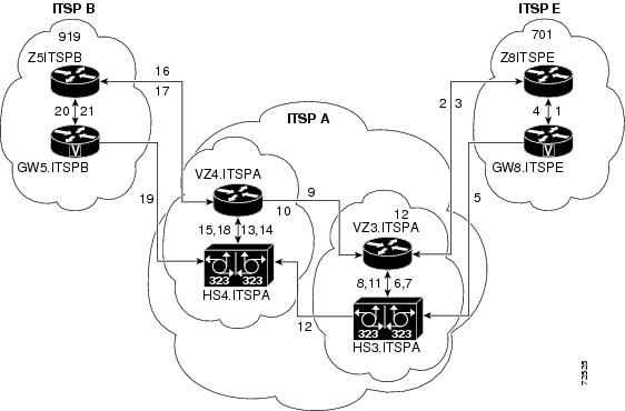
Remote-to-Remote Network Using Two Cisco Unified Border Elements: Example
Figure 7 shows a remote-to-remote network using two Cisco Unified Border Elements.
Figure 7 Remote-to-Remote Network Using Two Cisco Unified Border Elements Topology
Note
09186a0080203edb.shtml.Using the Cisco Unified Border Element to Assign DSCP Code Points to Gateway Traffic
The following example configures the Cisco Unified Border Element to assign DSCP code points to traffic that passes through the gateway:
dial-peer voice 1 voipincoming called-number .Tdestination-pattern .Tip qos dscp ef mediaip cos dscp af31 signalingsession target rascodec transparentUsing Class and Policy Maps to Control Bandwidth Allocation
The following example uses class and policy maps to control bandwidth allocation based on matching received DSCP code points:
class-map match-all Silver-Datamatch ip dscp af11match ip dscp af12match ip dscp af13class-map match-all Voice-Controlmatch ip dscp af31class-map match-all Gold-Datamatch ip dscp af21match ip dscp af22match ip dscp af23class-map match-all Voicematch ip dscp ef!!policy-map LLQclass Voicepriority percent 40class Voice-Controlbandwidth remaining percent 5class Gold-Databandwidth remaining percent 45class Silver-Databandwidth remaining percent 35class class-defaultbandwidth remaining percent 5random-detect dscp-basedrandom-detect dscp 2 70 128 10random-detect dscp 4 58 128 10random-detect dscp 6 44 128 10policy-map FairQueueclass class-defaultCodec Repacketization: Example
The following is a sample configuration of codec repacketization for a destinated callee number 52222:
dial-peer voice 416 voipdestination-pattern 52222session protocol sipv2session target ipv4:1.7.92.99codec g711ulaw bytes 160 fixed-bytes!dial-peer voice 4161 voipincoming called-number 52222session protocol sipv2codec g711ulaw bytes 80 fixed-bytesVoice Quality Metrics: Example
The following is a sample configuration of the voice quality metrics feature on a gateway that allows a maximum of 100 calls to be monitored, and calls under voip dial-peer 4161 to be monitored:
voice service voipmedia monitor 100allow-connections h323 to h323allow-connections h323 to sipallow-connections sip to h323allow-connections sip to sipdial-peer voice 4161 voipmedia monitoringWhere to Go Next
•
•
•
•
Additional References
The following sections provide additional references related to the Cisco UBE Configuration Guide.
Note
•
•
Related Documents
Standards
H.323 Version 4 and earlier
H.323 (ITU-T VOIP protocols)
H.323 - H.245 Version 12, Annex R
H.323 (ITU-T VOIP protocols)
MIBs
RFCs
Technical Assistance
Feature Information for Cisco Unified Border Element Configuration Guide
Table 5 lists the features in this module and provides links to specific configuration information. Only features that were introduced or modified in Cisco IOS Release 12.3(1) or a later release appear in the table.
For information on a feature in this technology that is not documented here, see the "Cisco Unified Border Element Features Roadmap."
Note
Glossary
DSP—Digital Signal Processor
ETSI—European Telecommunications Standards Institute
GSM—Groupe Speciale Mobile
RTP—Real-Time Transport Protocol
SCCP—Skinny Client Control Protocol
SIP—Session Initiation Protocol
SRTP—Secure Real-Time Transport Protocol
VoIP—Voice over Internet Protocol
TDM—Time Division Multiplexing
3GPP—Third Generation Partnership Project
3G—Third generation
Note
CCDE, CCENT, CCSI, Cisco Eos, Cisco Explorer, Cisco HealthPresence, Cisco IronPort, the Cisco logo, Cisco Nurse Connect, Cisco Pulse, Cisco SensorBase, Cisco StackPower, Cisco StadiumVision, Cisco TelePresence, Cisco TrustSec, Cisco Unified Computing System, Cisco WebEx, DCE, Flip Channels, Flip for Good, Flip Mino, Flipshare (Design), Flip Ultra, Flip Video, Flip Video (Design), Instant Broadband, and Welcome to the Human Network are trademarks; Changing the Way We Work, Live, Play, and Learn, Cisco Capital, Cisco Capital (Design), Cisco:Financed (Stylized), Cisco Store, Flip Gift Card, and One Million Acts of Green are service marks; and Access Registrar, Aironet, AllTouch, AsyncOS, Bringing the Meeting To You, Catalyst, CCDA, CCDP, CCIE, CCIP, CCNA, CCNP, CCSP, CCVP, Cisco, the Cisco Certified Internetwork Expert logo, Cisco IOS, Cisco Lumin, Cisco Nexus, Cisco Press, Cisco Systems, Cisco Systems Capital, the Cisco Systems logo, Cisco Unity, Collaboration Without Limitation, Continuum, EtherFast, EtherSwitch, Event Center, Explorer, Follow Me Browsing, GainMaker, iLYNX, IOS, iPhone, IronPort, the IronPort logo, Laser Link, LightStream, Linksys, MeetingPlace, MeetingPlace Chime Sound, MGX, Networkers, Networking Academy, PCNow, PIX, PowerKEY, PowerPanels, PowerTV, PowerTV (Design), PowerVu, Prisma, ProConnect, ROSA, SenderBase, SMARTnet, Spectrum Expert, StackWise, WebEx, and the WebEx logo are registered trademarks of Cisco and/or its affiliates in the United States and certain other countries.
All other trademarks mentioned in this document or website are the property of their respective owners. The use of the word partner does not imply a partnership relationship between Cisco and any other company. (1002R)
Any Internet Protocol (IP) addresses used in this document are not intended to be actual addresses. Any examples, command display output, and figures included in the document are shown for illustrative purposes only. Any use of actual IP addresses in illustrative content is unintentional and coincidental.
© 2010 Cisco Systems, Inc. All rights reserved.