Downloads |
 Feedback Feedback
|
Table Of Contents
Prerequisites for Remote Access MPLS-VPNs
Restrictions for Remote Access MPLS-VPNs
Information About Remote Access MPLS-VPNs
Introduction to Remote Access MPLS-VPNs
How to Configure Remote Access MPLS-VPNs
Configuring a Virtual Template Interface
Configuring PPPoE in a Broadband Aggregation Group
Configuration Examples for Remote Access MPLS-VPNs
Configuring Remote Access MPLS-VPNs with One VRF for PPPoE Sessions: Example
Feature Information for Remote Access MPLS-VPNs
Remote Access MPLS-VPNs
First Published: August 12, 2002Last Updated: November 21, 2008The Remote Access MPLS-VPNs feature allows the service provider to offer a scalable end-to-end Virtual Private Network (VPN) service to remote users. This feature integrates the Multiprotocol Label Switching (MPLS)-enabled backbone with broadband access capabilities.
Finding Feature Information
Your software release may not support all the features documented in this module. For the latest feature information and caveats, see the release notes for your platform and software release. To find information about the features documented in this module, and to see a list of the releases in which each feature is supported, see the "Feature Information for Remote Access MPLS-VPNs" section.
Use Cisco Feature Navigator to find information about platform support and Cisco IOS and Catalyst OS software image support. To access Cisco Feature Navigator, go to http://www.cisco.com/go/cfn. An account on Cisco.com is not required.
Contents
•
Prerequisites for Remote Access MPLS-VPNs
•
•
•
•
•
Prerequisites for Remote Access MPLS-VPNs
•
–
–
–
–
•
•
Restrictions for Remote Access MPLS-VPNs
•
Information About Remote Access MPLS-VPNs
Before configuring Remote Access MPLS-VPNs, you should understand the following concepts:
•
•
Introduction to Remote Access MPLS-VPNs
MPLS-based VPNs allow service providers to deploy a scalable and cost-effective VPN service that provides a stable and secure path through the network. An enterprise connects to geographically dispersed sites in the Internet service provider's (ISPs) network through use of an MPLS backbone. Sites are interconnected to create an MPLS VPN.
The Remote Access MPLS-VPNs feature allows the service provider to offer a scalable end-to-end VPN service to remote users. The Remote Access MPLS-VPNs feature integrates the MPLS-enabled backbone with broadband access capabilities. By integrating access VPNs with MPLS VPNs, a service provider can:
•
•
•
•
•
MPLS VPN Architecture
MPLS VPN architecture enables the service provider to build the MPLS VPN network one time and add VPNs for new customers as needed, including them in the already established network. The elements that comprise the MPLS VPN are:
•
•
•
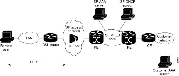
Figure 1 shows an example of MPLS VPN network architecture.
Figure 1 MPLS VPN Network—Example
PPP over Ethernet to MPLS VPN
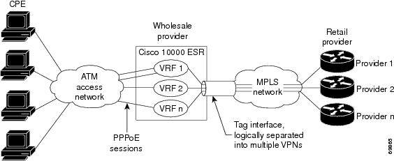
Figure 2 shows the topology of integrated PPP over Ethernet (PPPoE) access to an MPLS VPN.
Figure 2 PPPoE Access to MPLS VPN Topology
In the figure, the service provider operates an MPLS VPN that interconnects all customer sites. The service provider's core network is an MPLS backbone with VPN service capability. The service provider provides all remote access operations to its customer. The network-side interfaces are tagged interfaces, logically separated into multiple VPNs.
Remote access is provided using a PPPoE connection. In this model, when a remote user attempts to establish a connection with a corporate network, a PPPoE session is initiated and is terminated on the service provider's virtual home gateway (VHG) or PE router. All remote hosts connected to a particular CE router must be part of the VPN to which the CE router is connected.
The PPPoE to MPLS VPN architecture is a flexible architecture with the following characteristics:
•
•
•
The following events occur as the VHG or PE router processes the incoming PPPoE session:
1.
2.
3.
–
–
–
Typically, the customer RADIUS server is located within the customer VPN. To ensure that transactions between the VHG/PE router and the customer RADIUS server occur over routes within the customer VPN, the VHG/PE router is assigned at least one IP address that is valid within theVPN.
4.
5.
–
–
–
6.
How to Configure Remote Access MPLS-VPNs
To configure the RA to MPLS VPN feature, perform the following configuration tasks:
•
•
Configuring a Virtual Template Interface
To create and configure a virtual template interface that can be configured and applied dynamically in creating virtual access interfaces, perform the steps in the following task.
SUMMARY STEPS
1.
2.
3.
4.
5.
6.
DETAILED STEPS
Configuring PPPoE in a Broadband Aggregation Group
To configure a broadband aggregation (BBA) group for PPPoE and to link it to the appropriate virtual template interface, perform the steps in the following task.
SUMMARY STEPS
1.
2.
3.
4.
5.
6.
7.
8.
9.
10.
DETAILED STEPS
Configuration Examples for Remote Access MPLS-VPNs
This section provides the following configuration examples:
•
Configuring Remote Access MPLS-VPNs with One VRF for PPPoE Sessions: Example
The following example shows how to configure the RA to MPLS VPN feature with one VRF for PPPoE sessions:
!!Enables the AAA access control model.aaa new-model!!Configures AAA accounting.aaa authentication login default noneaaa authentication enable default noneaaa authentication ppp default group radiusaaa authorization config-commandsaaa authorization network default localaaa session-id commonenable password cisco!username pppoe password 0 pppoeusername common password 0 common!!Creates the common VRF.ip vrf commonrd 100:1000route-target export 100:1000route-target import 100:1000!!Specifies the BBA group to be used to establish PPPoE sessions and specifies the maximum!number of PPPoE sessions to be established over a vlan.bba-group pppoevirtual-template 1sessions per-mac limit 32000!no virtual-template snmp!!Configures the small buffer.buffers small permanent 15000!!Defines the general loopback interface used for reachability to the router and as a!source IP address for sessions (IBGP, TDP, and so on).interface Loopback0ip address 10.16.3.1 255.255.255.255ip ospf network point-to-point !!Creates a loopback interface in the vpn1 VRF. You do this for each customer VRF you IP!unnumber interfaces to.interface Loopback1ip vrf forwarding vpn1ip address 10.24.1.1 255.255.255.255!interface Loopback2ip vrf forwarding vpn2ip address 10.8.1.2 255.255.255.255!interface gigabit ethernet 0/0/0load-interval 30negotiation autono cdp enableinterface gigaethernet 0/0/0.9encapsulation dot1q 9pppoe enableno cdp enable!!Enables label switching of IP packets on the interface.interface GigabitEthernet1/0/0ip address 10.1.10.1 255.255.0.0no ip redirectsload-interval 30negotiation autotag-switching ip!!Defines the virtual template and associates the common VRF with it.interface Virtual-Template1ip vrf forwarding commonip unnumbered Loopback1peer default ip address pool commonppp authentication chap!!Configures OSPF to advertise the networks.router ospf 100log-adjacency-changesauto-cost reference-bandwidth 1000network 10.16.3.1 0.0.0.0 area 0network 10.1.0.0 0.0.255.255 area 0!router ripversion 2!!Enters address family configuration mode to configure the VRF for PE to CE routing!sessions.address-family ipv4 vrf commonversion 2network 10.0.0.0no auto-summaryexit-address-family!!Configures BGP to advertise the networks for the VPN.router bgp 100no synchronizationno bgp default ipv4-unicastbgp log-neighbor-changesneighbor 172.16.1.4 remote-as 100neighbor 172.16.1.4 activate!!Enters address family configuration mode to configure the common VRF for PE to CE routing!sessions.address-family ipv4 vrf commonno auto-summaryno synchronizationaggregate-address 10.10.0.0 255.255.0.0 summary-onlyexit-address-family!address-family vpnv4neighbor 172.16.1.4 activateneighbor 172.16.1.4 send-community bothexit-address-family!!Specifies the IP local pool to use for the VRF address assignment.ip local pool common 10.10.1.1 10.10.126.0ip classless!Enters routing information in the routing table for the VRF.ip route 10.0.0.0 255.0.0.0 FastEthernet0/0/0 10.9.0.1ip route vrf common 10.22.0.0 255.255.0.0 Null0ip route vrf common 10.30.0.0 255.255.0.0 2.1.1.1 3ip route vrf common 10.32.0.0 255.255.0.0 2.2.151.1 2ip route vrf common 10.33.0.0 255.255.0.0 2.3.101.1 2no ip http serverip pim bidir-enable!no cdp run!!Specifies the RADIUS host and configures RADIUS accounting. radius-server retransmit is!on by default and cannot be removed.radius-server host 10.19.100.150 auth-port 1645 acct-port 1646radius-server retransmit 3radius-server key testradius-server authorization permit missing Service-Typeradius-server vsa send authenticationcall admission limit 90!Additional References
The following sections provide references related to the Remote Access MPLS-VPNs feature.
Related Documents
Standards
MIBs
None
To locate and download MIBs for selected platforms, Cisco IOS releases, and feature sets, use Cisco MIB Locator found at the following URL:
RFCs
Technical Assistance
Command Reference
The following commands are introduced or modified in the feature or features documented in this module. For information about these commands, see the Cisco IOS MPLS Command Reference at http://www.cisco.com/en/US/docs/ios/mpls/command/reference/mp_book.html. For information about all Cisco IOS commands, use the Command Lookup Tool at http://tools.cisco.com/Support/CLILookup.
Feature Information for Remote Access MPLS-VPNs
Table 1 lists the release history for this feature.
Not all commands may be available in your Cisco IOS software release. For release information about a specific command, see the command reference documentation.
Use Cisco Feature Navigator to find information about platform support and software image support. Cisco Feature Navigator enables you to determine which Cisco IOS and Catalyst OS software images support a specific software release, feature set, or platform. To access Cisco Feature Navigator, go to http://www.cisco.com/go/cfn. An account on Cisco.com is not required.
Note
Glossary
CE—customer edge.
PPPoE—Point-to-Point Protocol over Ethernet.
PE—provider edge.
Cisco and the Cisco Logo are trademarks of Cisco Systems, Inc. and/or its affiliates in the U.S. and other countries. A listing of Cisco's trademarks can be found at www.cisco.com/go/trademarks. Third party trademarks mentioned are the property of their respective owners. The use of the word partner does not imply a partnership relationship between Cisco and any other company. (1005R)
Any Internet Protocol (IP) addresses used in this document are not intended to be actual addresses. Any examples, command display output, and figures included in the document are shown for illustrative purposes only. Any use of actual IP addresses in illustrative content is unintentional and coincidental.
© 2002-2008 Cisco Systems, Inc. All rights reserved.