-
Cisco CMTS Router Quality of Service Features Configuration Guide, Release 12.2SC
-
Default DOCSIS ToS Overwrite
-
DOCSIS 1.1 for the Cisco CMTS Routers
-
DOCSIS WFQ Scheduler on the Cisco CMTS Routers
-
Dynamic Bandwidth Sharing on the Cisco CMTS Router
-
Fairness Across DOCSIS Interfaces
-
MQC QoS on the Cisco CMTS Routers
-
Service Flow Admission Control for the Cisco CMTS Routers
-
Subscriber Traffic Management for the Cisco CMTS Routers
-
 Feedback
Table Of Contents
DOCSIS 1.1 for the Cisco CMTS Routers
Prerequisites for DOCSIS 1.1 Operations
Restrictions for DOCSIS 1.1 Operations
Baseline Privacy Interface Plus
Packet Header Suppression Rules
Enhanced Rate Bandwidth Allocation (ERBA) Support for DOCSIS 1.0 Cable Modems
DOCSIS 3.0 Downstream Peak Traffic Rate TLV Support for ERBA
Suppressing Upstream and Downstream Peak Rate TLVs for pre DOCSIS 3.0 Cable Modems
How to Configure the Cisco CMTS for DOCSIS 1.1 Operations
Configuring Baseline Privacy Interface
Downloading the DOCSIS Root Certificate to the CMTS
Adding a Manufacturer's Certificate as a Trusted Certificate
Adding a Certificate as a Trusted Certificate Using the Command Line Interface
Adding a Certificate as a Trusted Certificate Using SNMP Commands
Adding a Manufacturer's or CM Certificate to the Hotlist
Adding a Certificate to the Hotlist Using the Command Line Interface
Adding a Certificate to the Hotlist Using SNMP Commands
Configuring Downstream ERBA Settings for DOCSIS 1.0 Cable Modems
Enabling DOCSIS 1.1 Downstream Maximum Transmit Burst on the Cisco uBR10012 Router
Displaying the Status of Cable Modems
Displaying a Summary Report for the Cable Modems
Displaying the Capabilities of the Cable Modems
Displaying Detailed Information About a Particular Cable Modem
Monitoring the RF Network and Cable Interfaces
Displaying Information About Cloned Cable Modems
Denying RF Access For Cable Modems
Displaying Information About the Mac Scheduler
Displaying Information About QoS Parameter Sets
Displaying Information About Service Flows
Displaying Information About Service IDs
Displaying the Current BPI+ State of Cable Modems
Displaying the BPI+ Timer Values on the CMTS
Displaying the Certificate List on the CMTS
Configuration Examples for DOCSIS 1.1 Operations
DOCSIS 1.1 Configuration for Cisco uBR7246VXR Router (without BPI+)
DOCSIS 1.1 Configuration for Cisco uBR7246VXR Router (with BPI+)
DOCSIS 1.1 Configuration for Cisco uBR10012 Router (with BPI+)
Feature Information for DOCSIS 1.1 for the Cisco CMTS Routers
DOCSIS 1.1 for the Cisco CMTS Routers
First Published: February 14, 2008Last Updated: August 23, 2010
Note
Cisco IOS Release 12.2(33)SCA integrates support for this feature on the Cisco CMTS routers. This feature is also supported in Cisco IOS Release 12.3BC, and this document contains information that references many legacy documents related to Cisco IOS Release12.3BC. In general, any references to Cisco IOS Release 12.3BC also apply to Cisco IOS Release 12.2SC.
This document describes how to configure the Cisco CMTS router for Data-over-Cable Service Interface Specifications (DOCSIS) 1.1 operations.
Finding Feature Information
Your software release may not support all the features documented in this module. For the latest feature information and caveats, see the release notes for your platform and software release. To find information about the features documented in this module, and to see a list of the releases in which each feature is supported, see the "Feature Information for DOCSIS 1.1 for the Cisco CMTS Routers" section.
Use Cisco Feature Navigator to find information about platform support and Cisco IOS, Catalyst OS, and Cisco IOS XE software image support. To access Cisco Feature Navigator, go to http://www.cisco.com/go/cfn. An account on Cisco.com is not required.
Contents
•
•
•
•
•
Prerequisites for DOCSIS 1.1 Operations
To support DOCSIS 1.1 operations, the CMTS must be running Cisco IOS Release 12.1(4)BC1 or later Cisco IOS Release 12.2 BC, and the cable modem must also support the DOCSIS 1.1 feature set. In addition, before you power on and configure the Cisco CMTS, check the following points:
•
•
•
•
•
•
•
After these prerequisites are met, you are ready to configure the Cisco CMTS. This includes, at a minimum, configuring a host name and password for the Cisco CMTS and configuring the Cisco CMTS to support IP over the cable plant and network backbone.
Caution
Restrictions for DOCSIS 1.1 Operations
DOCSIS 1.1 operations includes the following restrictions:
Baseline Privacy Interface Plus Requirements
BPI+ encryption and authentication must be supported and enabled by both the cable modem and CMTS. In addition, the cable modem must contain a digital certificate that conforms to the DOCSIS 1.1 and BPI+ specifications.
Also, ensure that the system clocks on the CMTS and on the time-of-day (ToD) servers are synchronized. If this does not occur, the clocks on the CMs will not match the clocks on the CMTS, which could interfere with BPI+ operations. In particular, this could prevent the proper verification of the digital certificates on the CM.
Note
BPI+-Encrypted Multicast Not Supported with Bundled Subinterfaces on the Cisco uBR10012 Router
The current Cisco IOS releases do not support using BPI+ encrypted multicast on bundled cable subinterfaces on the Cisco uBR10012 router. Encrypted multicast is supported on bundled cable interfaces or on non-bundled cable subinterfaces, but not when a subinterface is bundled on the Cisco uBR10012 router. This restriction does not apply to Cisco uBR7200 series routers.
BPI+ Not Supported with High Availability Configurations
The current Cisco IOS releases do not support using BPI+ encrypted multicast on a cable interface when the interface has also been configured for N+1 (1:n) High Availability or Remote Processor Redundancy Plus (RPR+) High Availability redundancy.
In addition, BPI+ is not automatically supported after a switchover from the Working cable interface to the Protect cable interface, because the cable interface configurations that are required for BPI+ encryption are not automatically synchronized between the two interfaces. A workaround for this is to manually configure the Protect cable interfaces with the required configurations.
Cable Interface Cards
DOCSIS 1.1 traffic is supported on Cisco uBR-MC1XC and Cisco uBR-MC28C cable interface line cards. The Cisco uBR-MC11 (FPGA) and Cisco uBR-MC16B line cards do not support DOCSIS 1.1.
Cable Privacy Hotlist CLI Not Supported on Cisco uBR10012 Router
The cable privacy hotlist command is not supported on the Cisco uBR10012 router running Cisco IOS releases prior to Cisco IOS release 12.3(23)BC9, Cisco IOS release 12.2(33)SCB5, and Cisco IOS release12.2(33)SCC.
To add a manufacturer's or CM certificate to the hotlist on the Cisco uBR10012 router, use SNMP commands to set the appropriate attributes in DOCS-BPI-PLUS-MIB. See the "Adding a Certificate to the Hotlist Using SNMP Commands" section.
DOCSIS Root Certificates
The Cisco CMTS supports only one DOCSIS Root CA certificate.
Maximum Burst Size
Previously, the maximum concatenated burst size parameter could be set to zero to specify an unlimited value. In a DOCSIS 1.1 environment, this parameter should be set to a nonzero value, with a maximum value of 1522 bytes for DOCSIS 1.0 cable modems.
If a cable modem attempts to register with a maximum concatenation burst size of zero, the DOCSIS 1.1 CMTS refuses to allow the cable modem to come online. This avoids the possibility that a DOCSIS 1.0 cable modem could interfere with voice traffic on the upstream by sending extremely large data packets. Since DOCSIS 1.0 does not support fragmentation, transmitting such data packets could result in unwanted jitter in the voice traffic.
In addition, DOCSIS 1.1 requires that the maximum transmit burst size be set to either 1522 bytes or the maximum concatenated burst size, whichever is larger. Do not set the maximum concatenation burst size to values larger than 1522 bytes for DOCSIS 1.0 cable modems.
Note
Performance
DOCSIS 1.0 cable modems lack the ability to explicitly request and provide scheduling parameters for advanced DOCSIS 1.1 scheduling mechanisms, such as unsolicited grants and real-time polling. DOCSIS 1.1 cable modems on the same upstream channel can benefit from the advanced scheduling mechanisms and a DOCSIS 1.1 CMTS can still adequately support voice traffic from DOCSIS 1.1 cable modems with DOCSIS 1.0 cable modems on the same upstream channel.
Provisioning
The format and content of the TFTP configuration file for a DOCSIS 1.1 cable modem are significantly different from the file for a DOCSIS 1.0 cable modem. A dual-mode configuration file editor is used to generate a DOCSIS 1.0 style configuration file for DOCSIS 1.0 cable modems and a DOCSIS 1.1 configuration file for DOCSIS 1.1 cable modems.
Registration
A DOCSIS 1.1 CMTS must handle the existing registration Type/Length/Value parameters from DOCSIS 1.0 cable modems as well as the new type TLVs from DOCSIS 1.1 cable modems. A DOCSIS 1.0 and DOCSIS 1.1 cable modem can successfully register with the same DOCSIS 1.1 CMTS.
A DOCSIS 1.1 cable modem can be configured to make an indirect reference to a service class that has been statically defined at the CMTS instead of explicitly asking for the service class parameters. When this registration request is received by a DOCSIS 1.1 CMTS, it encodes the actual parameters of the service class in the registration response and expects a DOCSIS 1.1-specific registration-acknowledge MAC message from the cable modem.
When a DOCSIS 1.0 cable modem registers with a DOCSIS 1.1 CMTS, the registration request explicitly requests all nondefault service-class parameters in the registration. The absence of an indirect service class reference eliminates the need for the DOCSIS 1.1 TLVs and eliminates the need to establish a local registration acknowledge wait state.
When a DOCSIS 1.1 CMTS receives a registration request from a DOCSIS 1.0 cable modem, it responds with the DOCSIS 1.0 style registration response and does not expect the cable modem to send the registration-acknowledge MAC message.
Information about DOCSIS 1.1
•
Feature Overview
DOCSIS 1.1 is the first major revision of the initial DOCSIS 1.0 standard for cable networks. Although the initial standard provided quality data traffic over the coaxial cable network, the demands of real-time traffic such as voice and video required many changes to the DOCSIS specification.
The DOCSIS 1.1 specification provides the following feature enhancements over DOCSIS 1.0 networks:
•
Baseline Privacy Interface Plus
DOCSIS 1.0 introduced a Baseline Privacy Interface (BPI) to protect user data privacy across the shared-medium cable network and to prevent unauthorized access to DOCSIS-based data transport services across the cable network. BPI encrypts traffic across the RF interface between the cable modem and CMTS, and also includes authentication, authorization, and accounting (AAA) features.
BPI supports access control lists (ACLs), tunnels, filtering, protection against spoofing, and commands to configure source IP filtering on RF subnets to prevent subscribers from using source IP addresses that are not valid. DOCSIS 1.1 enhances these security features with BPI Plus (BPI+), which includes the following enhancements:
•
•
•
•
•
Concatenation
Concatenation allows a cable modem to make a single time-slice request for multiple upstream packets, sending all of the packets in a single large burst on the upstream. Concatenation can send multiple upstream packets as part of one larger MAC data frame, allowing the cable modem to make only one time-slot request for the entire concatenated MAC frame, reducing the delay in transmitting the packets on the upstream channel. This avoids wasting upstream bandwidth when sending a number of very small packets, such as TCP acknowledgement packets.
Dynamic MAC Messages
Dynamic Service MAC messages allow the cable modem to dynamically create service flows on demand. These messages are DOCSIS link layer equivalents of the higher layer messages that create, tear down, and modify a service flow.
The DOCSIS 1.1 dynamic services state machine supports the following messages:
•
•
•
Note
Enhanced Quality of Service
DOCSIS 1.1 provides enhanced quality of service (QoS) capabilities to give priority for real-time traffic such as voice and video:
•
•
•
•
–
–
–
–
–
Fragmentation
DOCSIS fragmentation allows the upstream MAC scheduler to slice large data requests to fit into the scheduling gaps between UGS (voice slots). This prevents large data packets from affecting real-time traffic, such as voice and video.
Fragmentation reduces the run-time jitter experienced by the UGS slots when large data grants preempt the UGS slots. Disabling fragmentation increases the run-time jitter, but also reduces the fragmentation reassembly overhead for fragmented MAC frames.
Note
Interoperability
DOCSIS 1.1 cable modems can coexist with DOCSIS 1.0 and 1.0+ cable modems in the same network. The Cisco CMTS provides the levels of service that are appropriate for each cable modem.
Payload Header Suppression
Payload header suppression (PHS) conserves link-layer bandwidth by suppressing repetitive or redundant packet headers on both upstream and downstream service flows. PHS is enabled or disabled per service flow, and each service flow can support a separate set of PHS rules that determine which parts of the header are suppressed. This ensures that PHS is done in the most efficient manner for each service flow and its particular type of application.
DOCSIS 1.1 Quality of Service
The DOCSIS 1.1 QoS framework is based on the following objects:
•
•
•
•
See the following sections for more information on these components.
Service Flow
In DOCSIS 1.1, the basic unit of QoS is the service flow, which is a unidirectional sequence of packets transported across the RF interface between the cable modem and CMTS. A service flow defines a set of QoS parameters such as latency, jitter, and throughput assurances, and these parameters can be applied independently to the upstream and downstream traffic flows. This is a major difference from DOCSIS 1.0 networks, where the same QoS parameters were applied to both the downstream and upstream flows.
Note
Every cable modem establishes primary service flows for the upstream and downstream directions, with a separate SFID for the upstream and the downstream flows. The primary flows maintain connectivity between the cable modem and CMTS, allowing the CMTS to send MAC management messages at all times to the cable modem.
In addition, a DOCSIS 1.1 cable modem can establish multiple secondary service flows. The secondary service flows either can be permanently created (by configuring them in the DOCSIS configuration file that is downloaded to the cable modem), or the service flows can be created dynamically to meet the needs of the on-demand traffic, such as voice calls. Permanent service flows remain in effect, even if they are not being used, while dynamic service flows are deleted when they are no longer needed.
At any given time, a service flow might be in one of three states (provisioned, admitted, or active). Only active flows are allowed to pass traffic on the DOCSIS network. Every service flow is identified by an SFID, while upstream service flows in the admitted and active state have an extra Layer 2 SID associated with them. The SID is the identifier used by the MAC scheduler when specifying time-slot scheduling for different service flows.
Service Class
Each service flow is associated with a service class, which defines a particular class of service and its QoS characteristics, such as the maximum bandwidth for the service flow and the priority of its traffic. The service class attributes can be inherited from a preconfigured CMTS local service class (class-based flows), or they can be individually specified when a cable modem dynamically requests a service flow and the CMTS creates it.
The DOCSIS 1.1 service class also defines the MAC-layer scheduling type for the service flow. The schedule type defines the type of data burst requests that the cable modem can make, and how often it can make those requests. The following types of schedule types are supported:
•
•
•
•
•
Each service flow is assigned a single service class, but the same service class can be assigned to multiple service flows. Also, a cable modem can be assigned multiple service flows, allowing it to have multiple traffic flows that use different service classes.
Packet Classifiers
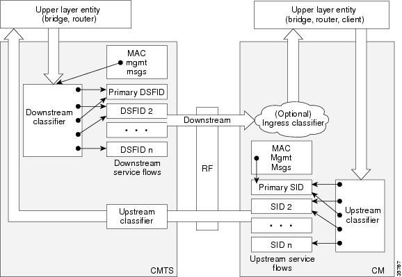
In DOCSIS 1.0 networks, a cable modem used only one set of QoS parameters for all of its traffic, so the CMTS simply had to route packets to and from the appropriate cable modems. In DOCSIS 1.1 networks, however, cable modems can be using multiple service flows, and each service flow can be given a different level of service. To quickly assign upstream and downstream packets to their proper service flows, the CMTS uses the concept of packet classifiers.
Each packet classifier specifies one or more packet header attributes, such as source MAC address, destination IP address, or protocol type. The classifier also specifies the service flow to be used when a packet matches this particular combination of headers. Separate classifiers are used for downstream and upstream service flows.
When the CMTS receives downstream and upstream packets, it compares each packet's headers to the contents of each packet classifier. When the CMTS matches the packet to a classifier, the CMTS then assigns the proper SFID to the packet and transmits the packet to or from the cable modem. This ensures that the packet is assigned its proper service flow, and thus its proper QoS parameters.
Figure 1 illustrates the mapping of packet classifiers.
Figure 1 Classification Within the MAC Layer
Packet Header Suppression Rules
Because many data and real-time applications may use fixed values in their packet header fields, DOCSIS 1.1 supports PHS to suppress the duplicate portions of the packet headers when a group of packets is transmitted during a session. Each service flow can support a separate set of PHS rules that determine which parts of the header are suppressed.
When PHS is being used, the transmitting CMTS suppresses the specified headers in all the packets for that service flow. The receiving CMTS then restores the missing headers before forwarding the packets on to their ultimate destination.
Proper use of PHS can increase the efficiency of packetized transmissions, especially for real-time data that is encapsulated by other protocols, such as VoIP traffic.
Quality of Service Comparison
This section summarizes the differences in QoS between DOCSIS 1.0, DOCSIS 1.0+, and DOCSIS 1.1 networks.
Note
DOCSIS 1.0
DOCSIS1.0 uses a static QoS model that is based on a class of service (CoS) that is preprovisioned in the DOCSIS configuration file that is downloaded to the cable modem. The CoS is a bidirectional QoS profile that applies to both the upstream and downstream directions, and that has limited control, such as peak rate limits in either direction, and relative priority on the upstream.
DOCSIS 1.0 defines the concept of a service identifier (SID), which identifies the cable modems that are allowed to transmit on the network. In DOCSIS 1.0 networks, each cable modem is assigned only one SID for both the upstream and downstream directions, creating a one-to-one correspondence between a cable modem and its SID. All traffic originating from, or destined for, a cable modem is mapped to that particular SID.
Typically, a DOCSIS 1.0 cable modem has one CoS and treats all traffic the same, which means that data traffic on a cable modem can interfere with the quality of a voice call in progress. The CMTS, however, has a limited ability to prioritize downstream traffic based on IP precedent type-of-service (ToS) bits.
For example, voice calls using higher IP precedence bits receive a higher queueing priority (but without a guaranteed bandwidth or rate of service). A DOCSIS 1.0 cable modem could increase voice call quality by permanently reserving bandwidth for voice calls, but then that bandwidth would be wasted whenever a voice call is not in progress.
DOCSIS 1.0+
In response to the limitations of DOCSIS 1.0 networks in handling real-time traffic, such as voice calls, Cisco created the DOCSIS 1.0+ extensions to provide the more important QoS enhancements that were expected in DOCSIS 1.1. In particular, the DOCSIS 1.0+ enhancements provide basic Voice-over-IP (VoIP) service over the DOCSIS link.
Cisco's DOCSIS 1.0+ extensions include the following DOCSIS 1.1 features:
•
•
•
•
•
Caution
Interoperability with Different Versions of DOCSIS Networks
DOCSIS 1.1 cable modems have additional features and better performance than earlier DOCSIS 1.0 and 1.0+ models, but all three models can coexist in the same network. DOCSIS 1.0 and 1.0+ cable modems will not hamper the performance of a DOCSIS 1.1 CMTS, nor will they interfere with operation of DOCSIS 1.1 features.
Table 1 shows the interoperability of a DOCSIS 1.1 CMTS with different versions of cable modems.
Enhanced Rate Bandwidth Allocation (ERBA) Support for DOCSIS 1.0 Cable Modems
Cisco IOS release 12.3(13a)BC introduces Enhanced Rate Bandwidth Allocation (ERBA) support for DOCSIS 1.0 cable modems on the Cisco uBR7246VXR router. Cisco IOS release 12.3(21)BC extends this support to the Cisco uBR10012 router with Performance Routing Engine 2 modules.
The ERBA feature in Cisco IOS release 12.3(21)BC is characterized by the following enhancements:
•
•
ERBA allows DOCSIS1.0 modems to burst their temporary transmission rate up to the full line rate for short durations of time. This capability provides higher bandwidth for instantaneous bandwidth requests, such as those in Internet downloads, without having to make changes to existing service levels in the QoS Profile.
This feature allows you to set the DOCSIS 1.0 cable modems burst transmissions, with mapping to overriding DOCSIS 1.1 QoS profile parameters on the Cisco CMTS. DOCSIS 1.0 cable modems require DOCSIS 1.0 parameters when registering to a matching QoS profile. This feature enables maximum downstream line rates, and the ERBA setting applies to all cable modems that register to the corresponding QoS profile.
Note
ERBA for DOCSIS 1.0 cable modems is supported with these new or enhanced commands or keywords:
•
•
DOCSIS 3.0 Downstream Peak Traffic Rate TLV Support for ERBA
The downstream peak traffic rate TLV (DOCSIS 3.0 TLV 25.27) support for the ERBA feature was introduced in Cisco IOS Release 12.2(33)SCB1 for the Cisco uBR10012 router. This feature support was extended to Cisco uBR7246VXR and Cisco uBR7225VXR routers in Cisco IOS Release 12.2(33)SCD.
The DOCSIS WFQ Scheduler allows each service flow to have one dedicated queue. When ERBA is enabled for the service flow, the peak rate is implemented as the queue shape rate within the scheduler, while the maximum sustained rate is set as the token bucket refill rate. When ERBA is turned off, the burst size and the peak rate value are not used.
The maximum traffic burst parameter is used to control a service flow burst duration, to burst up to the channel line rate or a configured peak rate, when it is within its maximum burst size allowance. On the Cisco uBR10012 Universal Broadband Router, the cable ds-max-burst command is used to control this behavior explicitly.
In Cisco IOS Release 12.2(33)SCB1, the peak-rate keyword was introduced to specify the peak rate an ERBA-enabled service flow can use. The peak rate value is a global value and is applied to all service flows created after the configuration of the cable ds-max-burst command.
If the DOCSIS 3.0 TLV 25.27 is specified for a service flow, the peak rate value is set as the TLV value. However, if ERBA is not turned on for a service flow, the peak rate value is ignored.
The peak rate value can also be configured using the cable service class command, which forms part of the service class template. During modem registration or Dynamic Service Addition (DSA) operation, the service class name TLV 25.4 is sent to create the static or dynamic downstream service flow that matches the service class template. These downstream service flows are created with a specific peak rate. If the peak rate is not specified, then the value specified by the cable ds-max-burst command is used.
If a service flow has both service class and TLV 25.27 defined peak rate, then the peak rate value specified in the TLV is used.
Some of the DOCSIS 1.x an DOCSIS 2.0 cable modems, which are not fully DOCSIS 1.x or DOCSIS 2.0 compliant, may fail to come online when the downstream peak rate TLV 25.27 is received from the CMTS during registration. To overcome this failure, you can configure the cable service attribute withhold-TLVs command to restrict sending of the peak traffic rate TLVs to DOCSIS1.x and DOCSIS 2.0 cable modems. For more information on how to suppress peak rate TLVs, see Suppressing Upstream and Downstream Peak Rate TLVs for pre DOCSIS 3.0 Cable Modems.
Note
Table 2 summarizes the ERBA support for the Cisco uBR10012 router.
In Cisco uBR7246VXR and Cisco uBR7225VXR routers, the dual token bucket-based shaper is used to support ERBA on the Cisco uBR-MC88V line card (the ERBA feature is always enabled on the Cisco uBR-MC88V line card). The dual token bucket shaper has two independent token buckets for each service flow. The maximum rate of one bucket is configured to MSR and the maximum tokens are set to maximum traffic burst. The other bucket is configured with the refilling rate of the peak rate and the maximum tokens are set to the default level of 4 milliseconds. Packets are shaped if any of the two buckets are exhausted.
Table 3 summarizes the ERBA dual token bucket configuration for the Cisco uBR7246VXR and Cisco uBR7225VXR routers.
Note
Suppressing Upstream and Downstream Peak Rate TLVs for pre DOCSIS 3.0 Cable Modems
The DOCSIS 3.0 upstream (US) peak rate TLV 24.27 and downstream (DS) peak rate TLV 25.27 are enabled on the Cisco CMTS through the cable service class command or the CM configuration file. The DOCSIS 1.x and DOCSIS 2.0 CMs do not support these TLVs. Ideally, if a DOCSIS 1.x or DOCSIS 2.0 CM receives peak rate TLVs during registration, it should ignore these TLVs and proceed with the registration. However there are a few old non-compliant pre DOCSIS 3.0 CMs, which may fail to come online when peak-rate TLVs are received in the registration response from the Cisco CMTS. To overcome this, the Cisco CMTS enables suppression of the DOCSIS 3.0 peak rate TLVs for the pre-DOCSIS3.0 CMs.
To suppress the DOCSIS 3.0 US and DS peak rate TLVs, use the cable service attribute withhold-TLVs command with the peak-rate keyword in global configuration mode. When configured, this command restricts the Cisco CMTS from sending US and DS peak rate TLVs to the DOCSIS 1.x and DOCSIS 2.0 CMs. The decision to send the TLVs is based on the DOCSIS version of the CM received during registration. If the registration request is from a pre DOCSIS 3.0 CM, the peak rate TLVs are not sent in the registration response. However this command does not restrict sending of DOCSIS 3.0 peak-rate TLVs to DOCSIS 3.0 CMs.
For more information on the cable service attribute withhold-TLVs command, see Cisco IOS CMTS Cable Command Reference Guide.
Benefits
DOCSIS 1.1 includes a rich set of features that provide advanced and flexible QoS capabilities for various types of traffic (voice, data, and video) over the cable network. It also provides enhanced security and authentication features.
Baseline Privacy Interface Plus Enhancement
The Plus (+) version of the Baseline Privacy Interface (BPI+) in DOCSIS 1.1 provides a set of extended services within the MAC sublayer that increase performance and system security. Digital certificates provide secure authentication for each cable modem, to prevent identity theft on the basis of MAC and IP addresses. Advanced encryption provides a secure channel between the cable modem and CMTS, and secure software download allows a service provider to upgrade the software on cable modems, without the threat of interception, interference, or alteration of the software code.
Dynamic Service Flows
The dynamic creation, modification, and deletion of service flows allows for on-demand reservation on Layer 2 bandwidth resources. The CMTS can now provide special QoS to the cable modem dynamically for the duration of a voice call or video session, as opposed to the static provisioning and reservation of resources at the time of cable modem registration. This provides a more efficient use of the available bandwidth.
Concatenation
The cable modem concatenates multiple upstream packets into one larger MAC data frame, allowing the cable modem to make only one time-slot request for the entire concatenated MAC frame, as opposed to requesting a time slot for each packet. This reduces the delay in transferring the packet burst upstream.
Enhanced QoS
Extensive scheduling parameters allow the CMTS and the cable modem to communicate QoS requirements and achieve more sophisticated QoS on a per service-flow level.
Different new time-slot scheduling disciplines help in providing guaranteed delay and jitter bound on shared upstream. Activity detection helps to conserve link bandwidth by not issuing time slots for an inactive service flow. The conserved bandwidth can then be reused for other best-effort data slots.
Packet classification helps the CMTS and cable modem to isolate different types of traffic into different DOCSIS service flows. Each flow could be receiving a different QoS service from CMTS.
Fragmentation
Fragmentation splits large data packets so that they fit into the smaller time slots inbetween UGS slots. This reduces the jitter experienced by voice packets when large data packets are transmitted on the shared upstream channel and preempt the UGS slots used for voice.
Multiple Subflows per SID
This feature allows the cable modem to have multiple calls on a single hardware queue. This approach scales much better than requiring a separate SID hardware queue on the cable modem for each voice call.
Payload Header Suppression
Payload Header Suppression (PHS) allows the CMTS and cable modem to suppress repetitive or redundant portions in packet headers before transmitting on the DOCSIS link. This conserves link bandwidth, especially with types of traffic such as voice, where the header size tends to be as large as the size of the actual packet.
Service Classes
The use of the service class provides the following benefits for a DOCSIS 1.1 network:
•
•
•
Note
How to Configure the Cisco CMTS for DOCSIS 1.1 Operations
See the following sections for the configuration tasks for DOCSIS 1.1 operations. Each task in the list is identified as either required or optional.
•
•
•
•
•
•
Note
Configuring Baseline Privacy Interface
BPI+ encryption is by default enabled for 56-bit DES encryption on all cable interfaces. If BPI+ encryption has been previously disabled, or if you want to reconfigure BPI+ encryption on a cable interface on the CMTS, use the following procedure.
Note
Prerequisites
BPI+ encryption is supported on all Cisco CMTS images that include "k1", "k8", or "k9" in its file name or BPI in the feature set description. All BPI images support 40-bit and 56-bit DES encryption.
By default, BPI+ encryption is enabled for 56-bit DES encryption. Also, when a cable modem is running DOCSIS 1.1 software, BPI+ encryption is enabled by default, unless the service provider has disabled it by setting the Privacy Enable field (TLV 29) in the DOCSIS configuration file to 0. Therefore, both the CMTS and cable modem are set to use BPI+ encryption when using the default configurations.
SUMMARY STEPS
1.
2.
3.
4.
5.
6.
Caution
7.
8.
9.
10.
11.
12.
13.
14.
DETAILED STEPS
Step 1
enable
Example:Router> enable
Router#
Enables privileged EXEC mode. Enter your password if prompted.
Step 2
configure terminal
Example:Router# configure terminal
Router(config)#
Enters global configuration mode.
Step 3
interface cable x/y
Example:Router(config)# interface cable 6/0
Router(config-if)#
Enters interface configuration mode for the cable interface line card at this particular slot.
Step 4
cable privacy
Example:Router(config-if)# cable privacy
Router(config-if)#
(Optional) Enables BPI+ 56-bit DES encryption on the cable interface (default).
Step 5
cable privacy 40-bit-des
Example:Router(config-if)# cable privacy 48-bit-des
Router(config-if)#
(Optional) Enables BPI+ 40-bit DES encryption on the cable interface. Cisco does not recommend this option for production systems because 40-bit encryption is not as secure as the 56-bit DES or 168-bit 3DES encryption algorithms.
Step 6
cable privacy accept-self-signed-certificate
Example:Router(config-if)# cable privacy accept-self-signed-certificate
Router(config-if)#
(Optional) Allows cable modems to register using self-signed manufacturer certificates, as opposed to the default of allowing only manufacturer's certificates that are chained to the DOCSIS root certificate.
Caution
Note
Step 7
cable privacy authenticate-modem
Example:Router(config-if)# cable privacy authenticate-modem
Router(config-if)#
(Optional) Enables BPI+ encryption on the cable interface and uses the Cisco IOS Authentication, Authorization and Accounting (AAA) service together with BPI to authenticate the CMs.
Step 8
cable privacy authorize-multicast
Example:Router(config-if)# cable privacy authorize-multicast
Router(config-if)#
(Optional) Enables BPI+ encryption on the cable interface and uses AAA protocols to authorize all multicast stream (IGMP) join requests.
Note
Step 9
cable privacy mandatory
Example:Router(config-if)# cable privacy mandatory
Router(config-if)#
(Optional) Requires baseline privacy be active for all CMs with BPI/BPI+ enabled in the DOCSIS configuration files, else the CMs are forced to go offline.
If a CM does not have BPI enabled in its DOCSIS configuration file, it will be allowed to come online without BPI.
Step 10
cable privacy oaep-support
Example:Router(config-if)# cable privacy oaep-support
Router(config-if)#
(Optional) Enables BPI+ encryption on the cable interface and enables Optimal Asymmetric Encryption Padding (OAEP). This option is enabled by default. Disabling this option could have a performance impact.
Step 11
cable privacy kek {life-time seconds}
Example:Router(config-if)# cable privacy kek life-time 302400
Router(config-if)#
(Optional) Configures the life-time values for the key encryption keys (KEKs) for BPI+ operations on all cable interfaces.
•
Step 12
cable privacy tek {life-time seconds}
Example:Router(config-if)# cable privacy tek life-time 86400
Router(config-if)#
(Optional) Configures the life-time values for the traffic encryption keys (TEKs) for BPI+ operations on all cable interfaces.
•
Step 13
exit
Example:Router(config-if)# exit
Router(config)#
Exits interface configuration mode.
Note
Step 14
exit
Example:Router(config)# exit
Router#
Exits global configuration mode.
You can also configure the following additional timers for BPI+ operations in the DOCSIS configuration file for each cable modem. As a general rule, you do not need to specify these timers in the DOCSIS configuration file unless you have a specific reason for changing them from their default values.
Downloading the DOCSIS Root Certificate to the CMTS
DOCSIS 1.1 allows cable modems to identify themselves using a manufacturer's chained X.509 digital certificate that is chained to the DOCSIS root certificate. The DOCSIS root certificate is already installed on the bootflash of the CMTS router. However, if you want to install another root certificate, for example, the Euro-Docsis certificate, download the certificate and save it on the bootflash as "euro-root-cert".
Tip
http://www.verisign.com/products-services/index.html
Note
In prior Cisco IOS Releases, with the prior limitation, EuroDOCSIS or PacketCable devices could still come online, however, if they used self-signed manufacturer's digital certificates.
To download the DOCSIS root certificate to the Cisco CMTS, which is required if any cable modems on the network are using chained certificates, use the following procedure:
Step 1
http://www.verisign.com/products-services/index.htmlStep 2
Tip
Step 3
Router> enablePassword: <password>Router#Step 4
Router# dir bootflash:Directory of bootflash:/1 -rw- 3229188 Dec 30 2002 15:53:23 ubr7200-boot-mz.122-11.BC2.bin3407872 bytes total (250824 bytes free)Router#
Tip
Step 5
Router# copy tftp bootflash:Address or name of remote host []? tftp-server-ip-addressSource filename []? CableLabs_DOCSIS.509Destination filename [CableLabs_DOCSIS.509]? root-certLoading CableLabs_DOCSIS.509 from tftp-server-ip-address (via FastEthernet0/0): ![OK - 996/1024 bytes]996 bytes copied in 4.104 secs (249 bytes/sec)Router#
Tip
Step 6
Router# dir bootflash:Directory of bootflash:/1 -rw- 3229188 Dec 30 2002 15:53:23 ubr7200-boot-mz.122-11.BC2.bin2 -rw- 996 Mar 06 2002 16:03:46 root-cert3408876 bytes total (248696 zxbytes free)Router#Step 7
Note
Router# show crypto ca trustpointsRoot certificateStatus: AvailableCertificate Serial Number: D54BB68FE934324F6B8FD0E41A65D867Key Usage: General PurposeIssuer:CN = DOCSIS Cable Modem Root Certificate AuthorityOU = Cable ModemsO = Data Over Cable Service Interface SpecificationsC = USSubject Name:CN = "BPI Cable Modem Root Certificate Authority "OU = DOCSISO = BPIC = USValidity Date:start date: 07:00:00 UTC Mar 27 2001end date: 06:59:59 UTC Jan 1 2007
Tip
Adding a Manufacturer's Certificate as a Trusted Certificate
To DOCSIS specifications allow operators to control which manufacturer's and CM certificates are allowed on each CMTS by marking them as either trusted or untrusted. You can add a certificate to the list of trusted certificates on the Cisco CMTS using either CLI commands or SNMP commands, as described in the following sections:
•
•
Note
Adding a Certificate as a Trusted Certificate Using the Command Line Interface
To add a manufacturer's certificate to the list of trusted certificates on the CMTS, use the following procedure:
SUMMARY STEPS
1.
2.
3.
4.
DETAILED STEPS
Adding a Certificate as a Trusted Certificate Using SNMP Commands
You can also use an SNMP manager to create and add certificates to the CMTS list of trusted certificates by manipulating the tables and attributes in the DOCS-BPI-PLUS-MIB. To add a manufacturer's certificate, add an entry to the docsBpi2CmtsCACertTable table. Specify the following attributes for each entry:
•
•
•
Similarly, to add a CM certificate to the list of trusted certificates, add an entry to the docsBpi2CmtsProvisionedCmCertTable table. Specify the following attributes for each entry:
•
•
•
Tip
For example, to use the Unix command-line SNMP utility to add a manufacturer's certificate to the list of trusted certificates on the CMTS at IP address 192.168.100.134, enter the following command (be sure to substitute a valid index pointer for the table entry for the <index> value).
% setany -v2c 192.168.100.134 private docsBpi2CmtsCACertStatus.<index> -i 4
docsBpi2CmtsCACert.<index> -o '<hex_data>' docsBpi2CmtsCACertTrust.<index> -i 1
To do the same thing for a CM certificate, use the following command:
% setany -v2c 192.168.100.134 private docsBpi2CmtsProvisionedCmCertStatus.<index> -i 4
docsBpi2CmtsProvisionedCmCert.<index> -o '<hex_data>'
docsBpi2CmtsProvisionedCmCertTrust.<index> -i 1
Tip
Note
Adding a Manufacturer's or CM Certificate to the Hotlist
The DOCSIS specifications allow operators to add a digital mnufacturer's or CM certificate to a hotlist (also known as the certificate revocation list, or CRL) on the CMTS, to indicate that this particular certificate should no longer be accepted. This might be done when a user reports that their cable modem has been stolen, or when the service provider decides not to support a particular manufacturer's brand of cable modems.
You can add a certificate to the hotlist on the Cisco CMTS using either CLI commands or SNMP commands, as described in the following sections:
•
•
Note
Adding a Certificate to the Hotlist Using the Command Line Interface
To add a manufacturer's or CM certificate to the certificate hotlist on a Cisco uBR7100 series or Cisco uBR7200 series router, use the following procedure.
Note
Use the following section, Adding a Certificate to the Hotlist Using SNMP Commands, to add certificates to the hotlist on the Cisco uBR10012 router.
SUMMARY STEPS
1.
2.
3.
4.
DETAILED STEPS
Cable modems that use a MAC address or a certificate of the manufacturer that matches the one in the hotlist will not be allowed to register. For example, the following command will put the certificate of the manufacturer with the indicated serial number in the hotlist, preventing any cable modem that uses that certificate from registering:
Router# config terminalRouter(config)# cable privacy hotlist cm 00 00 0C 0a 0b 0cOct 31 13:06:29.112: Successfully added CM hotlist 0000.0C0A.0B0CRouter#The following command will put the manufacturer's certificate with the indicated serial number in the hotlist, preventing any cable modem that uses that manufacturer's certificate from registering:
Router(config)# cable privacy hotlist manufacturer 00 90 83 00 00 00 00 01Oct 31 13:06:34.478: Successfully added MFG hotlist 00 90 83 00 00 00 00 01Router(config)# exitRouter#To remove a cable modem or certificate from the hotlist, add the no prefix to the command. For example:
Router# config terminalRouter(config)# no cable privacy hotlist cm 00 00 0C 0a 0b 0cRouter(config)# no cable privacy hotlist manufacturer 00 90 83 00 00 00 00 01Router(config)# exitRouter#Adding a Certificate to the Hotlist Using SNMP Commands
You can also use an SNMP manager to create and add certificates to the hotlist by manipulating the tables and attributes in the DOCS-BPI-PLUS-MIB. To add a manufacturer's certificate, add an entry to the docsBpi2CmtsCACertTable table. Specify the following attributes for each entry:
•
•
•
Similarly, to add a CM certificate to the hotlist, add an entry to the docsBpi2CmtsProvisionedCmCertTable table. Specify the following attributes for each entry:
•
•
•
Tip
Note
For example, to use the Unix command-line SNMP utility to add a manufacturer's certificate to the hotlist on the CMTS at IP address 192.168.100.113, enter the following command (be sure to substitute a valid index pointer for the table entry for the <index> value).
% setany -v2c 192.168.100.113 private docsBpi2CmtsCACertStatus.<index> -i 4
docsBpi2CmtsCACert.<index> -o '<hex_data>' docsBpi2CmtsCACertTrust.<index> -i 2
To do the same thing for a CM certificate, use the following command:
% setany -v2c 192.168.100.113 private docsBpi2CmtsProvisionedCmCertStatus.<index> -i 4
docsBpi2CmtsProvisionedCmCert.<index> -o '<hex_data>'
docsBpi2CmtsProvisionedCmCertTrust.<index> -i 2
Tip
Enabling Concatenation
To enable concatenation for one or more upstreams on a cable interface (which is the default configuration), use the following procedure:
SUMMARY STEPS
1.
2.
3.
4.
5.
6.
DETAILED STEPS
Enabling DOCSIS Fragmentation
To enable DOCSIS fragmentation for one or more upstreams on a cable interface (which is the default configuration), use the following procedure:
SUMMARY STEPS
1.
2.
3.
4.
5.
6.
7.
DETAILED STEPS
Configuring Downstream ERBA Settings for DOCSIS 1.0 Cable Modems
To define ERBA on the downstream for DOCSIS 1.0 cable modems, use the cable qos promax-ds-burst command in global configuration mode. To remove this ERBA setting from the QoS profile, use the no form of this command.
cable qos pro max-ds-burst burst-size
no cable qos pro max-ds-burst
Syntax Description
To display ERBA settings as applied to DOCSIS 1.0 cable modems and QoS profiles on the Cisco CMTS, use the show cable qos profile command in Privileged EXEC mode.
The following example of the cable qos profile command in global configuration mode illustrates changes to the cable qos profile command. Fields relating to the ERBA feature are shown in bold for illustration:
Router(config)# cable qos pro 10 ?grant-interval Grant intervalgrant-size Grant sizeguaranteed-upstream Guaranteed Upstreammax-burst Max Upstream Tx Burstmax-ds-burst Max Downstream Tx burst (cisco specific)max-downstream Max Downstreammax-upstream Max Upstreamname QoS Profile name string (cisco specific)priority Priorityprivacy Cable Baseline Privacy Enabletos-overwrite Overwrite TOS byte by setting mask bits to valueThe following example of the show cable qos profile command illustrates that the maximum downstream burst has been defined, and is a management-created QoS profile:
Router# show cable qos proID Prio Max Guarantee Max Max TOS TOS Create B IP prec.upstream upstream downstream tx mask value by priv ratebandwidth bandwidth bandwidth burst enab enab1 0 0 0 0 0 0xFF 0x0 cmts(r) no no2 0 64000 0 1000000 0 0xFF 0x0 cmts(r) no no3 7 31200 31200 0 0 0xFF 0x0 cmts yes no4 7 87200 87200 0 0 0xFF 0x0 cmts yes no6 1 90000 0 90000 1522 0xFF 0x0 mgmt yes no10 1 90000 0 90000 1522 0x1 0xA0 mgmt no no50 0 0 0 96000 0 0xFF 0x0 mgmt no no51 0 0 0 97000 0 0xFF 0x0 mgmt no noThe following example illustrates the maximum downstream burst size in sample QoS profile 10 with the show cable qos prof verbose command in privileged EXEC mode:
Router# show cable qos pro 10 verProfile Index 10NameUpstream Traffic Priority 1Upstream Maximum Rate (bps) 90000Upstream Guaranteed Rate (bps) 0Unsolicited Grant Size (bytes) 0Unsolicited Grant Interval (usecs) 0Upstream Maximum Transmit Burst (bytes) 1522Downstreamam Maximum Transmit Burst (bytes) 100000IP Type of Service Overwrite Mask 0x1IP Type of Service Overwrite Value 0xA0Downstream Maximum Rate (bps) 90000Created By mgmtBaseline Privacy Enabled noUsage Guidelines
If a cable modem registers with a QoS profile that matches one of the existing QoS profiles on the Cisco CMTS, then the maximum downstream burst size, as defined for that profile, is used instead of the default DOCSIS QoS profile of 1522.
For example, a DOCSIS 1.0 configuration that matches QoS profile 10 in the previous examples would be as follows:
03 (Net Access Control) = 104 (Class of Service Encodings Block)S01 (Class ID) = 1S02 (Maximum DS rate) = 90000S03 (Maximum US rate) = 90000S06 (US burst) = 1522S04 (US Channel Priority) = 1S07 (Privacy Enable) = 0The maximum downstream burst size (as well as the ToS overwrite values) are not explicitly defined in the QoS configuration file because they are not defined in DOCSIS. However, because all other parameters are a perfect match to profile 10 in this example, then any cable modem that registers with these QoS parameters has a maximum downstream burst of 100000 bytes applied to it.
For further illustration, consider a scenario in which packets are set in lengths of 1000 bytes at 100 packets per second (pps). Therefore, the total rate is a multiplied total of 1000, 100, and 8, or 800kbps.
To change these settings, two or more traffic profiles are defined, with differing downstream QoS settings as desired. Table 5 provides two examples of such QoS profiles for illustration:
In this scenario, both QoS profiles are identical except for the max-ds-burst size, which is set to 4000 in QoS profile 101 and 5000 in QoS profile 102.
Optimal Settings for DOCSIS 1.0 Downstream Powerburst
DOCSIS allows the setting different token bucket parameters for each service flow, including the token bucket burst size. When burst sizes are closer to 0, QoS is enforced in a stricter manner, allowing a more predictable sharing of network resources, and as a result easier network planning.
When burst sizes are larger, individual flows can transmit information faster (lower latency), although the latency variance can be larger as well.
For individual flows, a larger burst size is likely to be better. As long as the system is not congested, a large burst size reduces the chances of two flows transmitting at the same time, because each burst is likely to take less time to transmit.
For additional information about the cable qos profile command and configuring QoS profiles, refer to the following documents on Cisco.com:
•
http://www.cisco.com/en/US/docs/ios/cable/command/reference/cbl_book.html
Enabling DOCSIS 1.1 Downstream Maximum Transmit Burst on the Cisco uBR10012 Router
Perform the following steps to configure ERBA on the Cisco uBR10012 router with PRE2 or PRE4 modules and Cisco IOS Release 12.3(21)BC or Cisco IOS Release 12.2(33)SCB or later releases. This procedure and the associated commands are subject to the guidelines and restrictions cited in this document.
Restrictions
The cable ds-max-burst and related commands are supported strictly on the Cisco uBR10012 router with PRE2 or PRE4 modules and Cisco IOS Release 12.3(21)BC or Cisco IOS Release 12.2(33)SCB or later releases.
SUMMARY STEPS
1.
2.
3.
4.
5.
DETAILED STEPS
Examples
When this feature is enabled, new service flows with burst size larger than the burst threshold are supported. However, the existing service flows are not affected.
When this feature is disabled, no new service flows are configured with the Downstream Maximum Transmit Burst parameter—the cable ds-max-burst command settings. However, the existing service flows are not affected.
The following example illustrates the cable ds max-burst command on the Cisco uBR10012 router in Cisco IOS Release 12.3(21)BC:
Router(config)# cable ds-max-burst burst-threshold 2048The following example illustrates configuration of the ERBA maximum burst for the specified service flow:
Router# sh cr10k-rp c7/0/0 1 service-flow dsRP SFID LC SFID Conform Conform Exceed Exceed Total Total QIDBytes Pkts Bytes Pkts Bytes Pkts32781 4 538 1 0 0 538 1 279 #32782 4 0 0 0 0 0 0 0#: DS max burst enabledThe following example illustrates the cable ds max-burst command on the Cisco uBR10012 router in Cisco IOS Release 12.2(33)SCB:
Router(config)# cable ds-max-burst burst-threshold 2048 peak-rate 1000The following example illustrates configuration of the ERBA maximum burst for the specified service flow:
Router# sh cr10k-rp c7/0/0 1 service-flow dsRP SFID LC SFID Conform Exceed Conform Exceed Total QIDXmit Pkts Xmit Pkts Drop Pkts Drop Pkts Pkts32930 10 41 0 0 0 41 131349Forwarding interface: Modular-Cable1/0/0:032931 13 0 0 0 0 0 131350Forwarding interface: Modular-Cable1/0/0:0Monitoring DOCSIS Operations
The following sections describe the commands that provide information about the DOCSIS network and its cable modems, the RF network and cable interfaces on the CMTS, and BPI+ operations.
•
•
Monitoring the DOCSIS Network
The show cable modem command is the primary command to display the current state of cable modems and the DOCSIS network. This command has many options that provide information on different aspects of DOCSIS operations.
•
•
•
•
Tip
Displaying the Status of Cable Modems
The following sample output from the show cable modem command shows a list of known cable modems and their current status.
Router# show cable modemsMAC Address IP Address I/F MAC Prim RxPwr Timing Num BPIState Sid (db) Offset CPE Enb0010.9507.01db 144.205.151.130 C5/1/0/U5 online(pt) 1 0.25 938 1 Y0080.37b8.e99b 144.205.151.131 C5/1/0/U5 online 2 -0.25 1268 0 N0002.fdfa.12ef 144.205.151.232 C6/1/0/U0 online(pt) 13 -0.25 1920 1 Y0002.fdfa.137d 144.205.151.160 C6/1/0/U0 online 16 -0.50 1920 1 N0003.e38f.e9ab 144.205.151.237 C6/1/0/U0 online 3 -0.50 1926 1 N0003.e3a6.8173 144.205.151.179 C6/1/1/U2 offline 4 0.50 1929 0 N0003.e3a6.8195 144.205.151.219 C6/1/1/U2 online(pt) 22 -0.50 1929 1 Y0006.28dc.37fd 144.205.151.244 C6/1/1/U2 online(pt) 61 0.00 1925 2 Y0006.28e9.81c9 144.205.151.138 C6/1/1/U2 online(pt) 2 !0.75 1925 1 Y0006.28f9.8bbd 144.205.151.134 C6/1/1/U2 #online 25 -0.25 1924 1 N0002.fdfa.12db 144.205.151.234 C7/0/0/U0 online 15 -0.75 1914 1 N0002.fdfa.138d 144.205.151.140 C7/0/0/U5 online 4 0.00 1917 1 N0003.e38f.e85b 144.205.151.214 C7/0/0/U5 online 17 *0.25 1919 1 NRouter#You can also display a particular cable modem by specifying its MAC address or IP address with the show cable modem command. If you specify the MAC address or IP address for a CPE device, the command will display the information for the cable modem that is associated with that device.
Note
Router# show cable modem 0010.7bb3.fcd1MAC Address IP Address I/F MAC Prim RxPwr Timing Num BPIState Sid (db) Offset CPEs Enbld0010.7bb3.fcd1 10.20.113.2 C5/0/U5 online 1 0.00 1624 0 yesRouter#To display a list of cable modems sorted by their manufacturer, use the vendor option.
Router# show cable modem vendorVendor MAC Address I/F MAC Prim RxPwr Timing Num BPIState Sid (db) Offset CPE EnbThomson 0010.9507.01db C5/1/0/U5 online 1 0.00 938 1 NEricsson 0080.37b8.e99b C5/1/0/U5 online 2 -0.25 1268 0 NCisco 0002.fdfa.12ef C6/1/0/U0 online 13 0.00 1920 1 NCisco 0002.fdfa.137d C6/1/0/U0 online 16 -0.50 1920 1 NCisco 0003.e38f.e9ab C6/1/0/U0 online 3 -0.25 1926 1 NCisco 0003.e3a6.7f69 C6/1/0/U0 online 15 0.50 1927 1 NCisco 0003.e3a6.816d C6/1/0/U0 online 4 0.00 1929 1 NCisco 0006.28f9.8be5 C6/1/0/U0 online 12 0.75 1922 1 NCisco 0001.9659.519f C6/1/1/U2 online 26 0.25 1930 1 NCisco 0002.b96f.fdbb C6/1/1/U2 online 29 -0.75 1929 1 NCisco 0002.b96f.fdf9 C6/1/1/U2 online 39 -0.50 1931 1 NCisco 0002.fdfa.12e9 C6/1/1/U2 online 5 -0.25 1925 1 NMotorola 0020.4005.3f06 C7/0/0/U0 online 2 0.00 1901 1 NMotorola 0020.4006.b010 C7/0/0/U5 online 3 0.25 1901 1 NCisco 0050.7302.3d83 C7/0/0/U0 online 18 -0.25 1543 1 NCisco 00b0.6478.ae8d C7/0/0/U5 online 44 0.50 1920 21 NCisco 00d0.bad3.c0cd C7/0/0/U5 online 19 0.00 1543 1 NRouter#The MAC state field in each of these displays shows the current state of the cable modem:
Displaying a Summary Report for the Cable Modems
The show cable modem command also can provide a summary report of the cable modems by using the summary and total options.
Router# show cable modem summaryInterface Cable ModemTotal Registered Unregistered OfflineCable5/1/0/U5 2 2 0 0Cable6/1/0/U0 14 13 1 0Cable6/1/1/U2 14 14 0 0Cable7/0/0/U0 2 2 0 0Cable7/0/0/U5 4 3 1 1Router# show cable modem summary totalInterface Cable ModemTotal Registered Unregistered OfflineCable5/1/0/U5 2 2 0 0Cable6/1/0/U0 14 13 1 0Cable6/1/1/U2 14 14 0 0Cable7/0/0/U0 2 2 0 0Cable7/0/0/U5 4 3 1 1Total: 36 34 2 1Router#You can also use the summary and total options to display information for a single interface or a range of interfaces.
Router# show cable modem summary c5/0 totalInterface Total Active RegisteredModems Modems ModemsCable5/0/U0 294 272 271Cable5/0/U1 256 248 246Cable5/0/U2 196 194 194Total: 746 714 711Router# show cable modem summary c6/1/1 c7/0/0 totalInterface Cable ModemTotal Registered Unregistered OfflineCable6/1/1/U2 14 14 0 0Cable7/0/0/U0 2 2 0 0Cable7/0/0/U5 4 3 1 1Total: 20 19 1 1Displaying the Capabilities of the Cable Modems
To display the capabilities and current DOCSIS provisioning for cable modems, use the mac option.
Router# show cable modem macMAC Address MAC Prim Ver Prov Frag Concat PHS Priv DS USState Sid Saids Sids0010.64ff.e4ad online 1 DOC1.1 DOC1.0 yes yes yes BPI+ 0 40010.f025.1bd9 init(rc) 2 DOC1.0 DOC1.0 no no no BPI 0 00010.9659.4447 online(pt) 3 DOC1.0 DOC1.0 no yes no BPI 0 00010.9659.4461 online(pt) 4 DOC1.0 DOC1.0 no yes no BPI 0 00010.64ff.e459 online 5 DOC1.0 DOC1.0 no yes no BPI 0 00020.4089.7ed6 online 6 DOC1.0 DOC1.0 no no no BPI 0 00090.9607.3831 online(pt) 7 DOC1.0 DOC1.0 no no no BPI 0 00090.9607.3830 online(pt) 1 DOC1.0 DOC1.0 no no no BPI 0 00050.7366.12fb init(i) 2 DOC1.0 DOC1.0 no no no BPI 0 00010.fdfa.0a35 online(pt) 3 DOC1.1 DOC1.1 yes yes yes BPI+ 0 4Router#To get a summary report of the cable modems and their capabilities, use the mac option with the summary and total options.
Router# show cable modem mac summary totalCable Modem Summary-------------------Mac Version Provision ModeInterface Total DOC1.1 DOC1.0 Reg/Online DOC1.1 DOC1.0Cable5/1/0/U5 1 0 1 1 0 1Cable6/1/0/U0 11 0 11 8 0 8Cable6/1/1/U2 17 1 16 15 0 15Cable7/0/0/U0 2 0 2 1 0 1Cable7/0/0/U5 1 0 1 0 0 0Total: 32 1 31 25 0 25Router#Displaying Detailed Information About a Particular Cable Modem
Several options for the show cable modem command display detailed information about a particular cable modem (as identified by its MAC address). The verbose option displays the most comprehensive output.
Router# show cable modem 0010.7bb3.fcd1 verboseMAC Address : 0010.7bb3.fcd1IP Address : 10.20.113.2Prim Sid : 1Interface : C5/0/U5Upstream Power : 0 dBmV (SNR = 33.25 dBmV)Downstream Power : 0 dBmV (SNR = ----- dBmV)Timing Offset : 1624Received Power : 0.25MAC Version : DOC1.0Capabilities : {Frag=N, Concat=N, PHS=N, Priv=BPI}Sid/Said Limit : {Max Us Sids=0, Max Ds Saids=0}Optional Filtering Support : {802.1P=N, 802.1Q=N}Transmit Equalizer Support : {Taps/Symbol= 0, Num of Taps= 0}Number of CPEs : 0(Max CPEs = 0)Flaps : 373(Jun 1 13:11:01)Errors : 0 CRCs, 0 HCSesStn Mtn Failures : 0 aborts, 3 exhaustedTotal US Flows : 1(1 active)Total DS Flows : 1(1 active)Total US Data : 1452082 packets, 171344434 bytesTotal US Throughput : 0 bits/sec, 0 packets/secTotal DS Data : 1452073 packets, 171343858 bytesTotal DS Throughput : 0 bits/sec, 0 packets/secRouter#The connectivity and maintenance options also provide information that can be useful in troubleshooting problems with a particular cable modem.
The following example shows sample output for the maintenance option for a particular CM:
Router# show cable modem 0010.7bb3.fcd1 connectivityPrim 1st time Times %online Online time Offline timeSid online Online min avg max min avg max1 May 30 2000 4 99.85 48:20 11h34m 1d2h23m 00:01 00:59 03:00Router# show cable modem 0010.7bb3.fcd1 maintenanceMAC Address I/F Prim SM Exhausted SM AbortedSid Count Time Count Time0010.7bb3.fcd1 C5/0/U5 1 3 Jun 1 10:24:52 0 Jan 1 00:00:00Router#Monitoring the RF Network and Cable Interfaces
You can use the show interface cable command to display information about the operation of the RF network and the cable interfaces on the CMTS.
•
•
•
•
•
•
Tip
Displaying Information About Cloned Cable Modems
To display the list of cable modems detected as cloned, use the privacy hotlist option with the show interface cable command.
The following example shows how to display the cloned cable modems on a particular cable interface:
Router# show interface cable 5/1/0 privacy hotlistLastMAC Address Ranged On Type00a0.73b0.4c43 Oct 27 21:57:39 Permanent001a.c3ff.d2d4 Oct 27 21:57:40 Permanent0018.6852.7746 Never Permanent000e.9bb3.b946 Never PermanentRouter#Denying RF Access For Cable Modems
To deny radio frequency (RF) access for cable modems during ranging, use the cable privacy hotlist cm mac-address command.
The following example shows how to block cloned cable modems using their own MAC address:
Router(config)# cable privacy hotlist cm 00C0.0102.0304Router(config)#When an operator identifies a modem's MAC address that should not be registered on a specific CMTS, the operator can add this MAC address to the CMTS using the above command. This command ensures that the modem will not be allowed to come online on any interface on that CMTS.
Displaying Information About the Mac Scheduler
To display information about the DOCSIS MAC layer scheduler that is operating on each cable interface, use the mac-scheduler option with the show cable interface command. You can display information for all of the upstreams on an interface, or you can display information for a single upstream on an interface.
The following example shows how to display information for the second upstream (U1) on a particular cable interface:
Router# show interface cable 3/0 mac-scheduler 1DOCSIS 1.1 MAC scheduler for Cable3/0/U1Queue[Rng Polls] 0/64, 0 dropsQueue[CIR Grants] 0/64, 0 dropsQueue[BE(7) Grants] 0/64, 0 dropsQueue[BE(6) Grants] 0/64, 0 dropsQueue[BE(5) Grants] 0/64, 0 dropsQueue[BE(4) Grants] 0/64, 0 dropsQueue[BE(3) Grants] 0/64, 0 dropsQueue[BE(2) Grants] 0/64, 0 dropsQueue[BE(1) Grants] 0/64, 0 dropsQueue[BE(0) Grants] 0/64, 0 dropsReq Slots 81256509, Req/Data Slots 0Init Mtn Slots 568433, Stn Mtn Slots 68664Short Grant Slots 2261, Long Grant Slots 2064698Awacs Slots 0Fragmentation count 6Fragmentation test disabledAvg upstream channel utilization : 1%Avg percent contention slots : 97%Avg percent initial ranging slots : 2%Avg percent minislots lost on late MAPs : 0%Sched Table Adm-State: Grants 1, Reqpolls 1, Util 20%UGS : 0 SIDs, Reservation-level in bps 0UGS-AD : 1 SIDs, Reservation-level in bps 412800RTPS : 0 SIDs, Reservation-level in bps 0NRTPS : Not SupportedBE : 8 SIDs, Reservation-level in bps 0Router#Displaying Information About QoS Parameter Sets
To display information about the DOCSIS 1.1 QoS parameter sets that have been defined on a cable interface, use the qos paramset option with the show cable interface command.
Router# show interface cable 3/0 qos paramsetIndex Name Dir Sched Prio MaxSusRate MaxBurst MinRsvRate1 US BE 0 64000 0 02 DS BE 0 1000000 0 03 US BE 0 200000 1600 04 DS BE 0 1500000 1522 05 US BE 0 500000 1522 06 US UGS_AD7 DS BE 0 2000000 1522 08 US BE 0 128000 1600 09 DS BE 0 1000000 1522 010 DS BE 0 100000 1522 50000Router#You can also display detailed information for a particular parameter set by specifying the index number for its Class of Service along with the verbose option.
Router# show interface cable 3/0 qos paramset 8 verboseIndex: 8Name:Direction: UpstreamMinimum Packet Size 64 bytesAdmitted QoS Timeout 200 secondsActive QoS Timeout 0 secondsScheduling Type: Unsolicited Grant Service(AD)Request/Transmission Policy: 0x1FFNominal Polling Interval: 10000 usecsTolerated Poll Jitter: 2000 usecsUnsolicited Grant Size: 500 bytesNominal Grant Interval: 10000 usecsTolerated Grant Jitter: 2000 usecsGrants per Interval: 1IP ToS Overwrite [AND-mask,OR-mask]: 0xFF,0x0Parameter Presence Bitfield: {0x0, 0x3FC000}Router#Displaying Information About Service Flows
To display the service flows and their QoS parameter sets that are configured on a cable interface, use the service-flow option with the show interface cable command.
Router# show interface cable 3/0 service-flowSfid Sid Mac Address QoS Param Index Type Dir Curr ActiveProv Adm Act State Time4 N/A 0001.9659.4447 4 4 4 prim DS act 1d0h39m3 1 0001.9659.4447 3 3 3 prim US act 1d0h39m6 N/A 0001.64ff.e4ad 6 6 6 prim DS act 1d0h39m14 N/A 0006.2854.7319 9 9 9 prim DS act 1d0h2m457 N/A 0006.2854.7319 10 10 0 sec(S) DS adm 00:0013 6 0006.2854.7319 7 7 7 prim US act 1d0h2m456 155 0006.2854.7319 8 8 8 sec(S) US act 21h31m458 156 0006.2854.7319 0 11 11 dyn(S) US act 00:1016 N/A 0050.7366.12fb 4 4 4 prim DS act 1d0h39m15 7 0050.7366.12fb 3 3 3 prim US act 1d0h39m19 N/A 0090.9607.3831 4 4 4 prim DS act 1d0h39m23 10 0090.9607.3831 3 3 3 prim US act 1d0h39mRouter#To display the major QoS parameters for each service flow, add the qos option to this command.
Router# show interface cable 3/0 service-flow qosSfid Dir Curr Sid Sched Prio MaxSusRate MaxBrst MinRsvRate ThroughputState Type14 DS act N/A BE 0 2000000 1522 0 8124457 DS adm N/A BE 0 100000 1522 50000 013 US act 6 BE 0 500000 1522 0 0456 US act 155 UGS_A 0 0 1522 0 5764319 DS act N/A UGS 0 100000 1522 50000 68715Router#To display the complete QoS parameters for a particular service flow, use the qos and verbose options. You can use these options separately or together.
Router# show interface cable 3/0 service-flow 19 verboseSfid : 4Mac Address : 0090.9607.3831Type : PrimaryDirection : DownstreamCurrent State : ActiveCurrent QoS Indexes [Prov, Adm, Act] : [4, 4, 4]Active Time : 21h04mSid : N/ATraffic Priority : 0Maximum Sustained rate : 100000 bits/secMaximum Burst : 1522 bytesMinimum Reserved Rate : 0 bits/secAdmitted QoS Timeout : 200 secondsActive QoS Timeout : 0 secondsPackets : 130Bytes : 123096Rate Limit Delayed Grants : 0Rate Limit Dropped Grants : 0Current Throughput : 68715 bits/sec, 9 packets/secClassifiers: NONERouter# show interface cable 3/0 service-flow 19 qos verboseSfid : 19Current State : ActiveSid : N/ATraffic Priority : 0Maximum Sustained rate : 100000 bits/secMaximum Burst : 1522 bytesMimimum Reserved rate : 50000 bits/secMinimum Packet Size : 100 bytesAdmitted QoS Timeout : 200 secondsActive QoS Timeout : 0 secondsMaximum Latency : 20000 usecsCurrent Throughput : 68715 bits/sec, 9 packets/secRouter#Displaying Information About Service IDs
To display information about Service IDs (SIDs), which are assigned to only upstreams in DOCSIS 1.1 networks, use the sid option with the show interface cable command.
Router# show interface cable 3/0 sidSid Prim MAC Address IP Address Type Age Admin Sched SfidState Type1 0090.9607.3831 10.1.1.35 stat 22h26m enable BE 32 0001.9659.4447 10.1.1.36 stat 22h26m enable BE 53 0000.f025.1bd9 0.0.0.0 stat 22h26m enable BE 74 0001.64ff.e4ad 10.1.1.39 stat 22h26m enable BE 95 0006.2854.7319 10.1.1.41 stat 22h26m enable BE 116 0001.9659.4461 10.1.1.33 stat 22h26m enable BE 137 0001.64ff.e459 10.1.1.42 stat 22h26m enable BE 158 5 stat 22h26m enable UGS_AD 179 5 stat 22h26m enable BE 1810 0050.7366.12fb 10.1.1.43 stat 22h26m enable BE 2011 0020.4089.7ed6 10.1.1.40 stat 22h26m enable BE 2212 5 dyn 22h26m enable UGS 2413 5 dyn 22h26m enable BE 25Router#Add the qos option to display the major QoS parameters associated with each SID.
Router# show interface cable 3/0 sid qosSid Pr MaxSusRate MinRsvRate Sched Grant Grant GPI Poll ThrputType Size Intvl Intvl1 0 200000 0 BE 100 100000 1 100000 8482 0 200000 0 BE 100 100000 1 100000 03 0 64000 0 BE 0 0 0 0 04 0 128000 0 BE 100 100000 1 100000 05 0 500000 0 BE 100 100000 1 100000 06 0 200000 0 BE 100 100000 1 100000 8487 0 128000 0 BE 100 100000 1 100000 08 0 0 0 UGS_AD 500 10000 1 10000 34689 0 100000 0 BE 100 100000 1 100000 010 0 200000 0 BE 100 100000 1 100000 84811 0 200000 0 BE 100 100000 1 100000 84812 0 0 0 UGS 150 100000 1 100000 013 0 7000 0 BE 100 100000 1 100000 0Router#To display detailed information about a particular SID and its QoS parameters, use both the qos and verbose options.
Router# show interface cable 3/0 sid 1 qos verboseSid : 1Traffic Priority : 0Maximum Sustained Rate : 200000 bits/secMaximum Burst : 1600 bytesMinimum Reserved Rate : 0 bits/secMinimum Packet Size : 64 bytesAdmitted QoS Timeout : 200 secondsActive QoS Timeout : 0 secondsMaximum Concatenated Burst : 1600 bytesScheduling Type : Best EffortNominal Grant Interval : 100000 usecsTolerated Grant Jitter : 2000 usecsNominal Polling Interval : 100000 usecsTolerated Polling Jitter : 2000 usecsUnsolicited Grant Size : 100 bytesGrants per Interval : 1Request/Transmission Policy : 0x0IP ToS Overwrite [AND-mask, OR-mask] : 0xFF, 0x0Current Throughput : 863 bits/sec, 0 packets/secRouter#Monitoring BPI+ Operations
See the following sections to monitor the state of BPI operations on the CMTS and its connected cable modems:
•
•
•
Displaying the Current BPI+ State of Cable Modems
To display the current BPI+ state of cable modems, use the show cable modem command. If used without any options, this command displays the status for cable modems on all interfaces. You can also specify a particular cable interface on the CMTS, or the IP address or MAC address for a specific cable modem:
Router# show cable modem [ip-address | interface | mac-address]The following display shows a typical display for cable modems on all interfaces:
Router# show cable modemMAC Address IP Address I/F MAC Prim RxPwr Timing Num BPIState Sid (db) Offset CPEs Enbld0010.7b6b.58c1 0.0.0.0 C4/0/U5 offline 5 -0.25 2285 0 yes0010.7bed.9dc9 0.0.0.0 C4/0/U5 offline 6 -0.75 2290 0 yes0010.7bed.9dbb 0.0.0.0 C4/0/U5 online(pt) 7 0.50 2289 0 yes0010.7b6b.58bb 0.0.0.0 C4/0/U5 reject(pk) 8 0.00 2290 0 yes0010.7bb3.fcd1 10.20.113.2 C5/0/U5 online(pt) 1 0.00 1624 0 yes0010.7bb3.fcdd 0.0.0.0 C5/0/U5 online(pk) 2 -20.00 1624 0 yes0010.7b43.aa7f 0.0.0.0 C5/0/U5 reject(pt) 3 7.25 1623 0 yesRouter#The following shows a typical display for a Cisco uBR10012 router for a specific interface:
Router# show cable modems c7/0/0MAC Address IP Address I/F MAC Prim RxPwr Timing Num BPIState Sid (db) Offset CPE Enb0002.fdfa.12db 144.205.151.234 C7/0/0/U0 offline 15 -0.75 1914 1 Y0002.fdfa.138d 144.205.151.140 C7/0/0/U5 online(pk) 4 0.00 1917 1 Y0003.e38f.e85b 144.205.151.214 C7/0/0/U5 reject(pk) 17 *0.25 1919 1 Y0003.e38f.f4cb 144.205.151.238 C7/0/0/U5 online(pt) 16 0.00 !2750 1 Y0003.e3a6.7fd9 144.205.151.151 C7/0/0/U5 online(pt) 1 0.25 1922 0 Y0020.4005.3f06 144.205.151.145 C7/0/0/U0 online(pt) 2 0.00 1901 1 Y0020.4006.b010 144.205.151.164 C7/0/0/U5 online(pt) 3 0.00 1901 1 Y0050.7302.3d83 144.205.151.240 C7/0/0/U0 online(pt) 18 -0.25 1543 1 Y00b0.6478.ae8d 144.205.151.254 C7/0/0/U5 online(pt) 44 0.25 1920 21 Y00d0.bad3.c0cd 144.205.151.149 C7/0/0/U5 online(pk) 19 0.25 1543 1 Y00d0.bad3.c0cf 144.205.151.194 C7/0/0/U0 online(pt) 13 0.00 1546 1 Y00d0.bad3.c0d5 144.205.151.133 C7/0/0/U0 reject(pt) 12 *0.50 1546 1 YRouter#The following shows a typical display for a particular cable modem:
Router# show cable modem 00C0.abcd.ef01MAC Address IP Address I/F MAC Prim RxPwr Timing Num BPIState Sid (db) Offset CPEs Enbld00c0.abcd.ef01 10.20.113.2 C5/0/U5 online(pt) 1 0.00 1624 0 yesRouter#The MAC State column displays the current status of each cable modem. The following are the possible BPI-related values for this field:
Tip
Displaying the BPI+ Timer Values on the CMTS
To display the values for the KEK and TEK lifetime timers on a particular cable interface, use the show interface cable x/y privacy [kek | tek] command. For example:
Router# show interface cable 4/0 privacy kekConfigured KEK lifetime value = 604800Router# show interface cable 4/0 privacy tekConfigured TEK lifetime value = 60480Router#Displaying the Certificate List on the CMTS
Use the show crypt ca certificates command to display the list of known certificates on the CMTS. For example:
Router# show crypto ca certificatesCertificateStatus: AvailableCertificate Serial Number: 7DBF85DDDD8358546BB1C67A16B3D832Key Usage: General PurposeSubject NameName: Cisco SystemsValidity Date:start date: 00:00:00 UTC Sep 12 2001end date: 23:59:59 UTC Sep 11 2021Root certificateStatus: AvailableCertificate Serial Number: 5853648728A44DC0335F0CDB33849C19Key Usage: General PurposeCN = DOCSIS Cable Modem Root Certificate AuthorityOU = Cable ModemsO = Data Over Cable Service Interface SpecificationsC = USValidity Date:start date: 00:00:00 UTC Feb 1 2001end date: 23:59:59 UTC Jan 31 2031Router#Command Summary
Table 8 summarizes the commands that are used to configure and monitor the Cisco CMTS for DOCSIS 1.1 operations.
The following commands have been obsoleted and not used for DOCSIS 1.1 operations:
•
•
•
Configuration Examples for DOCSIS 1.1 Operations
This section lists the following sample configurations for DOCSIS 1.1 operations on the Cisco CMTS:
•
•
•
DOCSIS 1.1 Configuration for Cisco uBR7246VXR Router (without BPI+)
version 12.2no service padservice timestamps log datetime localtimeservice password-encryptionservice udp-small-servers max-servers no-limit!hostname 7246VXR!enable password 7 030A69CE09!cable qos profile 8cable qos profile 10cable qos profile 10 grant-size 1500cable qos profile 12 guaranteed-upstream 100000no cable qos permission createno cable qos permission updatecable qos permission modemscable timeserver!cable config-file disable.cmaccess-deniedservice-class 1 max-upstream 1service-class 1 max-downstream 1600cpe max 1timestamp!cable config-file platinum.cmservice-class 1 max-upstream 128service-class 1 guaranteed-upstream 10service-class 1 max-downstream 10000service-class 1 max-burst 1600cpe max 10timestamp!clock timezone PDT -8clock summer-time PDT recurringclock calendar-validip subnet-zeroip cefip cef accounting per-prefixno ip fingerip tcp synwait-time 5no ip domain-lookupip host vxr 192.100.168.103ip domain-name cisco.comip name-server 192.100.168.70ip name-server 192.100.168.132ip name-server 192.100.168.250no ip dhcp relay information check!!!ip dhcp pool cm-platinumnetwork 10.10.4.0 255.255.255.0bootfile platinum.cmnext-server 10.10.4.1default-router 10.10.4.1option 7 ip 10.10.4.1option 4 ip 10.10.4.1option 2 hex ffff.8f80lease 7 0 10!ip dhcp pool pcs-c4network 192.100.168.0 255.255.255.224next-server 192.100.168.1default-router 192.100.168.1dns-server 192.100.168.2domain-name cisco.comlease 7 0 10!!interface Ethernet2/0ip address 192.100.168.4 255.255.255.192no ip mroute-cachehalf-duplex!interface Cable4/0ip address 192.100.168.1 255.255.255.224 secondaryip address 10.10.4.1 255.255.255.0no ip route-cache cefno keepalivecable downstream rate-limit token-bucket shapingcable downstream annex Bcable downstream modulation 64qamcable downstream interleave-depth 32cable downstream frequency 555000000cable upstream 0 frequency 40000000cable upstream 0 power-level 0no cable upstream 0 shutdowncable upstream 1 shutdowncable upstream 2 shutdowncable upstream 3 shutdowncable upstream 4 shutdowncable upstream 5 shutdowncable dhcp-giaddr policy!!router eigrp 202redistribute connectedredistribute staticnetwork 10.0.0.0network 192.100.168.0no auto-summaryno eigrp log-neighbor-changes!router ripversion 2redistribute connectedredistribute staticnetwork 10.0.0.0network 192.100.168.0no auto-summary!ip default-gateway 192.100.168.1ip classlessip route 0.0.0.0 0.0.0.0 192.100.168.1ip route 192.100.168.0 255.255.255.0 Ethernet2/0ip http serverip http authentication local!snmp-server engineID local 00000009020000E01ED77E40snmp-server community public ROsnmp-server community private RWtftp-server servertftp-server slot0:silver.cm alias silver.cm!line con 0exec-timeout 0 0transport input noneline aux 0speed 19200line vty 0 4session-timeout 60login!ntp clock-period 17179977ntp server 192.100.168.51endDOCSIS 1.1 Configuration for Cisco uBR7246VXR Router (with BPI+)
version 12.2no service padservice password-encryptionservice compress-config!hostname uBR7246VXR!logging queue-limit 100enable password 7 03085A09!clock summer-time EDT recurringclock calendar-validcable flap-list insertion-time 120cable flap-list power-adjust threshold 5cable flap-list aging 1440cable modem max-cpe 2cable modulation-profile 2 request 0 16 2 8 qpsk scrambler 152 no-diff 64 fixed uw8cable modulation-profile 2 initial 5 34 0 48 qpsk scrambler 152 no-diff 128 fixed uw16cable modulation-profile 2 station 5 34 0 48 qpsk scrambler 152 no-diff 128 fixed uw16cable modulation-profile 2 short 5 91 14 8 qpsk scrambler 152 no-diff 72 shortened uw8cable modulation-profile 2 long 8 239 0 8 qpsk scrambler 152 no-diff 80 shortened uw8cable modulation-profile 3 request 0 16 2 8 qpsk scrambler 152 no-diff 64 fixed uw8cable modulation-profile 3 initial 5 34 0 48 qpsk scrambler 152 no-diff 128 fixed uw16cable modulation-profile 3 station 5 34 0 48 qpsk scrambler 152 no-diff 128 fixed uw16cable modulation-profile 3 short 8 85 14 8 qpsk scrambler 152 no-diff 72 shortened uw8cable modulation-profile 3 long 10 235 0 8 qpsk scrambler 152 no-diff 80 shortened uw8cable modulation-profile 4 request 0 16 2 8 qpsk scrambler 152 no-diff 64 fixed uw8cable modulation-profile 4 initial 5 34 0 48 qpsk scrambler 152 no-diff 128 fixed uw16cable modulation-profile 4 station 5 34 0 48 qpsk scrambler 152 no-diff 128 fixed uw16cable modulation-profile 4 short 10 8 6 8 8 16qam scrambler 152 no-diff 144 shortened uw16cable modulation-profile 4 long 10 235 0 8 16qam scrambler 152 no-diff 160 shortened uw16no cable qos permission createno cable qos permission updatecable qos permission modemscable logging badipsource 2000000cable time-server!!ip subnet-zerono ip source-route!!ip cefip domain name sampleclient.comip dhcp smart-relayip dhcp relay information optionno ip dhcp relay information check!crypto ca trustpoint DOCSIS-ROOT-CERT!crypto ca certificate chain DOCSIS-ROOT-CERTcertificate ca 00A0730000000002308202B7 30820220 A0030201 02020800 A0730000 00000230 0D06092A 864886F70D010105 05003081 9D310B30 09060355 04061302 5553310E 300C0603 55040A1305436F6D 3231310F 300D0603 55040B13 06444F43 53495331 36303406 0355040B132D4C4F 43303030 332C2037 35302054 61736D61 6E204472 6976652C 204D696C70697461 732C2043 41203935 30333531 35303306 03550403 132C436F 6D3231204361626C 65204D6F 64656D20 526F6F74 20436572 74696669 63617465 20417574686F7269 7479301E 170D3030 30353038 30373030 30305A17 0D323530 3530383037303030 305A3081 9D310B30 09060355 04061302 5553310E 300C0603 55040A1305436F6D 3231310F 300D0603 55040B13 06444F43 53495331 36303406 0355040B132D4C4F 43303030 332C2037 35302054 61736D61 6E204472 6976652C 204D696C70697461 732C2043 41203935 30333531 35303306 03550403 132C436F 6D3231204361626C 65204D6F 64656D20 526F6F74 20436572 74696669 63617465 20417574686F7269 74793081 9F300D06 092A8648 86F70D01 01010500 03818D00 30818902818100D9 C1A4199A 47D4FFAD B43F573C D1232742 748D2C91 B89E9FE9 94277008FBA544C8 5CC4FE3F 754BA64B AEE5A362 32A41BFE B9FD03C2 99242D95 0508DC451A007021 FEC688F9 E57D9161 DE43E4EC 29379E9E 3AEB3563 455AF3B6 2C345A3170F4FCF6 FB39FC6E 815F05CF EC6E618A 52562F26 098C5BE1 48FD46DE E07078A9DD962902 03010001 300D0609 2A864886 F70D0101 05050003 8181001B DFAF32FD38FF13E8 CD5063C6 4663D00A 2F3132FB 25D9F6DF 1CC67C1B 5CDB5F02 825F2DD272C07A3C 7EB0B138 F217E0BA CCBCF712 19AB117E 76193E86 3E7C8532 B44228A10E19643A B44D66B6 15F8F142 9ECF54F6 AFCA093E A6D59067 E3F9306C 5696BF5FC34999A5 5F36F368 EAFAA8DD BAD93942 8620C59C 879EB625 88C3A1quit!!!key chain ubr7246-ripkey 1key-string 7 0600066C594C1B4F0E574345460133!!interface FastEthernet0/0ip address 192.168.10.130 255.255.255.0duplex halftag-switching ipno cdp enable!interface Ethernet1/0ip address 10.10.0.1 255.255.0.0no ip redirectsno ip proxy-arpip pim dense-modeno ip mroute-cacheduplex halfno keepaliveno cdp enable!interface Ethernet1/1ip address 10.11.0.1 255.255.0.0no ip redirectsno ip proxy-arpip pim dense-modeduplex halfno keepaliveno cdp enable!interface Ethernet2/0ip address 192.168.10.2 255.255.0.0shutdownduplex halfno cdp enable!interface Ethernet2/1ip address 192.168.10.1 255.255.0.0duplex halfno cdp enable!interface Cable3/0ip address 192.168.10.77 255.255.255.0ip mask-replyno ip redirectsno ip proxy-arpip pim sparse-dense-modeip route-cache flowip igmp access-group 96no ip mroute-cachecable map-advance dynamic 400 1000cable insertion-interval automatic 25 500cable bundle 1 mastercable downstream annex Bcable downstream modulation 256qamcable downstream interleave-depth 32cable downstream channel-id 0cable upstream 0 frequency 5008000cable upstream 0 power-level 0cable upstream 0 channel-width 1600000 1600000cable upstream 0 minislot-size 4cable upstream 0 modulation-profile 2no cable upstream 0 shutdowncable upstream 1 frequency 7008000cable upstream 1 power-level 0cable upstream 1 channel-width 1600000 1600000cable upstream 1 minislot-size 4cable upstream 1 modulation-profile 2no cable upstream 1 shutdowncable upstream 2 frequency 10000000cable upstream 2 power-level 0cable upstream 2 channel-width 1600000 1600000cable upstream 2 minislot-size 4cable upstream 2 modulation-profile 2no cable upstream 2 shutdowncable upstream 3 frequency 13008000cable upstream 3 power-level 0cable upstream 3 channel-width 1600000 1600000cable upstream 3 minislot-size 4cable upstream 3 modulation-profile 2no cable upstream 3 shutdowncable upstream 4 frequency 16000000cable upstream 4 power-level 0cable upstream 4 channel-width 1600000 1600000cable upstream 4 minislot-size 4cable upstream 4 modulation-profile 2no cable upstream 4 shutdowncable upstream 5 frequency 20000000cable upstream 5 power-level 0cable upstream 5 channel-width 1600000 1600000cable upstream 5 minislot-size 4cable upstream 5 modulation-profile 2no cable upstream 5 shutdowncable dhcp-giaddr policycable privacy accept-self-signed-certificatecable privacy authenticate-modemcable privacy authorize-multicastcable privacy kek life-time 300cable privacy tek life-time 180no keepalive!interface Cable4/0ip address 192.168.10.55 255.255.255.0ip mask-replyno ip redirectsno ip proxy-arpip multicast ttl-threshold 5ip multicast boundary 15ip route-cache flowno ip mroute-cachecable map-advance dynamic 400 1000cable insertion-interval automatic 25 500cable bundle 1cable downstream annex Bcable downstream modulation 64qamcable downstream interleave-depth 32cable downstream channel-id 1cable upstream 0 frequency 30000000cable upstream 0 power-level 0cable upstream 0 channel-width 1600000 1600000cable upstream 0 minislot-size 4cable upstream 0 modulation-profile 3no cable upstream 0 shutdowncable upstream 1 frequency 31008000cable upstream 1 power-level 0cable upstream 1 channel-width 1600000 1600000cable upstream 1 minislot-size 4cable upstream 1 modulation-profile 3no cable upstream 1 shutdowncable upstream 2 frequency 32000000cable upstream 2 power-level 0cable upstream 2 channel-width 1600000 1600000cable upstream 2 minislot-size 4cable upstream 2 modulation-profile 3no cable upstream 2 shutdowncable upstream 3 frequency 33008000cable upstream 3 power-level 0cable upstream 3 channel-width 1600000 1600000cable upstream 3 minislot-size 4no cable upstream 3 shutdowncable upstream 4 frequency 34000000cable upstream 4 power-level 0cable upstream 4 channel-width 1600000 1600000cable upstream 4 minislot-size 4cable upstream 4 modulation-profile 3no cable upstream 4 shutdowncable upstream 5 frequency 35008000cable upstream 5 power-level 0cable upstream 5 channel-width 1600000 1600000cable upstream 5 minislot-size 4cable upstream 5 modulation-profile 3no cable upstream 5 shutdowncable source-verify leasetimer 5cable dhcp-giaddr policycable privacy accept-self-signed-certificatecable privacy authenticate-modemcable privacy authorize-multicastcable privacy kek life-time 300cable privacy tek life-time 180no keepalive!!router ripversion 2redistribute bgp 222 metric transparentnetwork 10.10.0.0no auto-summary!!ip default-gateway 192.168.100.1ip classlessno ip forward-protocol udp netbios-nsno ip forward-protocol udp netbios-dgmno ip http serverno ip http secure-server!!!!snmp-server community private RWsnmp-server enable traps snmp authentication linkdown linkup coldstart warmstartsnmp-server enable traps configsnmp-server enable traps cablesnmp-server enable traps docsis-cmtssnmp-server enable traps syslog!line con 0exec-timeout 0 0password 7 070C285F4D06stopbits 1line vty 0 4session-timeout 60exec-timeout 0 0password 7 0703204Eline vty 5 15!scheduler allocate 4000 200endDOCSIS 1.1 Configuration for Cisco uBR10012 Router (with BPI+)
version 12.2service timestamps log datetime msec localtimeservice password-encryption!hostname uBR10012!redundancymain-cpuauto-sync standardlogging queue-limit 100no logging bufferedno logging rate-limitenable password my-enable-password!ipc cache 5000card 1/1 2cable-tccpluscard 2/0 1gigethernet-1card 2/1 2cable-tccpluscard 3/0 1gigethernet-1card 4/0 1oc12pos-1card 8/0 5cable-mc520scard 8/1 5cable-mc520scable flap-list insertion-time 60cable flap-list power-adjust threshold 4cable flap-list aging 86400cable modem vendor 00.50.F1 TIcable spectrum-group 2 band 11000000 16000000cable spectrum-group 21 band 17000000 25000000cable spectrum-group 32 sharedcable spectrum-group 32 band 5000000 42000000cable modulation-profile 2 request 0 16 0 8 qpsk scrambler 152 no-diff 64 fixed uw16cable modulation-profile 2 initial 5 34 0 48 qpsk scrambler 152 no-diff 128 fixed uw16cable modulation-profile 2 station 5 34 0 48 qpsk scrambler 152 no-diff 128 fixed uw16cable modulation-profile 2 short 6 75 6 8 16qam scrambler 152 no-diff 144 shortened uw8cable modulation-profile 2 long 8 220 0 8 16qam scrambler 152 no-diff 160 shortened uw8cable modulation-profile 21 request 0 16 0 22 qpsk scrambler 152 no-diff 32 fixedcable modulation-profile 21 initial 5 34 0 48 qpsk scrambler 152 no-diff 64 fixedcable modulation-profile 21 station 5 34 0 48 qpsk scrambler 152 no-diff 64 fixedcable modulation-profile 21 short 3 76 12 22 qpsk scrambler 152 no-diff 64 shortenedcable modulation-profile 21 long 7 231 0 22 qpsk scrambler 152 no-diff 64 shortenedcable modulation-profile 22 request 0 16 0 22 qpsk scrambler 152 no-diff 32 fixedcable modulation-profile 22 initial 5 34 0 48 qpsk scrambler 152 no-diff 64 fixedcable modulation-profile 22 station 5 34 0 48 qpsk scrambler 152 no-diff 64 fixedcable modulation-profile 22 short 4 76 7 22 16qam scrambler 152 no-diff 128 shortenedcable modulation-profile 22 long 7 231 0 22 16qam scrambler 152 no-diff 128 shortenedcable modulation-profile 23 request 0 16 0 22 qpsk scrambler 152 no-diff 32 fixedcable modulation-profile 23 initial 5 34 0 48 qpsk scrambler 152 no-diff 64 fixedcable modulation-profile 23 station 5 34 0 48 qpsk scrambler 152 no-diff 64 fixedcable modulation-profile 23 short 4 76 7 22 16qam scrambler 152 no-diff 128 shortenedcable modulation-profile 23 long 7 231 0 22 16qam scrambler 152 no-diff 128 shortenedcable qos profile 5 max-downstream 10000cable qos profile 5 max-upstream 1000cable qos profile 5 priority 7cable qos profile 5 tos-overwrite 0x3 0x0cable qos profile 5 name cm_no_prioritycable qos profile 6 max-downstream 10000cable qos profile 6 max-upstream 5000cable qos profile 6 priority 7cable qos profile 6 tos-overwrite 0x3 0x0cable qos profile 6 name qos6cable qos profile 7 max-downstream 128cable qos profile 7 max-upstream 128cable qos profile 7 priority 7cable qos profile 8 max-downstream 10000cable qos profile 8 max-upstream 1000cable qos profile 8 priority 3cable qos profile 8 tos-overwrite 0x3 0x0cable qos profile 8 name qos8no cable qos permission createno cable qos permission updatecable qos permission modemscable event syslog-server 10.10.10.131ip subnet-zero!!interface FastEthernet0/0/0ip address 10.10.32.21 255.255.0.0no cdp enable!interface GigabitEthernet2/0/0ip address 10.10.31.2 255.0.0.0no ip redirectsno ip unreachablesno ip proxy-arpload-interval 30negotiation autono cdp enable!interface GigabitEthernet3/0/0no ip addressip pim sparse-modeno ip route-cache cefload-interval 30shutdownnegotiation autono cdp enable!interface POS4/0/0no ip addresscrc 32no cdp enablepos ais-shut!!interface Cable8/0/0ip address 10.10.10.28 255.255.255.0ip helper-address 1.10.10.133cable bundle 2 mastercable downstream annex Bcable downstream modulation 64qamcable downstream interleave-depth 32cable downstream frequency 669000000cable downstream channel-id 0no cable downstream rf-shutdowncable downstream rf-power 45cable upstream 0 connector 0cable upstream 0 spectrum-group 32cable upstream 0 power-level 0cable upstream 0 channel-width 1600000cable upstream 0 minislot-size 4cable upstream 0 range-backoff 3 6cable upstream 0 data-backoff 0 6cable upstream 0 modulation-profile 23no cable upstream 0 rate-limitno cable upstream 0 shutdowncable upstream 1 connector 1cable upstream 1 spectrum-group 32cable upstream 1 power-level 0cable upstream 1 channel-width 1600000cable upstream 1 minislot-size 4cable upstream 1 data-backoff 0 6cable upstream 1 modulation-profile 23no cable upstream 1 shutdowncable upstream 2 connector 2cable upstream 2 spectrum-group 32cable upstream 2 power-level 0cable upstream 2 channel-width 1600000cable upstream 2 minislot-size 4cable upstream 2 data-backoff 3 6cable upstream 2 modulation-profile 23no cable upstream 2 shutdowncable upstream 3 connector 3cable upstream 3 spectrum-group 32cable upstream 3 channel-width 1600000cable upstream 3 minislot-size 4cable upstream 3 modulation-profile 21no cable upstream 3 shutdowncable source-verifycable privacy kek life-time 300cable privacy tek life-time 180no keepalive!interface Cable8/0/1ip address 10.10.11.121cable bundle 2cable downstream annex Bcable downstream modulation 64qamcable downstream interleave-depth 32cable downstream frequency 453000000cable downstream channel-id 0no cable downstream rf-shutdowncable upstream max-ports 6cable upstream 0 connector 4cable upstream 0 spectrum-group 2cable upstream 0 power-level 0cable upstream 0 channel-width 1600000cable upstream 0 minislot-size 4cable upstream 0 range-backoff 3 6cable upstream 0 data-backoff 0 6cable upstream 0 modulation-profile 23 21no cable upstream 0 rate-limitcable upstream 0 shutdowncable upstream 1 connector 5cable upstream 1 channel-width 1600000cable upstream 1 minislot-size 4cable upstream 1 modulation-profile 21cable upstream 1 shutdowncable upstream 2 connector 6cable upstream 2 channel-width 1600000cable upstream 2 minislot-size 4cable upstream 2 modulation-profile 21cable upstream 2 shutdowncable upstream 3 connector 7cable upstream 3 channel-width 1600000cable upstream 3 minislot-size 4cable upstream 3 modulation-profile 21cable upstream 3 shutdowncable upstream 4 channel-width 1600000cable upstream 4 minislot-size 4cable upstream 4 modulation-profile 21cable upstream 4 shutdowncable upstream 5 channel-width 1600000cable upstream 5 minislot-size 4cable upstream 5 modulation-profile 21cable upstream 5 shutdowncable source-verifycable privacy kek life-time 300cable privacy tek life-time 180no keepalive!!ip classlessip http serverno ip http secure-server!!no cdp runsnmp-server community public RWsnmp-server community private RWsnmp-server enable traps cable!line con 0exec-timeout 0 0line aux 0line vty 0 4exec-timeout 0 0password my-telnet-passwordloginlength 0!endAdditional References
For additional information related to DOCSIS 1.1 operations, refer to the following references:
Related Documents
Commands on the Cisco CMTS routers
Cisco IOS CMTS Cable Command Reference
http://www.cisco.com/en/US/docs/ios/cable/command/reference/cbl_book.html
HCCP N+1 Configuration
Cisco IOS CMTS Cable Software Configuration Guide, Release 12.2SC
Standards
SP-RFIv1.1-I08-020301
Data-over-Cable Service Interface Specifications Radio Frequency Interface Specification
SP-BPI+-I08-020301
DOCSIS Baseline Privacy Interface Plus Specification
1 Not all supported standards are listed.
MIBs
•
To locate and download MIBs for selected platforms, Cisco IOS releases, and feature sets, use Cisco MIB Locator found at the following URL:
1 Not all supported MIBs are listed.
RFCs
Technical Assistance
Feature Information for DOCSIS 1.1 for the Cisco CMTS Routers
Table 9 lists the features in this module and provides links to specific configuration information. Only features that were introduced or modified in Cisco IOS Release 12.1(4)CX or a later release appear in the table.
Not all commands may be available in your Cisco IOS software release. For release information about a specific command, see the command reference documentation.
Use Cisco Feature Navigator to find information about platform support and software image support. Cisco Feature Navigator enables you to determine which Cisco IOS and Catalyst OS software images support a specific software release, feature set, or platform. To access Cisco Feature Navigator, go to http://www.cisco.com/go/cfn. An account on Cisco.com is not required.
Note
Table 9 Feature Information for DOCSIS 1.1 for the Cisco CMTS Routers
DOCSIS 1.1 for the Cisco CMTS
12.1(4)CX
DOCSIS 1.1 support was introduced for Cisco uBR7200 series routers.
DOCSIS 1.1 for the Cisco CMTS
12.1(7)CX1
Several DOCSIS 1.1 MIBs were updated, reflecting changes in the DOCSIS 1.1 specification. The cable submgmt default command was also added, to set the default value of the attributes in DOCS-SUBMGT-MIB.
DOCSIS 1.1 for the Cisco CMTS
12.2(4)BC1
DOCSIS 1.1 support was introduced for the Cisco uBR7100 series, Cisco uBR7200 series, and Cisco uBR10012 routers on the Release 12.2 BC train.
N+1 redundancy
12.2(4)BC1b
N+1 redundancy during DOCSIS 1.1 operations was supported on the Cisco uBR10012 router.
N+1 redundancy
12.2(11)BC1
N+1 redundancy during DOCSIS 1.1 operations was supported on the Cisco uBR7200 series router.
UGS service flows
12.2(11)BC2
The packetcable authorize vanilla-docsis-mta command was supported to allow DOCSIS 1.1 cable modems to use UGS service flows when PacketCable operations have been enabled.
Enhanced Rate Bandwidth Allocation (ERBA)
12.3(13a)BC
Added support for Enhanced Rate Bandwidth Allocation (ERBA) for DOCSIS 1.0 cable modems, to include the following new configuration command and show command enhancement:
•
•
Refer to the "Enhanced Rate Bandwidth Allocation (ERBA) Support for DOCSIS 1.0 Cable Modems" section.
Enhanced version of ERBA
12.3(21)BC
Added support for an enhanced version of ERBA on the Cisco uBR10012 router. Refer to the "Enhanced Rate Bandwidth Allocation (ERBA) Support for DOCSIS 1.0 Cable Modems" section.
DOCSIS 3.0 Downstream Peak Traffic Rate TLV Support for ERBA
12.2(33)SCB1
The ERBA feature was enhanced with the peak-rate keyword of the cable ds-max-burst command for the Cisco uBR10012 router.
DOCSIS 3.0 Downstream Peak Traffic Rate TLV Support for ERBA
12.2(33)SCD
Added support for Cisco uBR7246VXR and Cisco uBR7225VXR routers.
Suppressing Downstream and Upstream Peak Rate TLVs for pre DOCSIS 3.0 Cable Modems
12.2(33)SCB10
Support was added to restrict sending of the DOCSIS 3.0 TLVs to DOCSIS 1.X and DOCSIS 2.0 cable modems.
A new command cable service attribute withhold-TLVs was introduced.
Cisco and the Cisco logo are trademarks or registered trademarks of Cisco and/or its affiliates in the U.S. and other countries. To view a list of Cisco trademarks, go to this URL: www.cisco.com/go/trademarks. Third-party trademarks mentioned are the property of their respective owners. The use of the word partner does not imply a partnership relationship between Cisco and any other company. (1110R)
Any Internet Protocol (IP) addresses used in this document are not intended to be actual addresses. Any examples, command display output, and figures included in the document are shown for illustrative purposes only. Any use of actual IP addresses in illustrative content is unintentional and coincidental
© 2008-2010 Cisco Systems, Inc. All rights reserved.