Downloads |
 Feedback Feedback
|
Contents
- Implementing Tunneling for IPv6
- Finding Feature Information
- Restrictions for Implementing Tunneling for IPv6
- Information About Implementing Tunneling for IPv6
- Overlay Tunnels for IPv6
- IPv6 Manually Configured Tunnels
- GRE IPv4 Tunnel Support for IPv6 Traffic
- Automatic 6to4 Tunnels
- IPv6 Rapid Deployment Tunnels
- ISATAP Tunnels
- How to Implement Tunneling for IPv6
- Configuring Manual IPv6 Tunnels
- Configuring GRE IPv6 Tunnels
- Configuring Automatic 6to4 Tunnels
- Configuring 6RD Tunnels
- Configuring ISATAP Tunnels
- Verifying IPv6 Tunnel Configuration and Operation
- Examples
- Sample Output from the show interfaces tunnel Command
- Sample Output from the ping Command When Checking the Local Endpoint
- Sample Output from the show ip route Command
- Sample Output from the ping Command When Checking the Remote Endpoint
- Configuration Examples for Implementing Tunneling for IPv6
- Example: Configuring Manual IPv6 Tunnels
- Example Configuring GRE Tunnels
- Example: Tunnel Destination Address for IPv6 Tunnel
- Example: Configuring 6to4 Tunnels
- Example: Configuring 6RD Tunnels
- Example: Configuring IPv4-Compatible IPv6 Tunnels
- Example: Configuring ISATAP Tunnels
- Additional References
- Feature Information for Implementing Tunneling for IPv6
Implementing Tunneling for IPv6
This module describes how to configure overlay tunneling techniques used by the Cisco IOS XE software to support the transition from IPv4-only networks to integrated IPv4- and IPv6-based networks. Tunneling encapsulates IPv6 packets in IPv4 packets and uses the IPv4 network as a link-layer mechanism.
Finding Feature Information
Your software release may not support all the features documented in this module. For the latest feature information and caveats, see the release notes for your platform and software release. To find information about the features documented in this module, and to see a list of the releases in which each feature is supported, see the Feature Information Table at the end of this document.
Use Cisco Feature Navigator to find information about platform support and Cisco software image support. To access Cisco Feature Navigator, go to www.cisco.com/go/cfn. An account on Cisco.com is not required.
Restrictions for Implementing Tunneling for IPv6
- The IPv6 rapid deployment (6RD) feature is supported in an ethernet-only topology.
- IPv6 VRF is not supported with the 6RD feature.
- The Cisco ASR 1000 Series Aggregation Services Routers support as many as 2000 6RD tunnel interfaces.
Information About Implementing Tunneling for IPv6
- Overlay Tunnels for IPv6
- IPv6 Manually Configured Tunnels
- GRE IPv4 Tunnel Support for IPv6 Traffic
- Automatic 6to4 Tunnels
- IPv6 Rapid Deployment Tunnels
- ISATAP Tunnels
Overlay Tunnels for IPv6
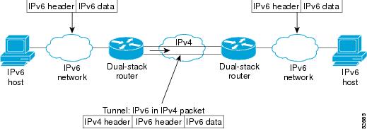
Overlay tunneling encapsulates IPv6 packets in IPv4 packets for delivery across an IPv4 infrastructure (a core network or the Internet (see the figure below). By using overlay tunnels, you can communicate with isolated IPv6 networks without upgrading the IPv4 infrastructure between them. Overlay tunnels can be configured between border routers or between a border router and a host; however, both tunnel endpoints must support both the IPv4 and IPv6 protocol stacks. IPv6 supports the following types of overlay tunneling mechanisms:
- Manual
- Generic routing encapsulation (GRE)
- IPv4-compatible
- 6to4
- Intrasite Automatic Tunnel Addressing Protocol (ISATAP)
Use the table below to help you determine which type of tunnel you want to configure to carry IPv6 packets over an IPv4 network.
| Table 1 | Suggested Usage of Tunnel Types to Carry IPv6 Packets over an IPv4 Network |
|
Tunneling Type |
Suggested Usage |
Usage Notes |
|---|---|---|
|
Manual |
Simple point-to-point tunnels that can be used within a site or between sites |
Can carry IPv6 packets only. |
|
GRE- and IPv4- compatible |
Simple point-to-point tunnels that can be used within a site or between sites |
Can carry IPv6, Connectionless Network Service (CLNS), and many other types of packets. |
|
IPv4- compatible |
Point-to-multipoint tunnels |
Uses the ::/96 prefix. We do not now recommend using this tunnel type. |
|
6to4 |
Point-to-multipoint tunnels that can be used to connect isolated IPv6 sites |
Sites use addresses from the 2002::/16 prefix. |
|
6RD |
IPv6 service is provided to customers over an IPv4 network by using encapsulation of IPv6 in IPv4. |
Prefixes can be from the SP's own address block. |
|
ISATAP |
Point-to-multipoint tunnels that can be used to connect systems within a site |
Sites can use any IPv6 unicast addresses. |
Individual tunnel types are discussed in detail in this document. We recommend that you review and understand the information about the specific tunnel type that you want to implement. When you are familiar with the type of tunnel you need, see the table below for a summary of the tunnel configuration parameters that you may find useful.
| Table 2 | Tunnel Configuration Parameters by Tunneling Type |
|
Tunneling Type |
Tunnel Configuration Parameter |
|||
|---|---|---|---|---|
|
Tunnel Mode |
Tunnel Source |
Tunnel Destination |
Interface Prefix or Address |
|
|
Manual |
ipv6ip |
An IPv4 address, or a reference to an interface on which IPv4 is configured. |
An IPv4 address. |
An IPv6 address. |
|
GRE/IPv4 |
gre ip |
An IPv4 address. |
An IPv6 address. |
|
|
IPv4- compatible |
ipv6ip auto-tunnel |
Not required. These are all point-to-multipoint tunneling types. The IPv4 destination address is calculated, on a per-packet basis, from the IPv6 destination. |
Not required. The interface address is generated as ::tunnel-source/96. |
|
|
6to4 |
ipv6ip 6to4 |
An IPv6 address. The prefix must embed the tunnel source IPv4 address |
||
|
6RD |
ipv6ip 6rd |
An IPv6 address. |
||
|
ISATAP |
ipv6ip isatap |
An IPv6 prefix in modified eui-64 format. The IPv6 address is generated from the prefix and the tunnel source IPv4 address. |
IPv6 Manually Configured Tunnels
A manually configured tunnel is equivalent to a permanent link between two IPv6 domains over an IPv4 backbone. The primary use is for stable connections that require regular secure communication between two edge routers or between an end system and an edge router, or for connection to remote IPv6 networks.
An IPv6 address is manually configured on a tunnel interface, and manually configured IPv4 addresses are assigned to the tunnel source and the tunnel destination. The host or router at each end of a configured tunnel must support both the IPv4 and IPv6 protocol stacks. Manually configured tunnels can be configured between border routers or between a border router and a host.
GRE IPv4 Tunnel Support for IPv6 Traffic
IPv6 traffic can be carried over IPv4 GRE tunnels using the standard GRE tunneling technique that is designed to provide the services necessary to implement any standard point-to-point encapsulation scheme. As in IPv6 manually configured tunnels, GRE tunnels are links between two points, with a separate tunnel for each link. The tunnels are not tied to a specific passenger or transport protocol, but in this case carry IPv6 as the passenger protocol with the GRE as the carrier protocol and IPv4 or IPv6 as the transport protocol.
The primary use of GRE tunnels is for stable connections that require regular secure communication between two edge routers or between an edge router and an end system. The edge routers and the end systems must be dual-stack implementations.
GRE has a protocol field that identifies the passenger protocol. GRE tunnels allow Intermediate System-to-Intermediate System (IS-IS) or IPv6 to be specified as a passenger protocol, which allows both IS-IS and IPv6 traffic to run over the same tunnel. If GRE did not have a protocol field, it would be impossible to distinguish whether the tunnel was carrying IS-IS or IPv6 packets. The GRE protocol field is why it is desirable that you tunnel IS-IS and IPv6 inside GRE.
Automatic 6to4 Tunnels
An automatic 6to4 tunnel allows isolated IPv6 domains to be connected over an IPv4 network to remote IPv6 networks. The key difference between automatic 6to4 tunnels and manually configured tunnels is that the tunnel is not point-to-point; it is point-to-multipoint. In automatic 6to4 tunnels, routers are not configured in pairs because they treat the IPv4 infrastructure as a virtual nonbroadcast multiaccess (NBMA) link. The IPv4 address embedded in the IPv6 address is used to find the other end of the automatic tunnel.
An automatic 6to4 tunnel may be configured on a border router in an isolated IPv6 network, which creates a tunnel on a per-packet basis to a border router in another IPv6 network over an IPv4 infrastructure. The tunnel destination is determined by the IPv4 address of the border router extracted from the IPv6 address that starts with the prefix 2002::/16, where the format is 2002:border-router-IPv4-address ::/48. Following the embedded IPv4 address are 16 bits that can be used to number networks within the site. The border router at each end of a 6to4 tunnel must support both the IPv4 and IPv6 protocol stacks. 6to4 tunnels are configured between border routers or between a border router and a host.
The simplest deployment scenario for 6to4 tunnels is to interconnect multiple IPv6 sites, each of which has at least one connection to a shared IPv4 network. This IPv4 network could be the global Internet or a corporate backbone. The key requirement is that each site have a globally unique IPv4 address; the Cisco software uses this address to construct a globally unique 6to4/48 IPv6 prefix. As with other tunnel mechanisms, appropriate entries in a Domain Name System (DNS) that map between hostnames and IP addresses for both IPv4 and IPv6 allow the applications to choose the required address.
IPv6 Rapid Deployment Tunnels
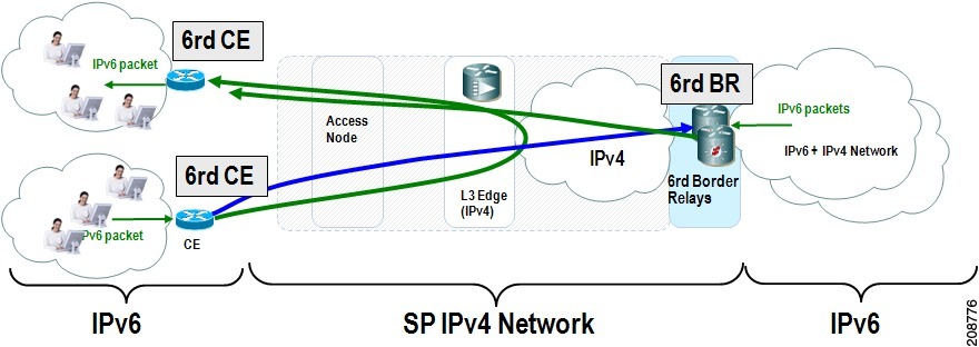
The 6RD feature is an extension of the 6to4 feature. The 6RD feature allows a service provider (SP) to provide a unicast IPv6 service to customers over its IPv4 network by using encapsulation of IPv6 in IPv4.
The main differences between 6RD and 6to4 tunneling are as follows:
- 6RD does not require addresses to have a 2002::/16 prefix; therefore, the prefix can be from the SP's own address block. This function allows the 6RD operational domain to be within the SP network. From the perspective of customer sites and the general IPv6 internet connected to a 6RD-enabled SP network, the IPv6 service provided is equivalent to native IPv6.
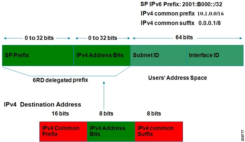
- All 32 bits of the IPv4 destination need not be carried in the IPv6 payload header. The IPv4 destination is obtained from a combination of bits in the payload header and information on the router. Furthermore, the IPv4 address is not at a fixed location in the IPv6 header as it is in 6to4.
The 6RD SP prefix was selected by the SP for the IPv6 deployment shown in the figure below. The 6RD delegated prefix is derived from the SP prefix and the IPv4 address bits, and is used by the CE for hosts within its site.
The figure below shows how 6RD prefix delegation works.
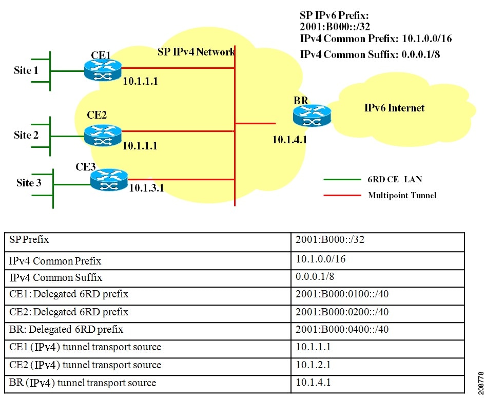
The figure below shows a 6RD prefix delegation topology.
ISATAP Tunnels
ISATAP is an automatic overlay tunneling mechanism that uses the underlying IPv4 network as a NBMA link layer for IPv6. ISATAP is designed for transporting IPv6 packets within a site where a native IPv6 infrastructure is not yet available; for example, when sparse IPv6 hosts are deployed for testing. ISATAP tunnels allow individual IPv4 or IPv6 dual-stack hosts within a site to communicate with other such hosts on the same virtual link, basically creating an IPv6 network using the IPv4 infrastructure.
The ISATAP router provides standard router advertisement network configuration support for the ISATAP site. This feature allows clients to automatically configure themselves as they would do if they were connected to a GigabitEthernet or FastEthernet. It can also be configured to provide connectivity out of the site. ISATAP uses a well-defined IPv6 address format composed of any unicast IPv6 prefix (/64), which can be link local, or global (including 6to4 prefixes), enabling IPv6 routing locally or on the Internet. The IPv4 address is encoded in the last 32 bits of the IPv6 address, enabling automatic IPv6-in-IPv4 tunneling.
Although the ISATAP tunneling mechanism is similar to other automatic tunneling mechanisms, such as IPv6 6to4 tunneling, ISATAP is designed for transporting IPv6 packets within a site, not between sites.
ISATAP uses unicast addresses that include a 64-bit IPv6 prefix and a 64-bit interface identifier. The interface identifier is created in modified EUI-64 format in which the first 32 bits contain the value 000:5EFE to indicate that the address is an IPv6 ISATAP address. The table below describes an ISATAP address format.
| Table 3 | IPv6 ISATAP Address Format |
|
64 Bits |
32 Bits |
32 Bits |
|---|---|---|
|
link local or global IPv6 unicast prefix |
0000:5EFE |
IPv4 address of the ISATAP link |
As shown in the table above, an ISATAP address consists of an IPv6 prefix and the ISATAP interface identifier. This interface identifier includes the IPv4 address of the underlying IPv4 link. The following example shows what an actual ISATAP address would look like if the prefix is 2001:DB8:1234:5678::/64 and the embedded IPv4 address is 10.173.129.8. In the ISATAP address, the IPv4 address is expressed in hexadecimal as 0AAD:8108:
2001:DB8:1234:5678:0000:5EFE:0AAD:8108
How to Implement Tunneling for IPv6
- Configuring Manual IPv6 Tunnels
- Configuring GRE IPv6 Tunnels
- Configuring Automatic 6to4 Tunnels
- Configuring 6RD Tunnels
- Configuring ISATAP Tunnels
- Verifying IPv6 Tunnel Configuration and Operation
Configuring Manual IPv6 Tunnels
With manually configured IPv6 tunnels, an IPv6 address is configured on a tunnel interface, and manually configured IPv4 addresses are assigned to the tunnel source and the tunnel destination. The host or router at each end of a configured tunnel must support both the IPv4 and IPv6 protocol stacks.
DETAILED STEPS
Configuring GRE IPv6 Tunnels
GRE tunnels can be configured to run over an IPv6 network layer and to transport IPv6 packets in IPv6 tunnels and IPv4 packets in IPv6 tunnels.
When GRE IPv6 tunnels are configured, IPv6 addresses are assigned to the tunnel source and the tunnel destination. The tunnel interface can have either IPv4 or IPv6 addresses assigned (this is not shown in the task). The host or router at each end of a configured tunnel must support both the IPv4 and IPv6 protocol stacks.
DETAILED STEPS
| Command or Action | Purpose | |||
|---|---|---|---|---|
Step 1 |
enable
Example: Router> enable |
Enables privileged EXEC mode.
| ||
Step 2 |
configure
terminal
Example: Router# configure terminal |
Enters global configuration mode. | ||
Step 3 |
interface
tunnel
tunnel-number
Example: Router(config)# interface tunnel 0 |
Specifies a tunnel interface and number, and enters interface configuration mode. | ||
Step 4 |
ipv6
address
{ipv6-address / prefix-length | prefix-name sub-bits/prefix-length Example: Router(config-if)# ipv6 address 3ffe:b00:c18:1::3/127 |
Specifies the IPv6 network assigned to the interface and enables IPv6 processing on the interface. | ||
Step 5 |
tunnel
source
{ip-address | ipv6-address | interface-type interface-number} Example: Router(config-if)# tunnel source gigabitethernet 0/0/0 |
Specifies the source IPv4 address or the source interface type and number for the tunnel interface.
| ||
Step 6 |
tunnel
destination
{host-name | ip-address | ipv6-address} Example: Router(config-if)# tunnel destination 2001:DB8:1111:2222::1/64 |
Specifies the destination IPv4 address or hostname for the tunnel interface. | ||
Step 7 |
tunnel
mode
{aurp | cayman | dvmrp | eon | gre| gre multipoint | gre ipv6 | ipip
[decapsulate-any] | iptalk | ipv6 | mpls | nos Example: Router(config-if)# tunnel mode gre ipv6 |
Specifies a GRE IPv6 tunnel.
|
Configuring Automatic 6to4 Tunnels
With 6to4 tunnels, the tunnel destination is determined by the border router IPv4 address, which is concatenated to the prefix 2002::/16 in the format 2002:border-router-IPv4-address ::/48. The border router at each end of a 6to4 tunnel must support both the IPv4 and IPv6 protocol stacks.
 Note | The configuration of only one IPv4-compatible tunnel and one 6to4 IPv6 tunnel is supported on a router. If you choose to configure both of those tunnel types on the same router, we strongly recommend that they do not share the same tunnel source. The reason that a 6to4 tunnel and an IPv4-compatible tunnel cannot share an interface is that both of them are NBMA "point-to-multipoint" access links and only the tunnel source can be used to reorder the packets from a multiplexed packet stream into a single packet stream for an incoming interface. So when a packet with an IPv4 protocol type of 41 arrives on an interface, that packet is mapped to an IPv6 tunnel interface based on the IPv4 address. However, if both the 6to4 tunnel and the IPv4-compatible tunnel share the same source interface, the router is not able to determine the IPv6 tunnel interface to which it should assign the incoming packet. IPv6 manually configured tunnels can share the same source interface because a manual tunnel is a "point-to-point" link, and both the IPv4 source and IPv4 destination of the tunnel are defined. > |
DETAILED STEPS
| Command or Action | Purpose | |||
|---|---|---|---|---|
Step 1 |
enable
Example: Router> enable |
Enables privileged EXEC mode.
| ||
Step 2 |
configure
terminal
Example: Router# configure terminal |
Enters global configuration mode. | ||
Step 3 |
interface
tunnel
tunnel-number
Example: Router(config)# interface tunnel 1 |
Specifies a tunnel interface and number, and enters interface configuration mode. | ||
Step 4 |
ipv6
address
{ipv6-address / prefix-length | prefix-name sub-bits/prefix-length Example: Router(config-if)# ipv6 address 3ffe:b00:c18:1::3/127 |
Specifies the IPv6 network assigned to the interface and enables IPv6 processing on the interface. | ||
Step 5 |
tunnel
source
{ip-address| interface-t ype interface-number} Example: Router(config-if)# tunnel source loopback 1 |
Specifies the source interface type and number for the tunnel interface. | ||
Step 6 |
tunnel
mode
ipv6ip
[6rd | 6to4 | auto-tunnel | isatap Example: Router(config-if)# tunnel mode ipv6ip 6rd |
Configures a static IPv6 tunnel interface.
| ||
Step 7 |
exit
Example: Router(config-if) exit |
Exits interface configuration mode, and enters global configuration mode. | ||
Step 8 |
ipv6
route
[vrf vrf-name] ipv6-prefix / prefix-length{ipv6-address | interface-type interface-number [ipv6-address]} [nexthop-vrf [vrf-name1 | default]] [administrative-distance] [administrative-multicast-distance | unicast | multicast] [next-hop-address] [tag tag] Example: Router(config)# ipv6 route 2002::/16 tunnel 0 |
Configures a static route for the IPv6 6to4 prefix 2002::/16 to the specified tunnel interface.
|
Configuring 6RD Tunnels
DETAILED STEPS
| Command or Action | Purpose | |
|---|---|---|
Step 1 |
enable
Example: Router> enable |
Enables privileged EXEC mode. |
Step 2 |
configure
terminal
Example: Router# configure terminal |
Enters global configuration mode. |
Step 3 |
interface
tunnel
tunnel-number
Example: Router(config)# interface tunnel 1 |
Specifies a tunnel interface and number, and enters interface configuration mode. |
Step 4 |
tunnel
source
{ip-address|
interface-t
ype
interface-number}
Example: Router(config-if)# tunnel source loopback 1 |
Specifies the source interface type and number for the tunnel interface. |
Step 5 |
tunnel
mode
ipv6ip
[6rd |
6to4 |
auto-tunnel |
isatap]
Example: Router(config-if)# tunnel mode ipv6ip 6rd |
Configures a static IPv6 tunnel interface. |
Step 6 |
tunnel
6rd
prefix
ipv6-prefix
/
prefix-length
Example: Router(config-if)# tunnel 6rd prefix 2001:B000::/32 |
Specifies the common IPv6 prefix on IPv6 rapid 6RD tunnels. |
Step 7 |
tunnel
6rd
ipv4
{prefix-length
length} {suffix-length
length}
Example: Router(config-if)# tunnel 6rd ipv4 prefix-length 16 suffix 8 |
Specifies the prefix length and suffix length of the IPv4 transport address common to all the 6RD routers in a domain. |
Configuring ISATAP Tunnels
The tunnel source command used in the configuration of an ISATAP tunnel must point to an interface with an IPv4 address configured. The ISATAP IPv6 address and prefix (or prefixes) advertised are configured as for a native IPv6 interface. The IPv6 tunnel interface must be configured with a modified EUI-64 address because the last 32 bits in the interface identifier are constructed using the IPv4 tunnel source address.
DETAILED STEPS
| Command or Action | Purpose | |||
|---|---|---|---|---|
Step 1 |
enable
Example: Router> enable |
Enables privileged EXEC mode.
| ||
Step 2 |
configure
terminal
Example: Router# configure terminal |
Enters global configuration mode. | ||
Step 3 |
interface
tunnel
tunnel-number
Example: Router(config)# interface tunnel 1 |
Specifies a tunnel interface and number, and enters interface configuration mode. | ||
Step 4 |
ipv6
address
{ipv6-address / prefix-length | prefix-name sub-bits/prefix-length Example: Router(config-if)# ipv6 address 2001:DB8:6301::/64 eui-64 |
Specifies the IPv6 address assigned to the interface and enables IPv6 processing on the interface. | ||
Step 5 |
no
ipv6
nd
ra
suppress
Example: Router(config-if)# no ipv6 nd ra suppress |
Sending of IPv6 router advertisements is disabled by default on tunnel interfaces. This command reenables the sending of IPv6 router advertisements to allow client autoconfiguration. | ||
Step 6 |
tunnel
source
{ip-address| interface-type interface-number} Example: Router(config-if)# tunnel source gigabitethernet 1/0/1 |
Specifies the source interface type and number for the tunnel interface.
| ||
Step 7 |
tunnel
mode
ipv6ip
[6rd | 6to4 | auto-tunnel | isatap Example: Router(config-if)# tunnel mode ipv6ip isatap |
Specifies an IPv6 overlay tunnel using a ISATAP address.
|
Verifying IPv6 Tunnel Configuration and Operation
DETAILED STEPS
| Command or Action | Purpose | |||
|---|---|---|---|---|
Step 1 |
enable
Example: Router> enable |
Enables privileged EXEC mode.
| ||
Step 2 |
show
interfaces
tunnel
number
[accounting] Example: Router# show interfaces tunnel 0 |
(Optional) Displays tunnel interface information.
| ||
Step 3 |
ping
[protocol] destination Example: Router# ping 10.0.0.1 |
(Optional) Diagnoses basic network connectivity. | ||
Step 4 |
show
ip
route
[address[mask]] Example: Router# show ip route 10.0.0.2 |
(Optional) Displays the current state of the routing table.
| ||
Step 5 |
show
tunnel
6rd
[interface-type interface-number Example: Router# show tunnel 6rd tunnel 1 |
Displays 6RD information about a tunnel. | ||
Step 6 |
show
tunnel
6rd
destination
ipv6-prefix
tunnel-interface
interface-number
Example: Router# show tunnel 6rd destination 2001:B000:300:: tunnel 1 |
Translates and displays a 6RD prefix to the corresponding IPv4 destination. | ||
Step 7 |
show
tunnel
6rd
prefix
ipv4-destination
tunnel-interface
interface-number
Example: Router# show tunnel 6rd prefix 10.1.4.1 tunnel 1 |
Translates and displays an IPv4 destination address to the corresponding 6RD prefix. |
Examples
- Sample Output from the show interfaces tunnel Command
- Sample Output from the ping Command When Checking the Local Endpoint
- Sample Output from the show ip route Command
- Sample Output from the ping Command When Checking the Remote Endpoint
Sample Output from the show interfaces tunnel Command
This example uses a generic example suitable for both IPv6 manually configured tunnels and IPv6 over IPv4 GRE tunnels. In the example, two routers are configured to be endpoints of a tunnel. Router A has GigabitEthernet interface 0/0/0 configured as tunnel interface 0 with an IPv4 address of 10.0.0.1 and an IPv6 prefix of 2001:DB8:1111:2222::1/64. Router B has GigabitEthernet interface 0/0/0 configured as tunnel interface 1 with an IPv4 address of 10.0.0.2 and an IPv6 prefix of 2001:DB8:1111:2222::2/64. To verify that the tunnel source and destination addresses are configured, use the show interfaces tunnel command on Router A.
RouterA# show interfaces tunnel 0
Tunnel0 is up, line protocol is up
  Hardware is Tunnel
  MTU 1514 bytes, BW 9 Kbit, DLY 500000 usec,
     reliability 255/255, txload 1/255, rxload 1/255
  Encapsulation TUNNEL, loopback not set
  Keepalive not set
  Tunnel source 10.0.0.1 (GigabitEthernet0/0/0), destination 10.0.0.2, fastswitch TTL 255
  Tunnel protocol/transport GRE/IP, key disabled, sequencing disabled
  Tunnel TTL 255
  Checksumming of packets disabled,  fast tunneling enabled
  Last input 00:00:14, output 00:00:04, output hang never
  Last clearing of "show interface" counters never
  Input queue: 0/75/0/0 (size/max/drops/flushes); Total output drops: 0
  Queueing strategy: fifo
  Output queue :0/0 (size/max)
  5 minute input rate 0 bits/sec, 0 packets/sec
  5 minute output rate 0 bits/sec, 0 packets/sec
     4 packets input, 352 bytes, 0 no buffer
     Received 0 broadcasts, 0 runts, 0 giants, 0 throttles
     0 input errors, 0 CRC, 0 frame, 0 overrun, 0 ignored, 0 abort
     8 packets output, 704 bytes, 0 underruns
     0 output errors, 0 collisions, 0 interface resets
     0 output buffer failures, 0 output buffers swapped out
Sample Output from the ping Command When Checking the Local Endpoint
To check that the local endpoint is configured and working, use the ping command on Router A:
RouterA# ping 2001:DB8:1111:2222::2
Type escape sequence to abort.
Sending 5, 100-byte ICMP Echos to 2001:DB8:1111:2222::2, timeout is 2 seconds:
!!!!!
Success rate is 100 percent (5/5), round-trip min/avg/max = 20/20/20 ms
Sample Output from the show ip route Command
To check that a route exists to the remote endpoint address, use the show ip route command:
RouterA# show ip route 10.0.0.2
Routing entry for 10.0.0.0/24
  Known via "connected", distance 0, metric 0 (connected, via interface)
  Routing Descriptor Blocks:
  * directly connected, via GigabitEthernet0/0/0
      Route metric is 0, traffic share count is 1
Sample Output from the ping Command When Checking the Remote Endpoint
To check that the remote endpoint address is reachable, use the ping command on Router A.
Note | The remote endpoint address may not be reachable using the ping command because of filtering, but the tunnel traffic may still reach its destination. |
RouterA# ping 10.0.0.2
Type escape sequence to abort.
Sending 5, 100-byte ICMP Echos to 10.0.0.2, timeout is 2 seconds:
!!!!!
Success rate is 100 percent (5/5), round-trip min/avg/max = 20/21/28 ms
To check that the remote IPv6 tunnel endpoint is reachable, use the ping command again on Router A. The same note on filtering also applies to this example.
RouterA# ping 1::2
Type escape sequence to abort.
Sending 5, 100-byte ICMP Echos to 1::2, timeout is 2 seconds:
!!!!!
Success rate is 100 percent (5/5), round-trip min/avg/max = 20/20/20 ms
These steps may be repeated at the other endpoint of the tunnel.
Configuration Examples for Implementing Tunneling for IPv6
- Example: Configuring Manual IPv6 Tunnels
- Example Configuring GRE Tunnels
- Example: Configuring 6to4 Tunnels
- Example: Configuring 6RD Tunnels
- Example: Configuring IPv4-Compatible IPv6 Tunnels
- Example: Configuring ISATAP Tunnels
Example: Configuring Manual IPv6 Tunnels
The following example configures a manual IPv6 tunnel between router A and router B. In the example, tunnel interface 0 for both router A and router B is manually configured with a global IPv6 address. The tunnel source and destination addresses are also manually configured.
Example Configuring GRE Tunnels
The following example configures a GRE tunnel running both IS-IS and IPv6 traffic between router A and router B:
Router A Configuration
ipv6 unicast-routing
clns routing
!
interface tunnel 0
 no ip address
 ipv6 address 2001:DB8:1111:2222::1/64
 ipv6 router isis
 tunnel source GigabitEthernet 0/0/0
 tunnel destination 10.0.0.2
 tunnel mode gre ipv6
!
interface GigabitEthernet0/0/0
 ip address 10.0.0.1 255.255.255.0
!
router isis
 net 49.0000.0000.000a.00
Router B Configuration
ipv6 unicast-routing
clns routing
!
interface tunnel 0
 no ip address
 ipv6 address 2001:DB8:1111:2222::2/64
 ipv6 router isis
 tunnel source GigabitEthernet 0/0/0
 tunnel destination 10.0.0.1
 tunnel mode gre ipv6
!
interface GigabitEthernet0/0/0
 ip address 10.0.0.2 255.255.255.0
!
router isis
 net 49.0000.0000.000b.00
 address-family ipv6
 redistribute static
 exit-address-family
Example: Tunnel Destination Address for IPv6 Tunnel
Router(config
)
#
interface Tunnel0
Router(config
-if)
#
ipv6 address 2001:1:1::1/48
Router(config
-if)
#
tunnel source GigabitEthernet 0/0/0
Router(config
-if)
#
tunnel destination 10.0.0.2
Router(config
-if)
#
tunnel mode gre ipv6
Router(config
-if)
#
exit
!
Router(config
)
#
interface GigabitEthernet0/0/0
Router(config
-if)
#
ip address 10.0.0.1 255.255.255.0
Router(config
-if)
#
exit
!
Router(config
)
#
ipv6 unicast-routing
Router(config
)
#
router isis

Router(config
)
#
net 49.0000.0000.000a.00
Example: Configuring 6to4 Tunnels
The following example configures a 6to4 tunnel on a border router in an isolated IPv6 network. The IPv4 address is 192.168.99.1, which translates to the IPv6 prefix of 2002:c0a8:6301::/48. The IPv6 prefix is subnetted into 2002:c0a8:6301::/64 for the tunnel interface: 2002:c0a8:6301:1::/64 for the first IPv6 network, and 2002:c0a8:6301:2::/64 for the second IPv6 network. The static route ensures that any other traffic for the IPv6 prefix 2002::/16 is directed to tunnel interface 0 for automatic tunneling.
interface GigabitEthernet0/0/0
 description IPv4 uplink
 ip address 192.168.99.1 255.255.255.0
!
interface GigabitEthernet1/0/0
 description IPv6 local network 1
 ipv6 address 2002:c0a8:6301:1::1/64
!
interface GigabitEthernet2/0/0
 description IPv6 local network 2
 ipv6 address 2002:c0a8:6301:2::1/64
!
interface Tunnel0
 description IPv6 uplink
 no ip address
 ipv6 address 2002:c0a8:6301::1/64
 tunnel source GigabitEthernet0/0/0
 tunnel mode ipv6ip 6to4
!
ipv6 route 2002::/16 tunnel 0
Example: Configuring 6RD Tunnels
The following example shows the running configuration of a 6RD tunnel and the corresponding output of the show tunnel 6rd command:
interface Tunnel1
 ipv6 address 2001:B000:100::1/32
 tunnel source loopback 1
 tunnel mode ipv6ip 6rd
 tunnel 6rd prefix 2001:B000::/32
 tunnel 6rd ipv4 prefix-len 16 suffix-len 8
end
Router# show tunnel 6rd tunnel 1
Interface Tunnel1:
  Tunnel Source: 10.1.1.1
  6RD: Operational, V6 Prefix: 2001:B000::/32
  V4 Common Prefix Length: 16, Value: 10.1.0.0
  V4 Common Suffix Length: 8, Value: 0.0.0.1
Example: Configuring IPv4-Compatible IPv6 Tunnels
The following example configures an IPv4-compatible IPv6 tunnel that allows Border Gateway Protocol (BGP) to run between a number of routers without having to configure a mesh of manual tunnels. Each router has a single IPv4-compatible tunnel, and multiple BGP sessions can run over each tunnel, one to each neighbor. GigabitEthernet interface 0/0/0 is used as the tunnel source. The tunnel destination is automatically determined by the IPv4 address in the low-order 32 bits of an IPv4-compatible IPv6 address. Specifically, the IPv6 prefix 0:0:0:0:0:0 is concatenated to an IPv4 address (in the format 0:0:0:0:0:0:A.B.C.D or ::A.B.C.D) to create the IPv4-compatible IPv6 address. GigabitEthernet interface 0/0/0 is configured with a global IPv6 address and an IPv4 address (the interface supports both the IPv6 and IPv4 protocol stacks).
Multiprotocol BGP is used in the example to exchange IPv6 reachability information with the peer 10.67.0.2. The IPv4 address of GigabitEthernet interface 0/0/0 is used in the low-order 32 bits of an IPv4-compatible IPv6 address and is also used as the next-hop attribute. Using an IPv4-compatible IPv6 address for the BGP neighbor allows the IPv6 BGP session to be automatically transported over an IPv4-compatible tunnel.
interface tunnel 0
 tunnel source GigabitEthernet 0/0/0
 tunnel mode ipv6ip auto-tunnel
interface Gigabitethernet 0/0/0
 ip address 10.27.0.1 255.255.255.0
 ipv6 address 3000:2222::1/64
router bgp 65000
 no synchronization
 no bgp default ipv4-unicast
neighbor ::10.67.0.2 remote-as 65002
address-family ipv6
 neighbor ::10.67.0.2 activate
 neighbor ::10.67.0.2 next-hop-self
 network 2001:2222:d00d:b10b::/64
Example: Configuring ISATAP Tunnels
The following example shows the tunnel source defined on GigabitEthernet 0/0/0 and the tunnel mode command used to configure the ISATAP tunnel. Router advertisements are enabled to allow client autoconfiguration.
ipv6 unicast-routing
interface tunnel 1
 tunnel source Gigabitethernet 0/0/0
 tunnel mode ipv6ip isatap
 ipv6 address 2001:DB8::/64 eui-64
 no ipv6 nd ra suppress
 exit
Additional References
Related Documents
| Related Topic | Document Title |
|---|---|
|
IPv6 addressing and connectivity |
IPv6 Configuration Guide |
|
Cisco IOS commands |
|
|
IPv6 commands |
|
|
Cisco IOS IPv6 features |
IPv6 Feature Mapping |
Technical Assistance
| Description | Link |
|---|---|
|
The Cisco Support and Documentation website provides online resources to download documentation, software, and tools. Use these resources to install and configure the software and to troubleshoot and resolve technical issues with Cisco products and technologies. Access to most tools on the Cisco Support and Documentation website requires a Cisco.com user ID and password. |
Feature Information for Implementing Tunneling for IPv6
The following table provides release information about the feature or features described in this module. This table lists only the software release that introduced support for a given feature in a given software release train. Unless noted otherwise, subsequent releases of that software release train also support that feature.
Use Cisco Feature Navigator to find information about platform support and Cisco software image support. To access Cisco Feature Navigator, go to www.cisco.com/go/cfn. An account on Cisco.com is not required.
| Table 4 | Feature Information for Implementing Tunneling for IPv6 |
|
Feature Name |
Releases |
Feature Information |
|---|---|---|
|
IPv6 Tunneling--6RD IPv6 Rapid Deployment |
Cisco IOS XE Release 3.1S |
The 6RD feature allows a service provider to provide a unicast IPv6 service to customers over its IPv4 network by using encapsulation of IPv6 in IPv4. |
|
IPv6 Tunneling--Automatic 6to4 Tunnels |
Cisco IOS XE Release 2.1 |
An automatic 6to4 tunnel allows isolated IPv6 domains to be connected over an IPv4 network to remote IPv6 networks. |
|
IPv6 Tunneling--Automatic IPv4-Compatible Tunnels |
Cisco IOS XE Release 2.1 |
Automatic IPv4-compatible tunnels use IPv4-compatible IPv6 addresses. |
|
IPv6 Tunneling--IP over IPv6 GRE Tunnels |
Cisco IOS XE Release 2.4 |
GRE tunnels are links between two points, with a separate tunnel for each link. |
|
IPv6 Tunneling--IPv4 over IPv6 Tunnels |
Cisco IOS XE Release 2.1 |
IPv6 supports this feature |
|
IPv6 Tunneling--IPv6 over IPv4 GRE Tunnels |
Cisco IOS XE Release 2.1 |
GRE tunnels are links between two points, with a separate tunnel for each link. The tunnels are not tied to a specific passenger or transport protocol, but in this case carry IPv6 as the passenger protocol with the GRE as the carrier protocol and IPv4 or IPv6 as the transport protocol. |
|
IPv6 Tunneling--ISATAP Tunnel Support |
Cisco IOS XE Release 2.1 Cisco IOS XE Release 3.3SG |
ISATAP is an automatic overlay tunneling mechanism that uses the underlying IPv4 network as a NBMA link layer for IPv6. |
|
IPv6 Tunneling--Manually Configured IPv6 over IPv4 Tunnels |
Cisco IOS XE Release 2.1 |
A manually configured tunnel is equivalent to a permanent link between two IPv6 domains over an IPv4 backbone. |
|
IPv6 Switching: CEFv6 Switched Configured IPv6 over IPv4 Tunnels |
Cisco IOS XE Release 3.3SG |
Supports CEF switching of IPv6 auto 6to4 tunnels. |
Cisco and the Cisco logo are trademarks or registered trademarks of Cisco and/or its affiliates in the U.S. and other countries. To view a list of Cisco trademarks, go to this URL: www.cisco.com/go/trademarks. Third-party trademarks mentioned are the property of their respective owners. The use of the word partner does not imply a partnership relationship between Cisco and any other company. (1110R)
Any Internet Protocol (IP) addresses and phone numbers used in this document are not intended to be actual addresses and phone numbers. Any examples, command display output, network topology diagrams, and other figures included in the document are shown for illustrative purposes only. Any use of actual IP addresses or phone numbers in illustrative content is unintentional and coincidental.