Feedback
Table Of Contents
Cisco IPICS Infrastructure Considerations
Calculating Codec Bandwidth Use
cRTP, Variable-Payload Sizes and Aggressive VAD
Adjustable Byte Size of the Voice Payload
Aggressive Voice Activity Detection
QoS with Point-to-Point Connections
Guidelines for Using IP Multicast Addresses with Cisco IPICS
Securing the Cisco IPICS Infrastructure
Firewalls and Access Control Lists
Other Security Recommendations
Cisco IPICS Network Management System
Cisco IPICS Infrastructure Considerations
This chapter contains information about infrastructure issues that you must be aware of when you deploy Cisco IPICS.
To access related documentation, refer to the following URLs:
•
IP multicast:
http://www.cisco.com/univercd/cc/td/doc/product/software/ios124/124cg/himc_c/index.htm
•
http://www.cisco.com/univercd/cc/td/doc/product/software/ios124/124cg/hqos_c/index.htm
•
http://www.cisco.com/univercd/cc/td/doc/product/software/ios124/124tcg/vcl.htm
•
http://www.cisco.com/en/US/netsol/ns340/ns394/ns165/ns70/networking_solutions_
package.htmlThis chapter includes these topics:
•
•
WAN Considerations
To ensure the successful deployment of Cisco IPICS over a WAN, you must carefully plan, design, and implement the WAN. Make sure to consider the following factors:
•
•
•
•
•
•
Multicast Routing
Cisco supports the Protocol Independent Multicast (PIM) routing protocol for both sparse mode (SM) and dense mode (DM). However, because of its periodic broadcast and prune mechanism, DM PIM is not recommended for production networks.
Cisco recommends using bidirectional PIM for Cisco IPICS. Bidirectional PIM is an extension of the PIM suite of protocols that implements shared sparse trees with bidirectional data flow. In contrast to PIM-sparse mode, bidirectional PIM avoids keeping source-specific states in a router and allows trees to scale to an arbitrary number of sources while requiring only minimal additional overhead.
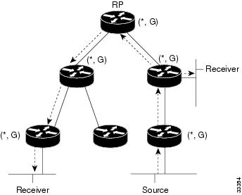
The shared trees that are created in PIM SM are unidirectional. Therefore, a source tree must be created to bring a data stream to the rendezvous point (RP), which is the root of the shared tree. Then the data can be forwarded down the branches to receivers. In the unidirectional mode, source data cannot flow up the shared tree toward the RP.
In bidirectional mode, traffic is routed only along a bidirectional shared tree that is rooted at the RP for the group. In bidirectional PIM, the IP address of the RP acts as the key to having all routers establish a loop-free spanning tree topology that is rooted in that IP address. The IP address does not need to be a router. It can be any unassigned IP address on a network that can be reached throughout the PIM domain.
Figure 3-1 shows bidirectional shared tree. In this example, data from the source can flow up the shared tree (*, G) toward the RP and then down the shared tree to the receiver. There is no registration process so source tree (S, G) is created.
Figure 3-1 Bidirectional Shared Tree
Bidirectional PIM is derived from the mechanisms of PIM SM and has many of the same shared tree operations. Bidirectional PIM also has unconditional forwarding of source traffic toward the RP upstream on the shared tree, but no registering process for sources, as provided by PIM SM. These modifications are necessary and sufficient to allow forwarding of traffic to all routers based only on the (*, G) multicast routing entries. Bidirectional PIM eliminates any source-specific state and allows scaling to an arbitrary number of sources.
In a Cisco IPICS deployment, bidirectional PIM provides scalability in the following ways:
•
•
Bandwidth Planning
To ensure sufficient bandwidth for the operation of Cisco IPICS, there are several issues to consider as you plan and deploy your network. These issues include:
•
•
In addition, you should consider the guaranteed bandwidth that is available on the VoIP network. Make sure to take into account both LAN and WAN bandwidth and to consider factors such as Frame Relay, Committed Information Rate (CIR) or Asynchronous Transfer Mode Peak Cell Rate (ATM PCR), Sustained Cell Rate, and burst. For additional information see the "Quality of Service" section.
Codecs
Cisco IPICS uses either the G.711 or G.729a codec. This section provides the following information about codecs:
•
Choosing a Codec
When choosing a codec for Cisco IPICS, consider the issues that are described in Table 3-1.
Calculating Codec Bandwidth Use
This section explains how to calculate bandwidth use for codecs.
By default, Cisco IOS sends all VoIP traffic (that is, media traffic that uses RTP) at a rate of 50 packets/second. In addition to the voice sample, each packets includes an IP, UDP, and Real-time Transport Protocol (RTP) header, which adds 40 bytes to the packet. Layer 2 headers (such as Frame Relay, Point-to-Point Protocol, Ethernet) also add bytes to each packet.
The amount of bandwidth that is consumed by a VoIP call depends on the codec that is used, and can be calculated as follows. Make sure to also add the appropriate number of bytes for the Layer 2 header to determine the actual bandwidth that is consumed.
G.729a (8K CS-ACELP)
50 packets/second
20ms samples / packet = 20 bytes
AP/UDP/RTP headers/packet = 40 bytes
(20 bytes [payload] + 40 bytes [headers]) * 50 packets/second = 3,000 bytes * 8 bits = 24 kbps
G.711 (64K PCM)
50 packets/second
20ms samples / packet = 160 bytes
AP/UDP/RTP headers/packet = 40 bytes
(160 bytes [payload] + 40 bytes [headers]) * 50 packets/second = 10,000 bytes * 8 bits = 80 kbps
Table 3-2 shows sample bandwidth consumption. In this table,
•
•
•
•
•
According to RFC 1889 (RTP: A Transport Protocol for Real-Time Applications), the RTCP traffic for any RTP stream is limited to a maximum of 5% of the voice stream (RTP + RTCP). This limitation applies to the three streams that participate in a Cisco IPICS session. Therefore, the RTCP Bandwidth per Cisco IPICS Session is calculated by multiplying the bandwidth per voice stream by 3 and then multiplying that product by 0.05.
When you design a Cisco IPICS network within a campus network, you should not run into any bandwidth-related issues because IP multicast is used to replicate a voice stream and map it to an IP multicast group, in which RMS resources are not used. When remote users connect over a WAN that is not multicast enabled, the RMS converts a multicast stream to an IP unicast stream, which conserves bandwidth on the WAN. When the IP unicast voice stream arrives at the RMO, the RMS converts the IP unicast stream to an multicast stream. When the voice streams traverse a WAN, the RMS resources are used. In this scenario the RMS gateways are configured for M1:U12:M2 unicast connection trunks. For additional information, see the "M1:U12:M2 Connection Trunks" section.
As an example of the bandwidth affect of PMCs that are deployed across a WAN, assume that 40 PMC users are communicating over a WAN. Although each multicast voice stream is converted to an IP unicast voice stream so that it can traverse as a IP unicast stream, this scenario could still require substantial bandwidth, depending on the number of channels and the codec type that is used by each PMC. In this example, the bandwidth requirements are as follows:
G.729a
40 PMC Users x 8 Channels per User x (24 kbps + 3.6kbps) = 8.832 kbps
G.711
40 PMC Users x 8 Channels per User x (80 kbps + 12 kbps) = 29,440 kbps
cRTP, Variable-Payload Sizes and Aggressive VAD
There are several methods that you can use to modify the bandwidth that a call consumes. These methods include the following:
•
•
RTP Header Compression
As described in the "Codecs" section, IP/UDP/RTP headers add 40 bytes to each packet. However, a packet header is typically unchanged throughout a call. You can enable cRTP for VoIP calls, which reduces the size of IP/UDP/RTP headers to 2 to 4 bytes per packet.
For detailed information about cRTP, refer to Understanding Compression (Including cRTP) and Quality of Service, which is available at this URL:
http://www.cisco.com/en/US/tech/tk543/tk762/technologies_tech_note09186a0080108e2c
.shtmlAdjustable Byte Size of the Voice Payload
You can control the size of the voice payload that is included in each Cisco IPICS voice packet. To do so, use the bytes parameter in a VoIP dial peer. For example:
dial-peer voice 1 voipdestination-pattern 4085551234codec g729r8 bytes 40session protocol multicastsession target ipv4:239.192.1.1:21000Modifying the number of bytes per packet changes the number of packets that are sent per second. You can calculate the number of packets that are sent per second as shown in these examples:
G.729a codec, with default 20byte payload/packet
Codec rate: 8,000 bits/second * 8 bits = 1,000 byes/second
Sampling interval: 10 ms
Default payload size: 20 bytes/packet (2 samples/packet)
1,000 bytes/sec/20bytes/pkt = 50 packets/sec
G.729a codec, with 40 bytes defined in VoIP dial-peer
Codec rate: 8,000 bits/second * 8 bits = 1,000 byes/second
Sampling interval: 10 ms
Payload size: 40 bytes/packet
1,000 bytes/sec/40 bytes/pkt = 25 packets/sec
Note
Aggressive Voice Activity Detection
Voice Activation Detection (VAD) is a mechanism that allows a digital signal processor (DSP) to dynamically sense pauses in conversation. When such pauses occur, no VoIP packets are sent into the network. VAD can reduce the amount of bandwidth used for a VoIP call by up to 50%.
Although VAD conserves bandwidth in VoIP, it disrupts and marginalizes Cisco IPICS signaling, which is used for LMR and PTT packet streams. Be aware of this issue if you use VAD in a Cisco IPICS deployment.
When configuring LMR gateway ports, VAD should not be used if the radio supports Carrier Operated Relay (COR) or Carrier Operated Squelch (COS). Radios that support COR/COS signaling can provide hardwired signaling to the LMR port to start generating packets. Using COR/COS gating is an efficient way to control the audio input and to avoid the possibility of dropping short burst of voice data that may fall below the VAD activation values.
Each voice port has different environmental noises and different users, which can cause a wide variation in noise and speech levels. Conventional VAD can handle these variations, but it is designed for unicast. Conventional VAD usually prefers over-detection to under-detection, as good voice quality is typically given precedence over bandwidth conservation. But in a multicast environment, over-detection and under-detection are not desirable because they degrade voice quality.
Aggressive VAD can be used in a multicast environment to avoid over-detection. With aggressive VAD, when a DSP detects signals with an unknown signal-to-noise ratio (SNR), the DSP does not transmit spurious packets. With conventional VAD, when the DSP detects signals with an unknown SNR, the DSP continues to transmit packets, which can cause unwanted traffic to take over all slots that are available for voice streams.
You can enable aggressive VAD by enabling the vad aggressive configuration setting under a dial peer as follows:
dial-peer voice 10 voipdestination-pattern 111session protocol multicastsession target ipv4:239.192.1.1:21000vad aggressiveMixing Voice Streams
As described in the "Virtual Talk Groups" section, the DSPs in a Cisco IPICS deployment can mix up to three voice streams. However, the DSPs do not perform a summation function. For example, if three G.729a streams (24K each with headers) are received by a router or gateway, the mixed stream would consume 72K bandwidth. Even though each user in a VTG or a channel in the VTG receives a single mixed audio stream, the DSP does not send a single 24 K stream.
It is important to consider this issue when you plan bandwidth in a Cisco IPICS network. It is especially important when planning WAN bandwidth, which can be more expensive and less available then LAN bandwidth.
Because the Cisco Hoot `n' Holler feature mixes up to three voice streams at a time, you do not need to provision voice bandwidth for more than three times the per-call bandwidth for each WAN site that includes routers with the Cisco Hoot `n' Holler feature.
Note
Quality of Service
There are several QoS features that should be enabled so that a Cisco IPICS deployment can deliver toll-quality VoIP QoS. This section provides an overview of these feature for Point-to-Point Protocol (PPP) and Frame Relay WAN topologies and for deployments on LAN media.
This section includes these topics:
•
QoS Overview
QoS provides consistent voice latency and minimal packet loss. The following recommendations apply to QoS in campus LAN and WAN environments:
•
•
As you design a VoIP network to deploy real-time applications such as Cisco IPICS, consider the following issues, which can affect voice quality:
•
•
•
•
•
If network are designed and built to provide low delay, limited jitter, and limited packet loss, real-time applications such as Cisco IPICS solution can be successful.
IOS Queuing Techniques
Cisco IOS provides a wide variety of QoS features. The following features are particularly useful for a Cisco IPICS deployment:
For more detailed documentation about IP RTP Priority, refer to the "Congestion Management Overview" chapter in Cisco IOS Quality of Service Solutions Configuration Guide, which is available at this URL:
http://www.cisco.com/univercd/cc/td/doc/product/software/ios122/122cgcr
IP RTP Priority
IP RTP Priority can be applied to point-to-point links and to Frame Relay PVCs. It allows you to provision a fixed amount of bandwidth (in Kb) that is always available for Cisco IPICS packets. If there are no Cisco IPICS packets present in the network (that is, nobody is speaking), the bandwidth is available to other data applications. This predefined amount of bandwidth is serviced as a strict priority-queue within the overall structure of Weighted-Fair Queuing (WFQ). The entrance criteria to this priority queue is a range of UDP ports that are used by Cisco IPICS to send IP packets.
Cisco IPICS uses the UDP port that is selected on the VoIP dial peer, and the next sequential port. The ports can range from 21000 through 65534. The first port must be an even number within this range.
The following example shows the UDP port (24100) defined in the VoIP dial-peer, so the range for the IP RTP Priority is 24100-24101:
dial-peer voice 1 voipdestination-pattern 1111session protocol multicastcodec g711ulawsession target ipv4:239.10.0.100:24100!interface serial 0/0ip address 10.1.1.1ip rtp priority 24100 2 64Low Latency Queuing
Low-Latency Queuing (LLQ) applies to point-to-point links and to Frame Relay PVCs. LLQ creates a strict priority queue, as does IP RTP Priority, but LLQ applies the strict priority queue as a service-class within Class-Based Weighted Fair Queueing (CBWFQ). The functionality of fixed allocation but dynamic usage is again similar to IP RTP Priority.
A primary difference between IP RTP Priority and LLQ is that LLQ allows the use of access control lists (ACLs) as the entrance criteria to the priority queue. This capability provides you with flexibility in determining what types of traffic are allowed into the priority queue.
The following example shows how LLQ is used to prioritize Cisco IPICS traffic:
access-list102 permit udp host 10.1.1.1 host 239.10.0.100 range 24100 24101!class-map voicematch access-group 102!policy-map policy1class voicepriority 50!multilink virtual-template 1!interface virtual-template 1ip address 172.17.254.161 255.255.255.248no ip directed-broadcastno ip mroute-cacheservice-policy output policy1ppp multilinkppp multilink fragment-delay 20ppp multilink interleave!interface serial 2/0bandwidth 256no ip addressno ip directed-broadcastencapsulation pppno fair-queueclockrate 256000ppp multilinkmultilink-group 1QoS with Frame Relay
If you deploy Cisco IPICS in a Frame Relay network, be aware that Frame Relay does not inherently provide QoS. Frame Relay is a best-effort service that expects upper-layer applications to handle retransmissions that occur because of packet loss in the Frame Relay cloud.
Frame Relay typically provides the following parameters:
•
•
To offer the QoS over Frame service, carriers use a technique called over-provisioning bandwidth, in which they sell more bandwidth then they can provide at a particular time. This technique works because not all Frame Relay customers require all available bandwidth at one time.
Some Frame Relay carriers also guarantee a Frame Relay network that is always available and that will not drop any customer packets.
A Frame Relay carrier employs a variety of methods to offer a CIR + Burst service, including the following:
•
•
Table 3-3 summarizes key recommendations when deploying Cisco IPICS on a network with Frame Relay.
Example
Consider a Cisco IPICS Frame Relay network with the following characteristics:
•
•
•
•
Because the broadcast queue is only 40 packets deep by default and Cisco IPICS components (PMC, Cisco Unified IP Phone, RMS) transmits packets at 50 packets/second, the broadcast-queue must be set to prevent voice packets from dropping and to maintain voice quality. The recommended setting for the broadcast-queue is 64 8000 25 (64 queue size, 8,000 bytes per second (64,000 bps), and 25 packets per second).
Frame Relay Broadcast Queue
Broadcast queue is a feature that is used in medium and large IP or IPX networks where routing and service access point (SAP) broadcasts must flow across a Frame Relay network. The broadcast queue is managed independently of the normal interface queue, has its own buffers, and has a configurable size and data rate.
To enable broadcast queue, use this interface command:
frame-relay broadcast-queue size byte-rate packet-rate
A broadcast queue is given a maximum transmission rate (throughput) limit, which is measured in bytes per second and packets per second. The queue is serviced to ensure that only this maximum rate is provided. Because the broadcast queue has priority when transmitting at a rate below the configured maximum, it has a guaranteed minimum bandwidth allocation. The two transmission rate limits are intended to avoid flooding the interface with broadcasts. The actual limit in any second is the first rate limit that is reached. Given the transmission rate restriction, additional buffering is required to store broadcast packets.
The broadcast queue can be configured to store a large number of broadcast packets. You should set the queue size to a value that avoids loss of broadcast routing update packets. The exact size depends on the protocol being used and the number of packets required for each update. To be safe, the queue size should be set so that one complete routing update from each protocol and for each data-link connection identifier (DLCI) can be stored. As a general rule, start with 20 packets per DLCI. The byte rate should be less than both of the following:
•
•
The packet rate is not critical if the byte rate is set conservatively. In general, the packet rate should be set assuming 250-byte packets. The frame-relay broadcast-queue command defaults are as follows:
•
•
•
The following configuration is an example of a Frame Relay connection with an ear and mouth (E&M) port:
Router-1 (Hub Router)hostname FR-1!ip multicast-routing!voice class permanent 1signal timing oos timeout disabledsignal keepalive disabledsignal sequence oos no-action!interface Vif1ip address 1.1.1.1 255.255.255.0ip pim sparse-dense-mode!router ripnetwork 1.1.1.0network 5.5.5.0network 5.5.6.0!interface Serial0/0no frame-relay broadcast-queueencapsulation frame-relayframe-relay traffic-shapingframe-relay broadcast-queue 64 8000 250!interface Serial0/0.1 point-to-pointip address 5.5.5.1 255.255.255.0ip pim sparse-dense-modeframe-relay class ipicsframe-relay interface-dlci 100frame-relay ip rtp header-compression!interface Serial0/0.1 point-to-pointip address 5.5.6.1 255.255.255.0ip pim sparse-dense-modeframe-relay class ipicsframe-relay interface-dlci 100frame-relay ip rtp header-compression!map-class frame-relay ipicsframe-relay cir 128000frame-relay bc 1280frame-relay mincir 128000no frame-relay adaptive-shapingframe-relay fair-queueframe-relay fragment 160frame-relay ip rtp priority 16384 16384 128!voice-port 1/0/0connection trunk 111operation 4-wire!dial-peer voice 1 voipdestination-pattern 111voice class permanent 1session protocol multicastsession target ipv4:239.111.0.0:21000ip precedence 5!Router-2 (Spoke Router)hostname FR-2!ip multicast-routing!voice class permanent 1signal timing oos timeout disabledsignal keepalive disabledsignal sequence oos no-action!interface Vif1ip address 1.1.2.1 255.255.255.0ip pim sparse-dense-mode!router ripnetwork 1.1.2.0network 5.5.5.0!interface Serial0/0no frame-relay broadcast-queueencapsulation frame-relayframe-relay traffic-shapingframe-relay broadcast-queue 64 8000 250!interface Serial0/0.1 point-to-pointip address 5.5.5.2 255.255.255.0ip pim sparse-dense-modeframe-relay class ipicsframe-relay interface-dlci 100frame-relay ip rtp header-compression!map-class frame-relay ipicsframe-relay cir 128000frame-relay bc 1280frame-relay mincir 128000no frame-relay adaptive-shapingframe-relay fair-queueframe-relay fragment 160frame-relay ip rtp priority 16384 16384 128!voice-port 1/0/0connection trunk 111operation 4-wire!dial-peer voice 1 voipdestination-pattern 111voice class permanent 1session protocol multicastsession target ipv4:239.111.0.0:21000ip precedence 5!Router-3 (Spoke Router)hostname FR-3!ip multicast-routing!voice class permanent 1signal timing oos timeout disabledsignal keepalive disabledsignal sequence oos no-action!interface Vif1ip address 1.1.3.1 255.255.255.0ip pim sparse-dense-mode!router ripnetwork 1.1.3.0network 5.5.6.0!interface Serial0/0no frame-relay broadcast-queueencapsulation frame-relayframe-relay traffic-shapingframe-relay broadcast-queue 64 8000 250!interface Serial0/0.1 point-to-pointip address 5.5.6.2 255.255.255.0ip pim sparse-dense-modeframe-relay class ipicsframe-relay interface-dlci 100frame-relay ip rtp header-compression!map-class frame-relay ipicsframe-relay cir 128000frame-relay bc 1280frame-relay mincir 128000no frame-relay adaptive-shapingframe-relay fair-queueframe-relay fragment 160frame-relay ip rtp priority 16384 16384 128!voice-port 1/0/0!connection trunk 111!operation 4-wire!dial-peer voice 1 voip!destination-pattern 111!voice class permanent 1!session protocol multicast!session target ipv4:239.111.0.0:21000!ip precedence 5!endConfiguration with Bidirectional PIM Multicast
Bidirectional PIM multicast is preferred over unidirectional multicast when two PVCs, one dedicated to channel traffic and the other to data traffic, are used. It helps to reduce the number of ip mroute entries that are needed in the router to route multicast traffic. Bidirectional PIM requires one router in the network to act as the rendezvous point (RP).
In the following configuration example, the RP is the loopback interface of Router-1. (The RP can be any interface on any router in the network, as long as it is reachable.)
Router-1 (RP node)hostname bidir-rp!ip multicast-routing!voice class permanent 1signal timing oos timeout disabledsignal keepalive disabledsignal sequence oos no-action!voice class permanent 2signal timing oos timeout disabledsignal keepalive disabledsignal sequence oos no-action]!interface Loopback1ip address 10.10.2.1 255.255.255.0ip pim sparse-mode!interface Vif1ip address 10.1.2.1 255.255.255.0ip pim sparse-modeload-interval 30!router ripnetwork 10.1.2.0network 10.100.0.0network 10.101.0.0!interface Serial0/0no ip addressencapsulation frame-relay IETFload-interval 30no fair-queueframe-relay traffic-shapingframe-relay lmi-type cisco!interface Serial0/0.1 point-to-pointdescription channel pvcbandwidth 256ip address 10.100.100.1 255.255.255.0ip pim sparse-modeframe-relay interface-dlci 100class channel!interface Serial0/0.2 point-to-pointdescription data pvcip address 10.101.101.1 255.255.255.0frame-relay interface-dlci 200class data!ip classlessip pim bidir-enableip pim rp-address 10.10.2.1 10 override bidir!map-class frame-relay channelframe-relay cir 128000frame-relay bc 1000frame-relay be 0no frame-relay adaptive-shaping!map-class frame-relay dataframe-relay cir 768000frame-relay mincir 128000frame-relay adaptive-shaping becn!voice-port 1/0/0voice class permanent 1timeouts wait-release 3timing dialout-delay 70connection trunk 111operation 4-wiresignal lmr!dial-peer voice 1 voipdestination-pattern 111session protocol multicastsession target ipv4:239.111.0.0:21000ip precedence 5!endRouter-2 (non-RP node)hostname bidir-2!ip multicast-routing!voice class permanent 1signal timing oos timeout disabledsignal keepalive disabledsignal sequence oos no-action!voice class permanent 2signal timing oos timeout disabledsignal keepalive disabledsignal sequence oos no-action!interface Loopback1ip address 10.10.3.1 255.255.255.0ip pim sparse-mode!interface Vif1ip address 10.1.3.1 255.255.255.0ip pim sparse-modeload-interval 30!router ripnetwork 10.1.3.0network 10.100.0.0network 10.101.0.0!interface Serial0/0no ip addressencapsulation frame-relay IETFload-interval 30no fair-queueframe-relay traffic-shapingframe-relay lmi-type cisco!interface Serial0/0.1 point-to-pointdescription channel pvcbandwidth 256ip address 10.100.100.2 255.255.255.0ip pim sparse-modeframe-relay interface-dlci 100class channel!interface Serial0/0.2 point-to-pointdescription data pvcip address 10.101.101.2 255.255.255.0frame-relay interface-dlci 200class data!ip classlessip route 10.10.2.1 255.255.255.255 Serial0/0.1ip pim bidir-enableip pim rp-address 10.10.2.1 10 bidir!map-class frame-relay channelframe-relay cir 128000frame-relay bc 1000frame-relay be 0no frame-relay adaptive-shaping!map-class frame-relay dataframe-relay cir 768000frame-relay mincir 128000frame-relay adaptive-shaping becn!voice-port 1/0/0voice class permanent 1playout-delay nominal 100playout-delay minimum highplayout-delay mode adaptiveplayout-delay maximum 250timeouts wait-release 3timing dialout-delay 70connection trunk 111operation 4-wiresignal lmr!dial-peer voice 1 voipdestination-pattern 111session protocol multicastsession target ipv4:239.111.0.0:21000ip precedence 5QoS with Point-to-Point Connections
This section provides information for WANs that have point-to-point connections that include any of these encapsulations:
•
•
•
Guaranteed bandwidth is not an issue on point-to-point (or leased) lines, but you do need to consider connection speed and queuing in these situations. As described in the "QoS with Frame Relay" section, links below 768 K require that larger data packets be fragmented to avoid serialization. In addition, you should use a queuing technique that provides strict priority to Cisco IPICS packets, such as IP RTP Priority, or Low-Latency Queuing.
The FRF.12 fragmentation and reassembly technique that is discussed in the "QoS with Frame Relay" section does not apply to point-to-point links. For point-to-point links below 768 K, use Multilink PPP (MLPPP) for encapsulation. MLPPP provides feature called Link Fragmentation and Interleaving (LFI). LFI is similar in operation to FRF.12 in that it handles fragmentation at Layer 2.
LFI is not required for networks with link speeds above 768 K because 1,500 bytes packet do not cause more than approximately 10 ms of transport delay. This delay should be acceptable for most delay budgets, so for these networks, HDLC or PPP encapsulation are acceptable.
The following example shows configuring MLPPP with LFI:
interface Serial0bandwidth 64no ip addressno ip directed-broadcastencapsulation pppno ip route-cacheno ip mroute-cacheno fair-queueppp multilinkmultilink-group 1!interface Multilink 1ip address 10.1.1.1 255.255.255.252no ip directed-broadcastno ip route-cacheip rtp header-compression iphc-formatip tcp header-compression iphc-formatno ip mroute-cachefair-queue 64 256 1000ppp multilinkppp multilink fragment-delay 10ppp multilink interleavemultilink-group 1ip rtp priority 16384 16383 30QoS for a LAN
When you deploy QoS in a LAN, classify and mark applications as close to their sources as possible. For example, implement QoS in a Cisco Catalyst switch for PMCs or Cisco Unified IP Phones that connect to the Cisco IPICS server via multicast. For LMRs, implement QoS in the dial peer that is configured for the E&M port that connects to the radios
To classify and mark applications, follow these recommendations:
•
•
–
–
–
Note
QoS at the WAN Edge
QoS should be configured at the WAN edge so that QoS settings are forwarded to the next-hop router. When you configure QoS at the WAN edge, follow these recommendations:
•
•
Policing
Policing is configured so that traffic of a certain class that exceeds the allocated bandwidth is marked as discard eligible (DE) or is dropped, so it prevents denial of service (DoS) or a virus attacks. When you configure policing, follow theses recommendations.
•
•
•
•
•
•
•
•
•
Queuing
Queuing is a method of buffering traffic so that the traffic does not overflow the allocated bandwidth on a WAN. To provide service guarantees, enable queuing at any node that has the potential for congestion.
When you enable queuing, follow these recommendations:
•
•
•
•
•
Trust Boundaries
The Cisco IPICS QoS infrastructure is defined by using a trust boundary. For detailed information about trust boundary concepts, refer to Cisco Unified Communications SRND Based on Cisco Unified CallManager 4.x, which is available at this URL:
A trust boundary can include PMCs (local and remote), LMRs, and Cisco Unified IP Phones. IP precedence should be marked for PMCs and Cisco Unified IP Phones, with a suggested value of 5 for voice traffic (such as RTP) and 3 for voice signaling (such as SIP or SCCP).
For a LMR PTT client, an LMR gateway marks the traffic coming from E&M ports to IP precedence 5 as follows:
voice-port 1/0/0voice class permanent 1connection trunk 111operation 4-wire!dial-peer voice 111 voipdestination-pattern 111session protocol multicastsession target ipv4:239.111.0.111:21000ip precedence 5!For a PMC using the remote location, an RMS marks the IP precedence value of 5. The Cisco IPICS server provides the QoS and other necessary configurations to the RMS server for the PMC.
Cisco IPICS traffic that comes from a PMC, LMR, or Cisco Unified IP Phone aggregates on an access switch, and QoS configuration is applied on this switch. Once marked, these values for IP precedence are honored through out the network.
VoIP bearer traffic is placed in a strict priority queue, when possible. The boundary nodes police at the ingress level to rate-limit the VoIP traffic to avoid potential bandwidth exhaustion and the possibility of DoS attack through priority queues.
Figure 3-2 shows a trust boundary.
Figure 3-2 Trust Boundary
The following example shows access layer QoS configuration for a Cisco Catalyst 3550:
CAT3550(config)#mls qos map policed-dscp 0 24 46 to 8! Excess traffic marked 0 or CS3 or EF will be remarked to CS1CAT3550(config)#CAT3550(config)#class-map match-all IPICS-VOICECAT3550(config-cmap)# match access-group name IPICS-VOICECAT3550(config)#policy-map IPICS-PTTCCAT3550(config-pmap)#class IPICS-VOICECAT3550(config-pmap-c)# set ip dscp 46! VoIP is marked to DSCP EFCAT3550(config-pmap-c)# police 128000 8000 exceed-action policed-dscp-transmit! Out-of-profile IPICS VoIP (G711) is marked down to Scavenger (CS1)CAT3550(config-pmap-c)#class IPICS-SIGNALINGCAT3550(config-pmap-c)# set ip dscp 24! Signalling is marked to DSCP CS3CAT3550(config-pmap-c)# police 32000 8000 exceed-action policed-dscp-transmit! Out-of-profile Signalling is marked down to Scavenger (CS1)CAT3550(config-pmap-c)#class class-defaultCAT3550(config-pmap-c)# set ip dscp 0CAT3550(config-pmap-c)# police 5000000 8000 exceed-action policed-dscp-transmit! Out-of-profile data traffic is marked down to Scavenger (CS1) 50000 (Depends on per customer design or IPICS Engineering team might have some recommendations)CAT3550(config-pmap-c)# exitCAT3550(config-pmap)#exitCAT3550(config)#CAT3550(config)#interface range FastEthernet0/1 - 48CAT3550(config-if)# service-policy input IPICS-PTTC! Attaching the policy map IPICS-PTTC to the interface rangeCAT3550(config-if)#exitCAT3550(config)#CAT3550(config)#ip access-list extended IPICS-VOICEModified this list since the multicast addresses recommend above are incorrect. Just need the last entry, unless also using GLOP then keep 233! Extended ACL for the IPICS Address/Port rangesCAT3550(config-ext-nacl)#permit udp 233.0.0.0 0.255.255.255 233.0.0.0 0.255.255.255 range 21000 65534permit udp 233.0.0.0 0.255.255.255 239.0.0.0 0.255.255.255 range 21000 65534permit udp 239.0.0.0 0.255.255.255 233.0.0.0 0.255.255.255 range 21000 65534permit udp 239.0.0.0 0.255.255.255 239.0.0.0 0.255.255.255 range 21000 65534CAT3550(config-ext-nacl)#ip access-list extended IPICS-SIGNALING! Extended ACL for the remote PMC clients SIP signalingCAT3550(config-ext-nacl)# permit udp <RMS IP Address> <Any > eq 5060! <Any> is the address on Remote PMC SIP ClientCAT3550(config-ext-nacl)#endCAT3550#Port Utilization
This section describes the ports that can be used in a Cisco IPICS deployment. You can use this information to determine how best to define the QOS or firewall settings at a port level, if required. Information about how to facilitate modifications to the port ranges are included.
Table 3-4 describes the default ports that are used by Cisco IPICS components.
Guidelines for Using IP Multicast Addresses with Cisco IPICS
When you use multicast communications with Cisco IPICS be aware of the following guidelines:
•
–
–
•
–
–
For additional information about the use of IP multicast addressing, refer to the following URL:
http://www.cisco.com/en/US/tech/tk828/tsd_technology_support_protocol_home.html
Multicast and Unicast
When the IPICS solution is configured, channels are assigned static multicast IP addresses and port pairs. Ports that are assigned to a PMC must be within the acceptable port range for a PMC.In addition, the multicast addresses that are defined in the multicast address pool for dynamic allocation must be within the acceptable port range for a PMC.
When a PMC connects using the remote location, it establishes a unicast media connection to an RMS. The UDP port that is assigned for the media connection will be allocated from within the supported range.
QOS Policy Considerations
When defining QOS policies that will be assigned to a UDP port range, using a Source Host and Destination Host addresses of ANY allows the QOS policy to be properly set based on the PMC UDP port range. In this case, UDP ports that are assigned by the RMS are not considered, which helps to simplify the QOS policies.
Securing the Cisco IPICS Infrastructure
The following sections provide information about providing system security for Cisco IPICS:
•
•
Secure Socket Layer
Cisco IPICS uses Secure Socket Layer (SSL) to encrypt communications between a PMC and the Cisco IPICS server. The browser with which you access the Cisco IPICS Administration Console uses HTTPS. To enforce SSL, you must install a certificate on the Cisco IPICS server. You can use a self-signed certificate or, to impose additional security, you can purchase and set up a digitally-signed certificate. In addition, the RMS control uses SSH as a client.
For additional information, refer to the "Installing Third Party Certificates on the Cisco IPICS server section in Release Notes for Cisco IPICS, Release 1.0(2).
Cisco Security Agent
The Cisco Security Agent (CSA), which is optionally available separately from Cisco IPICS, provides intrusion detection and prevention for the Cisco IPICS server and the for the PMC. Instead of focusing on attacks, CSA focuses on preventing malicious and undesired activities on the host. CSA detects and blocks the damaging activities. CSA ships with pre-defined policies that prevent most types of malicious activity from occurring. Since malicious activity is always undesired, security at this level is very inexpensive to deploy. Little or no environment tuning is required. In rare cases, critical business applications can be affected if CSA prevents your web server from adding a new user account
Firewalls and Access Control Lists
Use a firewall and access control lists (ACLs) in front of the IPICS server and other Cisco IPICS components to add an extra layer of security. For example, you can use a firewall or an ACL to allow only call control and management packets to reach the Cisco IPICS server, and to block unnecessary traffic such as Telnet or TFTP traffic. You can use ACLs to allow only the source addresses that are supposed to access your network.
When you use a firewall, it must support state-full inspection of voice signaling protocol. Cisco IPICS uses UDP ports 21000 through 65534, and a firewall must only open the ports that are needed to support this application. In addition, make sure that the firewall supports application layer gateway (ALG) capabilities. ALG inspects signaling packets to discover what UDP port an RTP stream is going to use and dynamically opens a pinhole for that UDP port.
Other Security Recommendations
For additional security in a Cisco IPICS network, follow these recommendations:
•
•
•
•
•
•
•
•
•
Cisco IPICS Network Management System
When you plan for managing and monitoring a Cisco IPICS network, define the parameters that can be monitored in the Cisco IPICS environment. You can use the outputs from these parameters to establish a set of alarms for spontaneous problems and to establish a proactive early warning system.
As you develop a management and monitoring policy for your network, take these actions:
•
•
Managing the Overall Network
The Cisco Multicast Manager (CMM) is a web-based network management application that is designed to aid in the monitoring and troubleshooting of multicast networks. Cisco Multicast Manager includes the following features and benefits:
•
•
•
•
CMM can monitor all multicast-capable devices that are running Cisco IOS Software, including Layer 2 switches. For more detailed information about CMM, refer to this URL:
http://www.cisco.com/en/US/products/ps6337/index.html
If you are using Cisco Unified IP Phones as PTT clients in your Cisco IPICS network, you can use various IP Telephony (IPT) management tools to manage these devices. For example, you can use Enterprise IPT management solution, which uses OpenView Gateway Statistics Utility (GSU) Reporting Solution and CiscoWorks IP Telephony Environment Monitor (ITEM) solution to provide real-time, detailed fault analysis specifically designed for Cisco IPT devices. This tool evaluates the health of IPT implementations and provides alerting and notification of problems and areas that should be addressed to help minimize IPT service interruption. IPT management solution also identifies underutilized or imbalanced gateway resources, and provides historical trending and forecasting of capacity requirements
Other items to monitor in a Cisco IPICS network in include the following:
•
•
•
•
•
•