Feedback
Table Of Contents
Benefits of the Single Site Model
Best Practices for the Single Site Model
Configuring the Provider Network for MVPN
Verifying the Provider Network for MVPN
Optimizing Traffic Forwarding: Data MDT
Verifying Correct Data MDT Operation
Cisco IPICS Deployment Models
This chapter describes Cisco IPICS deployment models. You can use these models as guides when you design your Cisco IPICS deployment.
This chapter includes these topics:
Single Site Model
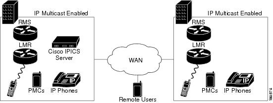
The Cisco IPICS single site model represents a deployment in a single multicast domain. Cisco IPICS components are located at one multicast-enabled site or campus, with no Cisco IPICS multicast services provided over an IP WAN. The single site model typically is deployed over a LAN or a metropolitan area network (MAN), either of which carries the multicast voice traffic within the site. Calls from beyond the LAN or MAN use the Cisco IPICS remote capability to connect to the Cisco IPICS domain via a SIP setup unicast call.
The single site model has the following design characteristics:
•
Cisco IPICS server
•
•
•
•
•
•
Figure 5-1 illustrates the Cisco IPICS single site model.
Figure 5-1 Single Site Model
Benefits of the Single Site Model
A single infrastructure for a converged network solution provides significant cost benefits and it enables Cisco IPICS to take advantage of the IP-based applications in an enterprise. In addition, a single site deployment allows a site to be completely self-contained. There is no dependency on an IP WAN, and a WAN failure or insufficient bandwidth will not cause loss of Cisco IPICS service or functionality.
Best Practices for the Single Site Model
When you implement a Cisco IPICS single site model, follow these guidelines:
•
•
•
Multiple Site Model
The Cisco IPICS multiple site model consists of a single Cisco IPICS server that provides services for two or more sites and that uses the IP WAN to transport multicast IP voice traffic between the sites. The IP WAN also carries call control signaling between the central site and the remote sites.
Multicast may be enabled between sites, but it does not have to be. Multiple sites connected by a multicast-enabled WAN are in effect a topologically different case of the single site model, because there is only one multicast domain. The main difference between multiple site model deployments is whether the connecting core network is a service provider network that employs Multiprotocol Label Switching (MPLS). If it is, MPLS with multicast VPNs is deployed to produce a single multicast domain between sites. Multiple sites with no native multicast support between sites can either employ Multicast over Generic Routing Encapsulation (GRE) or M1:U12:M2 connection trunks between sites. IPSec VPNs can also be configured between sites to secure inter-site traffic.
Figure 5-2 illustrates a typical Cisco IPICS multiple site deployment, with a Cisco IPICS server at the central site and an IP WAN to connect all the sites.
Figure 5-2 Multiple Site Model
In the multiple site model, connectivity options for the IP WAN include the following:
•
•
•
•
•
•
Routers that reside at the WAN edges require quality of service (QoS) mechanisms, such as priority queuing and traffic shaping, to protect the voice traffic from the data traffic across the WAN, where bandwidth typically is scarce.
MPLS with Multicast VPNs
MPLS does not support native multicast in an MPLS VPN. This section discusses a technique for enabling multicast across an MPLS core. This section assumes that the unicast MPLS core and the VPN have been configured and are operating properly, and it assumes that you are familiar with IP multicast and MPLS. For additional information about these topics, refer to the documentation at this URL:
http://www.cisco.com/en/US/products/ps6552/products_ios_technology_home.html
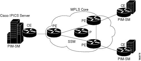
Figure 5-3 illustrates the topology that is discussed in this section.
Figure 5-3 MPLS with Multicast VPNs
MPLS Terminology
The following terms apply to MPLS:
•
•
•
•
•
•
•
•
•
MVPN Basic Concepts
The following basic concepts are key to understanding MVPN:
•
•
•
•
VPN Multicast Routing
A PE router in an MVPN network has several routing tables. There is one global unicast/multicast routing table and a unicast/multicast routing table for each directly connected MVRF.
Multicast domains are based on the principle of encapsulating multicast packets from a VPN in multicast packets to be routed in the core. Multicast is used in the core network, so PIM must be configured in the core. PIM-SM, PIM-SSM, and PIM-BIDIR are supported inside the provider core for MVPN. PIM-SM or PIM-SSM is the recommended PIM option in the provider core, because PIM-BIDIR is not supported on all platforms. PIM-SM, PIM-SSM, PIM-BIDIR and PIM-DENSE-MODE are supported inside the MVPN. MVPN leverages Multicast Distribution Trees (MDTs). An MDT is sourced by a PE router and has a multicast destination address. PE routers that have sites for the same MVPN source to a default MDT and join to receive traffic on it.
In addition, a Default-MDT is a tree that is always-on and that transports PIM control-traffic, dense-mode traffic, and rp-tree (*,G) traffic. All PE routers configured with the same default-MDT receive this traffic.
Data MDTs are trees that are created on demand and that will only be joined by the PE routers that have interested receivers for the traffic. Data MDTs can be created either by a traffic rate threshold or a source-group pair. Default-MDTs must have the same group address for all VPN Routing and Forwarding (VRFs) that make up a MVPN. Data MDTs may have the same group address if PIM-SSM is used. If PIM-SM is used, they must have a different group address, because providing the same one could result in the PE router receiving unwanted traffic.
Configuring the Provider Network for MVPN
This section provides an example of how to configure a provider network for MVPN.
The steps required to enable a MVPN in the provider network refer to the topology illustrated in Figure 5-3. In these steps, the customer VPN is called "ipics."
Procedure
Step 1
Cisco recommends PIM-SSM as the protocol in the core. No additional source-discovery BGP configuration is required with the source-discovery attribute. A route distinguisher (RD) type is used to advertise the source of the MDT with the MDT group address. PIM-SM is the most widely deployed multicast protocol and is used for both sparsely and densely populated application requirements. PIM SSM is based upon PIM SM. Without the initial Shared Tree and the subsequent cutover to the Shortest Path Tree, either PIM SSM or PIM SM is suitable for the default MDT.
When bidirectional PIM support becomes available on all relevant hardware, it will be the recommended for the default MDT. For the Data MDT, either PIM SM or PIM SSM is suitable. PIM SSM is simpler to deploy than PIM SM. It does not require a Rendezvous Point, and the provider network is a known and stable group of multicast devices. Cisco recommends the use of PIM SSM for provider core deployment. This configuration example uses PIM-SSM in the core.
Step 2
The default PIM-SSM range is 232/8. However, this address range is designed for global use in the Internet. For use within a private domain, use an address outside of this administratively scoped multicast range (as recommended in RFC 2365, Administratively Scoped Multicast). Using a private address range makes it simpler to filter on boundary routers. Cisco recommends using 239.232/16, because addresses in this range are easily recognizable as both private addresses and as SSM addresses by using 232 in the second octet. In the design that this document discusses, the range is divided for default-MDT and data MDT. (Data MDT is discussed in the "VPN Multicast Routing" section. Default-MDTs uses 239.232.0.0-239.232.0.255 and Data MDTs uses 239.232.1.0-239.232.1.255. This address range provides support for up to 255 MVRFs per PE router.
Step 3
The following commands enable a basic PIM-SSM service.
•
ip multicast-routingip pim ssm range multicast_ssm_rangeip access-list standard multicast_ssm_rangepermit 239.232.0.0 0.0.1.255•
ip pim sparse-mode•
ip pim sparse-modeStep 4
•
ip vrf ipicsmdt default 239.232.0.0•
ip multicast-routing vrf ipicsStep 5
The PIM mode inside the VPN depends on what type of PIM the VPN customer is using. Cisco provides automatic discovery of the group-mode that is used inside the VPN via auto-rp or bootstrap router (BSR), which requires no additional configuration. Optionally, a provider may choose to provide the RP for a customer by configuring the PE router as an RP inside the VPN. In the topology that this section discusses, the VPN customer provides the RP service and the PE routers automatically learn the group-to-rendezvous point (RP) via auto-rp.
Configure all PE-CE interfaces for sparse-dense-mode, which ensures that either auto-rp or BSR messages are received and forwarded, and which allows the PE to learn the group-to-RP inside the VPN. To do so, configure the following on all customer facing interfaces:
ip pim sparse-dense-mode
Verifying the Provider Network for MVPN
After you complete the configuration as described in the "Configuring the Provider Network for MVPN" section, use the following procedure to verify that the configuration is correct:
Procedure
Step 1
BGP provides for source discovery when SSM is used, which is known as a BGP-MDT update. To verify that all BGP-MDT updates have been received correctly on the PE routers, take either of these actions:
•
PE1#show ip pim mdt bgpPeer (Route Distinguisher + IPv4) Next HopMDT group 239.232.0.02:65019:1:10.32.73.248 10.32.73.248 (PE-2 Loopback)2:65019:1:10.32.73.250 10.32.73.250 (PE-3 Loopback)2:65019:1 indicates the RD-type (2) and RD (65019:1) that is associated with this update.
The remaining output is the address that is used to source the BGP session.
•
PE1#show ip bgp vpnv4 allBGP table version is 204, local router ID is 10.32.73.247Status codes: s suppressed, d damped, h history, * valid, > best, i - internal,r RIB-failure, S StaleOrigin codes: i - IGP, e - EGP, ? - incompleteNetwork Next Hop Metric LocPrf Weight PathRoute Distinguisher: 65019:1 (default for vrf ipics)*>i10.32.72.48/28 10.32.73.248 0 100 0 ?... (output omitted)Route Distinguisher: 2:65019:1*> 10.32.73.247/32 0.0.0.0 0 ?*>i10.32.73.248/32 10.32.73.248 0 100 0 ?*>i10.32.73.250/32 10.32.73.250 0 100 0 ?Step 2
Use the show ip mroute mdt-group-address command to verify that there is a (Source, Group) entry for each PE router. Because PIM-SSM is used, the source is the loopback address that is used to source the BGP session and the Group is the MDT address configured. Without traffic, only default-MDT entries are visible.
PE1#show ip mroute 239.232.0.0IP Multicast Routing TableFlags: D - Dense, S - Sparse, B - Bidir Group, s - SSM Group, C - Connected,L - Local, P - Pruned, R - RP-bit set, F - Register flag,T - SPT-bit set, J - Join SPT, M - MSDP created entry,X - Proxy Join Timer Running, A - Candidate for MSDP Advertisement,U - URD, I - Received Source Specific Host Report, Z - Multicast TunnelY - Joined MDT-data group, y - Sending to MDT-data groupOutgoing interface flags: H - Hardware switchedTimers: Uptime/ExpiresInterface state: Interface, Next-Hop or VCD, State/Mode(10.32.73.247, 239.232.0.0), 1w0d/00:03:26, flags: sTZIncoming interface: Loopback0, RPF nbr 0.0.0.0Outgoing interface list:FastEthernet0/0, Forward/Sparse, 1w0d/00:02:47(10.32.73.248, 239.232.0.0), 1w0d/00:02:56, flags: sTIZIncoming interface: FastEthernet0/0, RPF nbr 10.32.73.2Outgoing interface list:MVRF ipics, Forward/Sparse, 1w0d/00:01:30(10.32.73.250, 239.232.0.0), 1w0d/00:02:55, flags: sTIZIncoming interface: FastEthernet0/0, RPF nbr 10.32.73.2Outgoing interface list:MVRF ipics, Forward/Sparse, 1w0d/00:01:29Verify that the s flag is set on each (S,G) entry, which indicates that this group is used in ssm mode. Verify that the z flag is set, which indicates that this PE router is a leaf of the multicast tunnel. When the router is a leaf of a multicast tunnel, it has to perform additional lookups to determine which MVRF to forward this traffic to, as it is en effect a receiver for this traffic. Verify the I flag is set for the remote PE(S,G) entry. This flag indicates that the router understands it is joining an SSM group. It is as though an IGMPv3 host had requested to join that particular channel.
Step 3
Use the show ip pim neighbors command on all PE and P routers to verify that the pim neighbors are setup properly in the global table.
PE1#show ip pim neighborPIM Neighbor TableNeighbor Interface Uptime/Expires Ver DRAddress Prio/Mode10.32.73.2 FastEthernet0/0 1w4d/00:01:21 v2 1 / DR10.32.73.70 Serial0/2 1w4d/00:01:29 v2 1 / SStep 4
Use the show ip pim vrf ipics neighbors on all PE routers to verify that the CE router is seen as a PIM neighbor and that the remote-PE routers are seen as pim neighbors over the tunnel.
PE1#show ip pim vrf ipics neighborPIM Neighbor TableNeighbor Interface Uptime/Expires Ver DRAddress Prio/Mode10.32.73.66 Serial0/0 1w3d/00:01:18 v2 1 / S10.32.73.248 Tunnel0 3d17h/00:01:43 v2 1 / S10.32.73.250 Tunnel0 1w0d/00:01:42 v2 1 / DR SStep 5
The main customer site has been configured to use auto-rp within the VPN. VPN IPICS is using the multicast range 239.192.21.64 - 79 for channels and VTGs.
ip pim send-rp-announce Loopback0 scope 16 group-list multicast_rangeip pim send-rp-discovery scope 16ip access-list standard multicast_rangepermit 239.192.21.64 0.0.0.15Use the show ip pim vrf ipics rp mapping command to verify that the PE router correctly learned the group-to-RP mapping information from the VPN.
PE1#show ip pim vrf ipics rp mapPIM Group-to-RP MappingsGroup(s) 239.192.21.64/28RP 10.32.72.248 (?), v2v1Info source: 10.32.73.62 (?), elected via Auto-RPUptime: 1w3d, expires: 00:02:54This output shows that the PE router has correctly learned the group-to-RP, which is used inside the VPN. The default-MDT reaches all PE routers in the core of the provide network in which the multicast replication is performed. With only a default-MDT configured, traffic goes to all PE routers, regardless of whether they want to receive the traffic.
Optimizing Traffic Forwarding: Data MDT
Data MDT is designed to optimize traffic forwarding. Data MDT is a multicast tree that is constructed on demand. The conditions to create a data MDT are based upon traffic-load threshold measured in kbps or on an access-list that specifies certain sources inside the VPN. A data MDT is created only by the PE that has the source connected to its site. The data MDT conditions do not have to be configured. However, when there are no conditions set for each (S,G) inside the VPN, a data MDT is created. This data MDT requires resources from the router, so it is recommended that you not create one just because a source exists. A non-zero threshold is recommended, because this value requires an active source to trigger the creation of the Data MDT. The maximum number of multi-VPN Routing/Forwarding (MVRF) entries is 256.
To configure the data MDT under the VRF, use one of the ranges that is described in Step 2 in the "Configuring the Provider Network for MVPN" section. A maximum of 256 addresses is allowed per VRF. This limitation is an implementation choice, not a protocol limitation. Because SSM is used, the data MDT address-range may be the same on all PE routers for the same VPN. Use an inverse-mask to specify the number of addresses used for the data MDT, as shown in the following command:
ip vrf ipicsmdt data 239.232.1.0 0.0.0.255 threshold 1Verifying Correct Data MDT Operation
Data MDTs create mroute entries in the global table. There also are specific commands for verifying functionality of the sending and receiving PE router. To verify the data MDT operation, there must be multicast traffic between sites that exceeds the configured threshold. An easy way to test the data MDT is to statically join a multicast group in one site and then ping that group from another site, as shown in the following example:
CE1
interface Loopback0ip address 10.32.72.248 255.255.255.255ip pim sparse-dense-modeip igmp join-group 239.192.21.68CE2
ping 239.192.21.68 size 500 repeat 100To verify the data MDT operation, perform the following procedure:
Procedure
Step 1
Use the show ip pim vrf ipics mdt send command on the sending PE router (PE2) to verify the setup of a data mdt.
PE2#show ip pim vrf ipics mdt sendMDT-data send list for VRF: ipics(source, group) MDT-data group ref_count(10.32.72.244, 239.192.21.68) 239.232.1.0 1(10.32.73.74, 239.192.21.68) 239.232.1.1 1Step 2
Use the show ip pim vrf ipics mdt receive detail command on the receiving PE (PE1) router to verify that this router is receiving on a data mdt.
PE1#show ip pim vrf ipics mdt receiveJoined MDT-data [group : source] for VRF: ipics[239.232.1.0 : 10.32.73.248] ref_count: 1[239.232.1.1 : 10.32.73.248] ref_count: 1At this point, if everything is correctly configured, the sites in VPN IPICS can transfer multicast traffic using the MPVN and all sites are now in the same multicast domain. Therefore, all channels and users on the Cisco IPICS server can be configured with the same location.
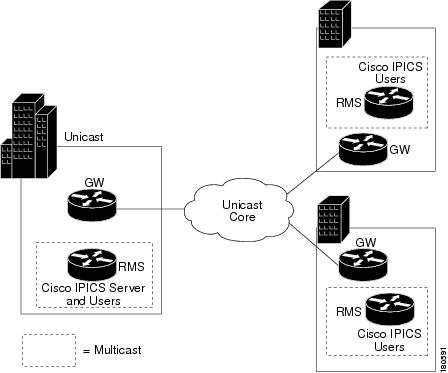
Multicast Islands
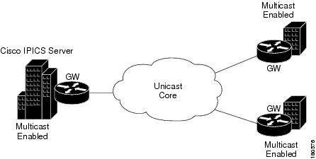
A multicast island is a site in which multicast is enabled. A multi-site deployment can consist of several multicast islands that connect to each other over unicast-only connections. See Figure 5-4.
Figure 5-4 Multicast Islands
You can use either of these techniques to provide multicast support between the islands:
Multicast over GRE
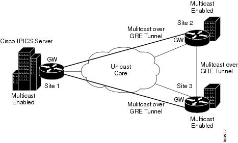
This section provides an overview of how to configure multicast over GRE. Figure 5-5 illustrates a Cisco IPICS deployment with multicast over GRE.
Figure 5-5 Multicast over a GRE Tunnel
A tunnel is configured between the gateway in Site 1 and the gateway in Site 2, which is sourced with their respective loopback0 interfaces. The ip pim sparse-dense mode command is configured on tunnel interfaces and multicast routing is enabled on the gateway routers. Sparse-dense mode configuration on the tunnel interfaces allows sparse-mode or dense-mode packets to be forwarded over the tunnel depending on the RP configuration for the group.
The following examples show the configuration that is required to implement multicast over GRE between Site 1 and Site 2. Use the same approach between Site 1and Site 3, and between Site 2 and Site 3
interface loopback 0ip address 1.1.1.1 255.255.255.255interface Tunnel0ip address 192.168.3.1 255.255.255.252ip pim sparse-dense-modetunnel source Loopback0tunnel destination 2.2.2.2Site 2
ip multicast-routinginterface loopback 0ip address 2.2.2.2 255.255.255.255interface Tunnel0ip address 192.168.3.2 255.255.255.252ip pim sparse-dense-modetunnel source Loopback0tunnel destination 1.1.1.1When you configure PIM sparse mode over a tunnel, make sure to follow these guidelines:
•
For example, assume that Site 1 has the RP (RP address 10.1.1.254). In this case, the mroute on the gateway in Site 2 would be the ip mroute 10.1.1.254 255.255.255.255 tunnel 0 command, which ensures a successful RPF check for traffic flowing over the shared tree.
•
In this case, when SPT traffic flows over the tunnel interface, an ip mroute 10.1.1.0 255.255.255.0 tunnel 0 command is configured on the Site 2 gateway and ip mroute 10.1.2.0 255.255.255.0 tunnel 0 command is configured on the Site 1 gateway. This configuration ensures successful RPF verification for incoming multicast packets over the Tu0 interface.
Bandwidth Considerations when using Multicast over GRE
Cisco IPICS can operate with either the G.711 or the G.729 codec. Table 5-1 lists the bandwidth requirements for a voice call over unicast connection trunks, based on the codec used, the payload size, and whether cRTP, VAD, or both are configured.
Bandwidth consumption across a tunnel depends on how many active channels/VTGs/PMC users are communicating between the sites.
The following cases are examples how to calculate bandwidth use across a tunnel.
Case 1: Active channel in Site 1 and Site 2.
All users in Site 1 are using one channel, and all users in Site 2 are using another channel. No multicast voice flows across the tunnel.
Case 2: Active channel has n users in site 1 and m users in site 2.
In the following example, Call bandwidth is the bandwidth value from Table 3-2.
Bandwidth 1 = Call bandwidth * n (Flow from site 1 to site 2)
Bandwidth 2 = Call bandwidth * m (Flow from site 2 to site 1)
Total bandwidth = Bandwidth 1 + Bandwidth 2
(Call bandwidth is the value from Table 3-1.)
Depending on the number of active channels, the number of active users per channel, and whether the channel spans multiple sites, the bandwidth usage could be significant.
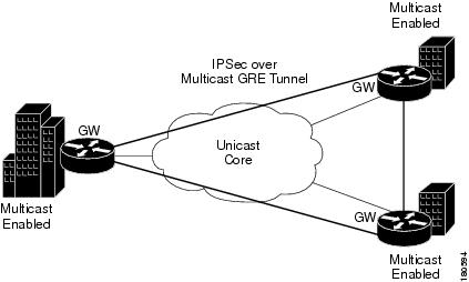
IPSec VPNs
IPSSec VPNs can be implemented over multicast GRE tunnels. See Figure 5-6.
Figure 5-6 IPSec over Multicast GRE Tunnels
There are a number of ways to configure IPSec over GRE tunnels. Refer to the appropriate Cisco documentation.
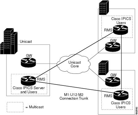
M1:U12:M2 Connection Trunks
M1:U12:M2 connection trunks provide an alternative to multicast over GRE tunnels for transporting real-time multicast voice traffic between Cisco IPICS islands. For example, consider the situation shown in Figure 5-7.
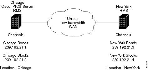
Figure 5-7 Unicast-Only Intersite Connection
In this example, the Stocks and Bonds Company has offices in Chicago and New York. Each location has two channels configured on the Cisco IPICS server. Because there is no multicast support between Chicago and New York, this scenario requires separate multicast domains, each with its own RP. The locations that are configured on the Cisco IPICS server represent the two multicast domains, Chicago and New York. The channels and the RMS in Chicago must be configured with location Chicago, and the channels and the RMS in New York must be configured with location New York.
Users in Chicago can communicate with each other using the Chicago Stocks or the Chicago Bonds channels. Users in New York can communicate with each other using the New York Stocks or the New York Bonds channels.
Chicago Stocks and Chicago Bonds can be placed in a VTG. Both of these channels have location Chicago, so the Cisco IPICS server mixes these channels using the RMS in Chicago. Similarly, New York Stocks and New York Bonds can be placed in a VTG. Both of these channels have location New York, so the Cisco IPICS server mixes these channels using the RMS in New York.
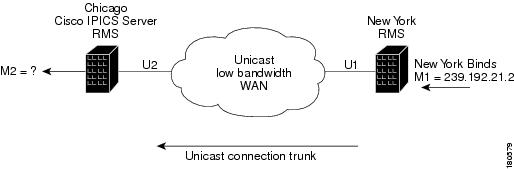
Interdomain VTGs are not possible. VTGs automatically have the location All, which assumes that all channels and users in the VTG are in the same multicast domain. You can work around this limitation using M1:U12:M2 connection trunks, as shown in Figure 5-8.
Figure 5-8 M1:U12:M2 Connection Trunk
In this example, assume that a VTG consisting of Chicago Bonds and New York Bonds is required. The M1:U12:M2 connection trunk maps the multicast traffic from the New York Bonds channel (M1) to a unicast address (U1) to transport this traffic across the unicast VoIP network. The unicast traffic that is received by the Chicago RMS is mapped to the multicast address M2. The M2 multicast address will be assigned to the New York Bonds proxy channel in Chicago and placed in a VTG with the Chicago Bonds channel. M2 should be assigned a valid multicast address in the Chicago multicast domain. To avoid conflicts, it should not be an address that is part of the multicast pool or an address that is used by any other channel.
Most deployments have a range of addresses that are allocated for channel use. The following list of ranges shows a typical approach:
239.192.21.1 - 16: Channel addresses
239.192.21.17 - 32: VTG addresses
Also assume that the following addresses have been assigned:
239.192.21.1: Chicago Bonds
239.192.21.2: Chicago Stocks
239.192.21.3: New York Bonds
239.192.21.4: New York Stocks
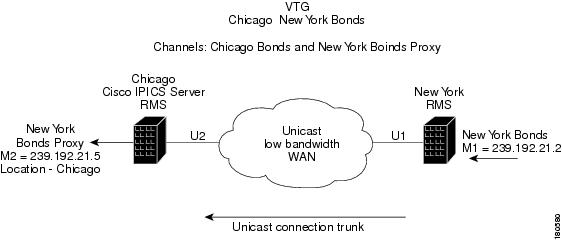
Now assume that the next free address, 239.192.21.5, is used for M2. A VTG can contain channels, users, or both. The VTG being created contains the channel Chicago Bonds, but it also needs to contain a channel that represents New York Bonds. The New York Bonds channel cannot be placed in the VTG because it is not multicast that can be reached by the RMS in Chicago. So a proxy channel is needed to represent the channel New York Bonds in location Chicago.
Figure 5-9 shows how to proxy the New York bonds channel in Chicago.
Figure 5-9 Proxy Channel
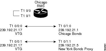
When the VTG called Chicago New York Bonds is created on the Cisco IPICS server, the VTG will contain two channels: Chicago Bonds and New York Bonds Proxy. The Cisco IPICS server configures the RMS in Chicago (both channels have location Chicago) to mix the two channels to the VTG. Assume that Cisco IPICS uses the multicast address 239.192.21.17 for the VTG. Two pairs of DS0s are required on the Chicago RMS to mix the channels to the VTG and the VTG to the channels. Figure 5-10 shows the configuration of the Chicago RMS, which is performed by the Cisco IPICS server for the VTG Chicago New York Bonds. This RMS configuration is the standard for a two-channel VTG.
Figure 5-10 VTG Configuration Performed by the Cisco IPICS Server
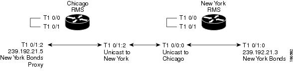
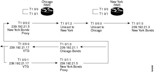
To implement the M1:U12:M2 connection trunk, you must manually configure the RMS. This configuration is needed to transport traffic from New York Bonds to the VTG and from the VTG to New York Bonds. See Figure 5-11.
Figure 5-11 M1:U12:M2 Trunk Configuration
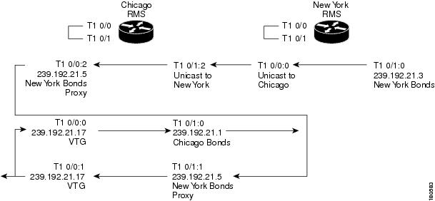
The traffic flow from New York to the VTG is shown in Figure 5-12. In this example, a user in New York is talking on channel New York Bonds on either a PMC, a Cisco Unified IP Phone, or a radio that is connected to an LMR gateway. The destination address is the multicast address that was assigned to the channel when the channel was configured on the Cisco IPICS server. When this traffic reaches the New York RMS, it is sent as unicast across the connection trunk to the Chicago RMS. The Chicago RMS maps the unicast traffic from New York to the New York Bonds Proxy channel, which is mapped to the VTG, which is mapped to the Chicago Bonds channel. Any user listening on either the VTG channel or the Chicago Bonds channel receives the traffic.
Figure 5-12 New York Bonds to the VTG and Chicago Bonds
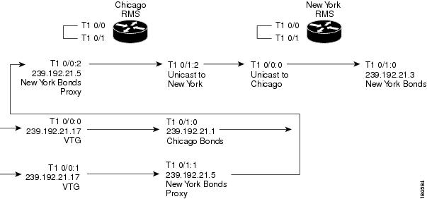
The traffic flow from the VTG to New York Bonds is shown in Figure 5-13. In this example, a user in Chicago talking on the VTG channel sends traffic to the multicast group 239.192.21.17. When this traffic reaches the Chicago RMS, it is mixed to both the New York Bonds Proxy channel and to the Chicago Bonds channel. The traffic that is mapped to the New York Bonds Proxy channel is sent as unicast across the connection trunk to New York, where it is mixed onto the New York Bonds channel.
Figure 5-13 VTG to Chicago and New York Bonds
The traffic flow from Chicago Bonds to New York Bonds is shown in Figure 5-14.
Figure 5-14 Chicago Bonds to VTG and New York Bonds
Whether traffic comes from the VTG (Figure 5-13) or from Chicago Bonds (Figure 5-14) depends on how the VTG is configured. A VTG can have channels, users, or both. If the VTG is created with channels only (Chicago Bonds and New York Bonds Proxy), users in Chicago will not see the VTG channel on their PMCs or Cisco Unified IP Phones. In addition, none of the Chicago users on channel Chicago Bonds or the New York users on channel New York Bonds will know that they are in a VTG. Users in Chicago will send and receive on channel Chicago Bonds and users in New York will send and receive on channel New York Bonds. The only traffic that is sent to or from the VTG channel is internal to the Chicago RMS.
If users associated with channel Chicago Bonds are also placed in the VTG, the VTG appears on their PMCs or Cisco Unified IP Phones. The users can then either activate channel Chicago Bonds or the VTG channel. If they activate the VTG channel, their traffic is sent to the VTG multicast address and mixed to the Chicago Bonds and New York Bonds Proxy channels on the Chicago RMS. Users associated with New York Bonds can never be placed in the VTG because they are in location New York and the VTG is being mixed on the RMS in Chicago.
This solution is symmetrical. The VTG could have been created with a Chicago Bonds Proxy with location New York and the New York Bonds channel. In that case, Cisco IPICS would use the New York RMS instead of the Chicago RMS and the operation would be identical to the example presented here.
Unicast Connection Trunk Configuration
This section describes the manual RMS configuration that is required for a unicast connection trunk to enable the M1:U12:M2 Chicago and New York Stocks and Bonds scenario.
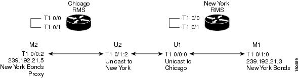
Figure 5-15 illustrates the components of the Unicast connection trunk that need to be configured between Chicago and New York.
Figure 5-15 Unicast Connection Trunk Components
Because there are no dialed numbers (from an LMR, PMC, or Cisco Unified IP Phone), the connection trunk digits command is used to generate the dialed number internally and to match a VoIP dial peer. The connection trunk command also establishes a permanent VoIP call between the RMS routers. The sample configuration that follows assumes the use of T1 resources on the RMS and that the T1 ports are configured as follows:
controller T1 0/0framing esfclock source internallinecode b8zscablelength short 133ds0-group 0 timeslots 24 type e&m-lmrds0-group 1 timeslots 1 type e&m-lmr...ds0-group 23 timeslots 23 type e&m-lmrIf you are using T1 resources on the RMS, Cisco IPICS must be configured to not use the DS0s that are used for the connection trunk.
The following example configuration uses DS0 resources from the RMS T1 loop back on 0/0 and 0/1, so the voice ports must be explicitly blocked to prevent the Cisco IPICS server from dynamically allocating them. To block the DS0s, use the Cisco IPICS Administration Console to disable port 0/0:2 in the Chicago RMS and to disable port 0/0:0 in the New York RMS. (For instructions, refer to the "Viewing and Configuring Loopbacks" section in Cisco IPICS Server Administration Guide.) When DS0s are in the Reserved state, the RMS does not attempt to dynamically allocate them.
The following table illustrates the manual configuration that is required to configure the U1 and U2 portions of the connection trunks in the Chicago RMS and New York RMS. In the Session Target fields, substitute the respective RMS Loopback0 IP address for the RMS name.
The following table illustrates the manual commands required to configure the voice port and dial peer entries in the New York RMS to enable the M1 portion of the M1:U12:M2 connection trunk.
The following table illustrates the manual commands required to configure the voice port and dial peer entries in the Chicago RMS to enable the M2 portion of the M1:U12:M2 connection trunk.
Connection Trunk Verification
The following output shows the IOS commands that can be used in an RMS to determine the status of the connection trunk. This sample output shows the dial peers used and shows that the trunked connections are in the connected state.
New York#show voice call statusCallID CID ccVdb Port DSP/Ch Called # Codec Dial-peers0xF 11F0 0x6772A350 0/0:0.24 0/13:1 2000 g729r8 2/10x11 11F3 0x67729198 0/1:0.24 0/13:3 2001 g711ulaw 0/32 active calls foundChicago#show voice call summary | i TRUNKED0/1:2.24 g729r8 y S_CONNECT S_TRUNKED0/0:2:0.24 g711ulaw y S_CONNECT S_TRUNKEDBandwidth Considerations for Unicast Connection Trunks
Hoot `n' holler mixing algorithms are described in "Cisco IPICS Component Considerations" and bandwidth considerations and are described in "Cisco IPICS Infrastructure Considerations." To determine the bandwidth required for one unicast connection trunk, find the bandwidth requirement for one voice stream in Table 3-2.
For example, using the G.729 codec, 20 byte payload size, and cRTP with VAD requires 7.3 kbps.
This calculation is the bandwidth for one connection trunk. If more than one connection trunk is used, multiply this number by the number of trunks.
Multicast Singularities
A multicast singularity is a restrictive case of the multicast island scenario. In this case, multicast routing is not enabled between sites. Within a site, multicast is enabled only on Cisco IPICS specific devices: RMS, LMR gateways, PMCs, and Cisco Unified IP Phones. These Cisco IPICS devices reside in a multicast singularity, as shown in Figure 5-16.
Figure 5-16 Multicast Singularities
The singularities can be connected by using multicast over GRE tunnels (as shown in Figure 5-17) or by using M1:U12:M2 connection trunks (as shown in Figure 5-18).
Figure 5-17 Multicast Singularities with GRE Tunnels
Figure 5-18 Multicast Singularities with M1:U12:M2 Connection Trunks
The configuration of a multicast over GRE tunnel is identical to the multicast island scenario except the tunnel must be configured between the RMS routers and not the gateway routers because the gateway routers are not enabled for multicast. The configuration of an M1:U12:M2 connection trunk is identical to the multicast islands scenario. In both cases, the trunk must be configured between the RMS routers.
The following rules apply to a multicast singularity:
•
•
•
•
It is possible to have multiple multicast singularities within the same site with the singularities connected with multicast over GRE tunnels. This solution depends on the policies of the organization.