Downloads |
 Feedback Feedback
|
Table Of Contents
Troubleshooting Security ImplementationsTroubleshooting CiscoSecure Scanner
Before Calling Cisco Systems' TAC Team
Troubleshooting CiscoSecure Intrusion Detection System (NetRanger)
Commands That Can Be Used to Troubleshoot the Application
Error Files Used for Debugging Application Errors
Before Calling Cisco Systems' TAC Team
Additional Debug Command Notes
External Users Cannot Access an Internal System (Web Server, Mail Server)
Before Calling Cisco Systems' TAC Team
PIX 520 Password Recovery Procedure
Downloading a PIX 515 Image over TFTP
Password-Recovery Procedure: Platforms Running Current Cisco IOS Releases
Password-Recovery Procedure: Platforms Running Recent Software Releases
Password-Recovery Procedure: Platforms Running Earlier Software Releases
Password-Recovery Procedure: IGS Running Software Prior to Software Release 9.1
Password-Recovery Procedure: Cisco 500-CS Communication Server
Troubleshooting Security Implementations
This chapter covers several of the security products used to protect the network. It includes scanning software (CiscoSecure Scanner, formerly known as NetSonar), intrusion-detection software (CiscoSecure Intrusion Detection System, formerly known as NetRanger), firewall software (Cisco PIX Firewall), and router and switch password recovery.
As the Internet grows, so does the possibility of illegal activities. These activities can range from denial-of-service attacks to the compromising of propriety data. Many products have been developed to protect networks.
Firewalls were the first security products introduced to prevent unauthorized entry into the protected network. They allow network access only to specifically configured protocols and network objects. Next came intrusion-detection software products. These products track authorized traffic permitted by the firewall, while searching for unauthorized activity such as hacking attempts or denial-of-service attacks. Finally there was scanning software, which allowed administrators to detect security vulnerabilities in their network design.
This chapter assists a network administrator in debugging the security products mentioned here that have been installed in the network. This chapter assumes that the reader is familiar with the installation and operation of the software products to be debugged.
Only debugging commands are discussed in this chapter. For more information about the command syntax or explanation for each software product, refer to the user manual. You can also find the commands under "Service and Support" in the "Technical Documentation" section of Cisco Connection Online (CCO).
In the creation of this chapter, care was taken to use only the latest versions of software. If you have earlier versions of software than those discussed here, refer to the user's manual for your product for proper commands and syntax.
Objectives
The objective of this chapter is to help those already familiar with installed security software products to do some basic troubleshooting or debugging.
Troubleshooting CiscoSecure Scanner
The majority (75 percent) of the CiscoSecure Scanner (NetSonar) problems deal with licensing. The license issues are being addressed and will change with the next release.
Table 25-1 describes the other 25 percent of common problems.
Before Calling Cisco Systems' TAC Team
Before calling Cisco Systems's Technical Assistance Center (TAC), make sure that you have read through this chapter and completed the actions suggested for your system's problem.
In addition, note and document the following information so that we may better assist you:
•
Operating system (Solaris or Windows NT) version
•
Troubleshooting CiscoSecure Intrusion Detection System (NetRanger)
The main objective of this section is to help diagnose problems that may occur when running CiscoSecure Intrusion Detection System (IDS). There are three parts to the IDS: the Director, and the Sensor, and the Post Office. The Sensor discussed in this section is the appliance, not the feature that is now available in the IOS. The Post Office is the communication backbone that allows NetRanger services and hosts to communicate with each other. All communication is supported by a proprietary, connection-based protocol that can switch between alternate routes to maintain point-to-point connections.
Commands That Can Be Used to Troubleshoot the Application
CiscoSecure IDS comes with several commands and logs that are highly valuable when troubleshooting a problem with the software. This section gives a brief description of each command and each log file, followed by an example. Later sections discuss when to use each command.
The following commands are used when troubleshooting:
•
netrangr@director>nrversApplication Versions for director.rtppostofficed v2.2.1 (release) 99/07/19-22:30loggerd v2.2.1 (release) 99/07/19-22:31packetd v2.2.1 (release) 99/07/19-22:44managed v2.2.1 (release) 99/07/19-22:29configd v2.2.1 (release) 99/07/19-22:29sapd v2.2.1 (release) 99/07/19-22:31fileXfer v2.2.1 (release) 99/07/19-22:36•
netrangr@director>nrstatusnetrangr 28906 1 99 Feb 05 ? 8295:01 /usr/nr/bin/nr.managednetrangr 28921 1 0 Feb 05 ? 0:04 /usr/nr/bin/nr.configdnetrangr 28948 1 0 Feb 05 ? 0:09 /usr/nr/bin/nr.fileXferdnetrangr 28936 1 0 Feb 05 ? 0:04 /usr/nr/bin/nr.sapdnetrangr 28877 1 0 Feb 05 ? 0:29 /usr/nr/bin/nr.loggerdnetrangr 28891 1 0 Feb 05 ? 6:17 /usr/nr/bin/nr.packetdnetrangr 28217 1 0 Feb 05 ? 6:47 /usr/nr/bin/nr.postofficed•
netrangr@director>nrconnsConnection Status for director.rtpsensor.rtp Connection 1: 171.68.120.214 45000 1 [Established] sto:0002 with Version 1sensor2.rtp Connection 1: 171.68.120.213 45000 1 [SynSent] sto:0002 with Version 1•
netrangr@director>nrestEstablished Connections for director.rtpsensor.rtp Connection 1: 171.68.120.214 45000 1 [Established] sto:0002 with Version 1•
netrangr@director>nrstopdone•
netrangr@director>nrstartstarting netranger services:netrangr 1671 1 0 09:28:49 pts/0 0:00 /usr/nr/bin/nr.postofficednetrangr 1781 1 0 09:28:51 ? 0:00 /usr/nr/bin/nr.configdnetrangr 1741 1 0 09:28:50 ? 0:00 /usr/nr/bin/nr.loggerdnetrangr 1823 1 0 09:28:51 pts/0 0:00 /usr/nr/bin/nr.fileXferdnetrangr 1751 1 0 09:28:50 ? 0:00 /usr/nr/bin/nr.packetdnetrangr 1766 1 0 09:28:50 ? 0:00 /usr/nr/bin/nr.managednetrangr 1796 1 0 09:28:51 ? 0:00 /usr/nr/bin/nr.sapdnetranger startup done.Error Files Used for Debugging Application Errors
The following files are located in the /usr/nr/etc directory. Each is created when you run the application the first time. If you delete these files and stop and start the application, these files will be re-created. However, if you do not delete these files, information will be appended on to it. Each file contains the error associated with that daemon. For example, communication errors would be found in the errors.postoffice file.
On the Sensor or appliance:
•
•
•
•
•
On the Director:
•
•
•
•
•
•
•
•
Table 25-2 shows symptoms, possible problems, and suggested actions to be taken when troubleshooting CiscoSecure IDS.
Before Calling Cisco Systems' TAC Team
Before calling Cisco Systems's Technical Assistance Center (TAC), make sure that you have read through this chapter and completed the actions suggested for your system's problem.
In addition, note and document the following information so that we can better assist you:
•
•
•
Troubleshooting PIX Firewall
To debug the PIX Firewall, you must first breakdown the task at hand. The following is a possible breakdown of a task, followed by solutions to possible problems, error codes, and debug commands. The symptoms and their likely solutions are included in Table 25-3. The error codes and their definitions should help in the interpretation of errors found in various logs. The debug commands are listed and accompanied by examples to assist in their use.
Finding the Real Problem
The PIX is the gateway to the Internet for the network and is normally blamed for problems that occur when a user cannot get out to the Internet. Although the PIX might be the problem, there are many other elements involved that might be causing the problem. Here you will find a list of other areas that could be causing the problem with a quick checklist.
•
–
–
–
•
–
–
–
•
–
–
–
–
•
–
–
As you can see, many other factors are involved when troubleshooting the PIX Firewall.
debug Commands
The following commands are helpful when debugging the PIX Firewall.
•
•
•
•
•
•
router#debug icmp traceInbound ICMP echo reply (len 32 id 1 seq 256) 192.150.50.1 > 192.150.50.42Outbound ICMP echo request (len 32 id 1 seq 512) 192.150.50.42 > 192.150.50.1Inbound ICMP echo reply (len 32 id 1 seq 512) 192.150.50.1 > 192.150.50.42Outbound ICMP echo request (len 32 id 1 seq 768) 192.150.50.42 > 192.150.50.1Inbound ICMP echo reply (len 32 id 1 seq 768) 192.150.50.1 > 192.150.50.42Outbound ICMP echo request (len 32 id 1 seq 1024) 192.150.50.42 > 192.150.50.1Inbound ICMP echo reply (len 32 id 1 seq 1024) 192.150.50.1 > 192.150.50.42•
router#debug packet inside--------PACKET ----------- IP --4.3.2.1 ==> 255.3.2.1ver = 0x4 hlen = 0x5 tos = 0x0 tlen = 0x60id = 0x3902 flags = 0x0 frag off=0x0ttl = 0x20 proto=0x11 chksum = 0x5885-—UDP --source port = 0x89 dest port = 0x89len = 0x4c checksum = 0xa6a0-—DATA --00000014: 00 01 00 00|....00000024: 00 00 00 01 20 45 49 45 50 45 47 45 47 45 46 46| .... EIEPEGEGEFF00000034: 43 43 4e 46 41 45 44 43 41 43 41 43 41 43 41 43| CCNFAEDCACACACAC00000044: 41 43 41 41 41 00 00 20 00 01 c0 0c 00 20 00 01| ACAAA.. ..... ..00000054: 00 04 93 e0 00 06 60 00 01 02 03 04 00| ......\Q......--------END OF PACKET ---------•
Syntax description:
–
–
–
–
–
–
–
–
–
–
–
–
In the following example, the contents of the tcp packets on port 25 with the source address of 200.200.200.20 and the destination address of 100.100.100.10 are displayed.
debug packet outside src 200.200.200.20 dst 100.100.100.10 proto tcp dport 25 both
Note
Additional Debug Command Notes
The debug icmp trace command now sends output to the Trace Channel. The location of the Trace Channel depends on whether you have a simultaneous Telnet console session running at the same time as the console session, or if you are using only the PIX Firewall serial console.
If you are using only the PIX Firewall serial console, all debug commands display on the serial console.
If you have both a serial console session and a Telnet console session accessing the console, then no matter where you enter the debug icmp trace or the debug sqlnet commands, the output displays on the Telnet console session.
If you have two or more Telnet console sessions, the first session is the Trace Channel. If that session closes, the serial console session becomes the Trace Channel. The next Telnet console session that accesses the console will then become the Trace Channel.
The debug packet command displays only on the serial console. However, you can enable or disable this command from either the serial console or a Telnet console sessions.
The debug commands are shared between all Telnet and serial console sessions.
Note
Note
Troubleshooting Steps
The first example deals with an internal user who cannot access the Internet. These are recommended troubleshooting steps to follow, but note that these steps may not solve every instance of this problem.
Step 1
•
•
a.
b.
•
a.
Route inside 0.0.0.0 0.0.0.0 100.100.100.2 1Route inside 0.0.0.0 0.0.0.0 100.100.100.2 1b.
Step 2
•
conduit permit icmp any any
Note
•
show xlate local ip_address•
clear xlate local ip_addressStep 3
Step 4
Step 5
Step 6
Step 7
External Users Cannot Access an Internal System (Web Server, Mail Server)
The following six steps provide a practical approach to troubleshooting common problems associated with external users having difficulty accessing a company's internet/mail servers.
Step 1
conduit permit icmp any anyStep 2
Note
Step 3
Step 4
Step 5
–
–
Step 6
Troubleshooting Techniques
Table 25-3 suggests what actions to take when presented with the two most common Pix firewall connectivity problems.
Before Calling Cisco Systems' TAC Team
Before calling Cisco Systems' Technical Assistance Center (TAC), make sure that you have read through this chapter and completed the actions suggested for your system's problem.
Additionally, do the following and document the results so that we can better assist you:
•
•
Additional Sources
Books:
•
•
URLs:
•
•
•
PIX Maintenance
The PIX has two important maintenance features:
•
•
These are discussed in the next sections.
Password Recovery
The password recovery for the PIX 515 requires a TFTP server to download the password data to it because that model does not have a floppy drive. For the other PIX models, use the following procedure.
A password recovery image will be available. This image will need to be copied using TFTP to the PIX just like any new upgrade image.
The TFTP capabilities directly take the place of the floppy loader, so, all previous functions that were handled with a floppy will be handled with TFTP.
Please note the following:
•
•
•
•
•
PIX 520 Password Recovery Procedure
The following is the recommended process for recovering lost passwords in PIX 520 firewalls.
Step 1
Step 2
RaWrite 1.2—Write the disk file to a raw floppy disk.
Step 3
Step 4
Step 5
The Rawrite program then writes the password recovery image to disk.
Step 6
Downloading a PIX 515 Image over TFTP
Because the PIX 515 does not have a floppy drive, the only method of password recovery available is by downloading a recovery program from a TFTP server. The TFTP capabilities directly take the place of the floppy loader, so all previous functions that were handled with a floppy will be handled with TFTP.
Please note the following:
•
•
•
•
•
The PIX 515 receives its boot image either from Flash memory or by downloading the image from a TFTP server.
This section describes the monitor command, which you will invoke while the PIX 515 is booting by sending a Break character or pressing the Escape key.
Because the PIX 515 does not have a disk drive, you need to send a binary image to the PIX 515 using TFTP.
The PIX 515 has a special mode called monitor mode that lets you retrieve the binary image over the network. When you power on or reboot the PIX 515, it waits 10 seconds, during which you can send a break character or press the Escape key to activate monitor mode.
If you do not want to enter the boot mode, press the Spacebar to start the normal boot immediately, or wait until the 10 seconds have finished, and the PIX 515 will boot normally.
While in monitor mode, you can enter commands that let you specify the location of the binary image, download it, and reboot the PIX 515 from the new image. If you do not activate monitor mode, the PIX 515 boots normally from Flash memory.
Monitor mode also lets you ping the TFTP server to see if it is online and to specify the IP address of the nearest router if the image is not on a subnet shared with a PIX 515 interface.
The monitor feature works only on the PIX 515 and not with earlier models of the PIX Firewall. TFTP does not perform authentication when transferring files, so a username and password on the TFTP server are not required.
If you are using Windows Hyperterminal, you can press the Esc (Escape) key or send a Break character by pressing the Ctrl and break keys.
From a Telnet session to a terminal server that has serial access to the PIX 515, use Ctrl-] to get the Telnet command prompt, and then enter the send break command.
If the TFTP service stops receiving data requests during a file transfer, it waits 4 seconds and then closes the connection.
To download an image over TFTP, use the following procedure:
Step 1
The monitor prompt appears.
Step 2
Step 3
Step 4
Step 5
Step 6
Step 7
Step 8
Step 9
Step 10
Software Upgrade Paths
The software upgrade procedure that you follow depends on whether you want to keep your configuration files intact. If you do, use the procedure outlined in Table 25-4.
If you don't care about retaining the configuration information, you can upgrade directly from the current version to the latest version.
Recovering a Lost Password
This section describes the procedures required to recover a lost login or enable password. The procedures differ, depending on the platform and the software used, but in all cases, password recovery requires that the router be taken out of operation and powered down.
If you need to perform one of the following procedures, make certain that secondary systems can temporarily serve the functions of the router undergoing the procedure. If this is not possible, advise all potential users and, if possible, perform the procedure during low-use hours.
Note
All the procedures for recovering lost passwords depend on changing the configuration register of the router. Depending on the platform and software you are using, this will be done by reconfiguring the router software or by physically moving a jumper or DIP switch on the router.
Table 25-5 shows which platforms have configuration registers in software and which require that you change the jumper or DIP switch position to change the configuration register.
Password-Recovery Procedure: Platforms Running Current Cisco IOS Releases
Recent Cisco platforms run from Flash memory or are booted from the network and can ignore the contents of nonvolatile RAM (NVRAM) upon booting. (Cisco 7000 series routers that boot from Flash memory or netboot have this capability as well; a Cisco 7000 that boots from ROM has this capability if it is running Cisco IOS Release 10.0 or later.) Ignoring the contents of NVRAM permits you to bypass the configuration file (which contains the passwords) and to gain complete access to the router. You can then recover the lost password or configure a new one.
Note
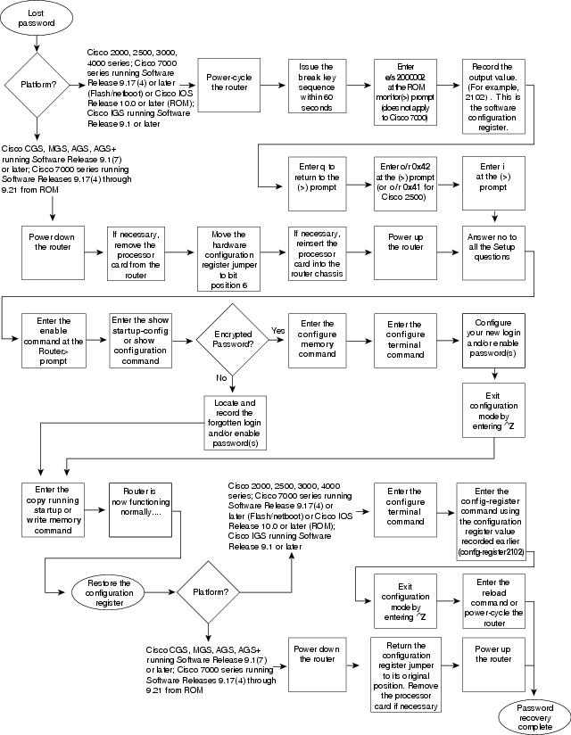
Figure 25-1 shows a flowchart describing the password-recovery procedure for the following platforms:
•
•
•
•
•
Some of these platforms are configurable in software. Others require that you physically change the position of the configuration register jumper on the processor card. Figure 25-1 shows diverging paths, when necessary, to take you through the steps required for the platform and software with which you are working.
Refer to Table 25-5 to determine whether the platform with which you are working is configurable in software, or if it requires you to physically move the jumper.
Figure 25-1 Password Recovery: Platforms Running Current Cisco IOS Releases and Recent Software Releases
The next procedure describes the password-recovery process for the following platforms only:
•
•
•
For the platforms listed, be certain to follow the path labeled "Cisco 2000, 2500, 3000, 4000 series; Cisco 7000 series running Software Release 9.17(4) or later (Flash) or Cisco IOS Release 10.0 or later (ROM); IGS running Software Release 9.1 or later" in the flowchart (see Figure 25-1).
For the step-by-step password recovery sequence for other platforms, see one of the following sections:
•
•
•
•
Note
The following is the password-recovery procedure for Cisco platforms running current Cisco IOS software:
Step 1
Step 2
The ROM monitor (>) prompt will appear.
Step 3
Record the output resulting from this command. This is the software configuration register value.
Step 4
Step 5
Step 6
Step 7
Step 8
Step 9
Step 10
If your password is encrypted, continue with Step 11.
Step 11
Step 12
Step 13
enable password [level level] {password | encryption-type encrypted-password}
Syntax description:
•
•
•
•
Example:
In the following example, the password pswd2 is enabled for privilege level 2:
enable password level 2 pswd2
If you lost the login password, configure the console line using the login and password line configuration commands. Enter CTRL Z to exit configuration mode, and proceed to Step 15.
Syntax:
To enable password checking at login, use the login line configuration command:
login [local | tacacs]
Syntax description:
•
•
Examples:
The following example sets the password letmein on virtual terminal line 4:
line vty 4password letmeinloginSyntax:
To specify a password on a line, use the password line configuration command:
password password
Syntax description:
•
When an exec process is started on a line with password protection, the exec prompts for the password. If the user enters the correct password, the exec prints its normal privileged prompt. The user can try three times to enter a password before the exec exits and returns the terminal to the idle state.
Example:
The following example removes the password from virtual terminal lines 1 to 4:
line vty 1 4no passwordStep 14
If you lost the login password, find the configuration entries for the console line, and record the password indicated by the password line configuration command.
Step 15
Note
The router is now fully functional, and you can use your recovered or reconfigured passwords as usual.
Note
Step 16
Step 17
Syntax:
The following is the syntax for config-register command:
config-register value
Syntax description:
•
Step 18
The next time the router is power-cycled or restarted with the reload privileged exec command, the bootup process will proceed as normal. Use your new or recovered password to gain access to the router after it reboots.
Password-Recovery Procedure: Platforms Running Recent Software Releases
The Cisco CGS, MGS, AGS, and AGS+ platforms, and the Cisco 7000 series routers running software prior to Cisco IOS Release 10.0 from ROM all have their configuration registers in hardware, so you must physically change the position of the configuration register jumper during the password-recovery process.
It might be necessary to remove the processor card from the router chassis to access the hardware configuration register jumper. Consult your hardware documentation for detailed instructions on removing and inserting the processor card from the router chassis, if necessary.
Moving the hardware configuration register jumper to bit position 6 allows the router to ignore the contents of NVRAM while booting. This permits you to bypass the configuration file (and, therefore, the passwords) and gain complete access to the router. You can then recover the lost password or configure a new one.
Note
Figure 25-1 shows a flowchart describing the password-recovery procedure for the following platforms:
•
•
•
•
•
Some of these platforms are configurable in software and do not require a hardware change. Others require that you physically change the position of the configuration register jumper on the processor card.
Refer to Table 25-5 to determine whether the platform on which you are working is configurable in the software, or whether it requires you to physically move the jumper.
The following procedure describes the password-recovery process for the following platforms only:
•
•
For these platforms, follow the path labeled "Cisco CGS, MGS, AGS, AGS+ running Software Release 9.1(7) or later; Cisco 7000 series running Software Release 9.17(4) through 9.21 from ROM" in the flowchart (see Figure 25-1).
For the step-by-step password recovery sequence for other platforms, see one of the following sections:
•
•
•
•
Note
The following is the password-recovery procedure for Cisco platforms running recent software releases:
Step 1
Step 2
Note
Step 3
The router will boot but will ignore the contents of NVRAM and enter the Setup routine.
Step 4
The Router prompt appears.
Step 5
Step 6
If the password is in clear text, go to Step 10. If the password is encrypted, continue with Step 7.
Step 7
Step 8
Step 9
If you have lost the login password, configure the console line with a new login password using the login and password line configuration commands. Press CTRL-Z to exit configuration mode. Proceed to Step 11.
Syntax:
To enable password checking at login, use the login line configuration command:
login [local | tacacs]
Syntax description:
•
•
Examples:
The following example sets the password letmein on virtual terminal line 4:
line vty 4password letmeinloginSyntax:
To specify a password on a line, use the password line configuration command:
password password
Syntax description:
•
When an exec process is started on a line with password protection, the exec prompts for the password. If the user enters the correct password, the exec prints its normal privileged prompt. The user can try three times to enter a password before the exec exits and returns the terminal to the idle state.
Example:
The following example removes the password from virtual terminal lines 1 to 4:
line vty 1 4no passwordStep 10
If you have lost the login password, find the configuration entries for the console line, and record the password indicated by the password line configuration command.
Step 11
Step 12
Note
Step 13
Step 14
It might be necessary to remove the processor card to gain access to the jumper. Consult your hardware documentation for complete instructions on removing and inserting the processor card, if necessary. If you had to remove the processor card, reinsert it before continuing.
Step 15
Password-Recovery Procedure: Platforms Running Earlier Software Releases
Cisco CGS, MGS, AGS, and AGS+ platforms, and Cisco 7000 series routers running software prior to Cisco IOS Release 10.0 from ROM all have their configuration registers in the hardware, so you must physically change the position of the configuration register jumper during the password-recovery process.
It might be necessary to remove the processor card from the router chassis to access the hardware configuration register jumper. Consult your hardware documentation for detailed instructions on removing and inserting the processor card from the router chassis, if necessary.
Note
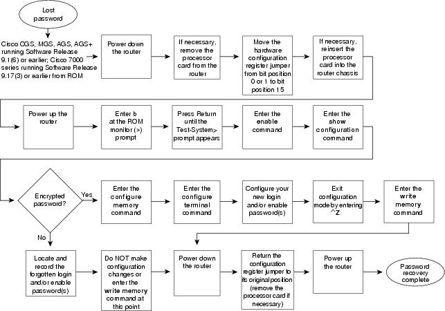
Figure 25-2 shows a flowchart that describes the password-recovery procedure for the following platforms:
•
•
The step-by-step procedure that follows and the password recovery flowchart shown in Figure 25-2 apply only to the indicated platforms running the indicated software. There is another procedure for recovering a password on these platforms if they are running more recent software. See the previous section, "Password-Recovery Procedure: Platforms Running Recent Software Releases."
Figure 25-2 Password Recovery: Platforms Running Earlier Software Releases
Note
The following is the password-recovery procedure for Cisco platforms running earlier software releases:
Step 1
Step 2
Note the original position of the jumper.
Note
Step 3
Step 4
Step 5
Step 6
Step 7
If the password is clear-text, go to Step 12.
If the password is encrypted, continue with Step 8.
Step 8
This writes the stored configuration into running memory.
Step 9
Step 10
If you have lost the login password, configure the console line with a new password using the login and password line configuration commands. Press CTRL-Z to exit configuration mode.
Syntax:
To enable password checking at login, use the login line configuration command:
login [local | tacacs]
Syntax description:
•
•
Examples:
The following example sets the password letmein on virtual terminal line 4:
Syntax:
To specify a password on a line, use the password line configuration command:
password password
Syntax description:
•
When an exec process is started on a line with password protection, the exec prompts for the password. If the user enters the correct password, the exec prints its normal privileged prompt. The user can try three times to enter a password before the exec exits and returns the terminal to the idle state.
Example:
The following example removes the password from virtual terminal lines 1 to 4:
line vty 1 4no passwordStep 11
Step 12
If you have lost the login password, find the configuration entries for the console line, and record the password indicated by the password line configuration command. Do not make configuration changes or use the write memory command at this time.
Step 13
Step 14
Step 15
Password-Recovery Procedure: IGS Running Software Prior to Software Release 9.1
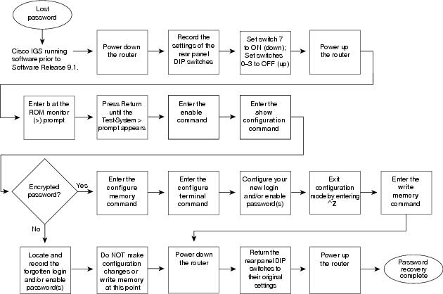
Cisco IGS routers have a bank of DIP switches located on the rear panel. These DIP switches are used to set the hardware configuration register and must be used in the password-recovery process if the router is running system software prior to Software Release 9.1.
Note
Figure 25-3 shows the password-recovery procedure for the Cisco IGS running software prior to Software Release 9.1. There is another procedure for the IGS platform if it is running Software Release 9.1 or later. See the section "Password-Recovery Procedure: Platforms Running Current Cisco IOS Releases."
Note
The following is the password-recovery procedure for IGS routers running software prior to Software Release 9.1:
Step 1
Step 2
Figure 25-3 Password Recovery: IGS Running Software Release Prior to 9.1
Step 3
Step 4
Step 5
The router will boot up, and the terminal will display the ROM monitor (>) prompt.
Step 6
Step 7
Step 8
Step 9
If the password is encrypted, continue with Step 10.
Step 10
Step 11
Step 12
If you have lost the login password, configure a new password on the console line using the login and password line configuration commands. Press ^Z to exit configuration mode.
Syntax:
To enable password checking at login, use the login line configuration command:
login [local | tacacs]
Syntax description:
•
•
Examples:
The following example sets the password letmein on virtual terminal line 4:
line vty 4password letmeinloginSyntax:
To specify a password on a line, use the password line configuration command:
password password
Syntax description:
•
When an exec process is started on a line with password protection, the exec prompts for the password. If the user enters the correct password, the exec prints its normal privileged prompt. The user can try three times to enter a password before the exec exits and returns the terminal to the idle state.
Example:
The following example removes the password from virtual terminal lines 1 to 4:
line vty 1 4no passwordStep 13
Step 14
Step 15
If you have lost the login password, find the configuration entries for the console line and record the password indicated by the password line configuration command. Do not make configuration changes or use the write memory command at this time.
Step 16
Step 17
Step 18
Password-Recovery Procedure: Cisco 500-CS Communication Server
Lost passwords cannot be recovered from Cisco 500-CS communication servers. The only way to recover from a lost password is to return the communication server to its factory default configuration using the Reset button located on the top of the case.
The following procedure describes how to restore the Cisco 500-CS to its default configuration.
Caution
Step 1
Step 2
Step 3
You must reconfigure the communication server.