Feedback Feedback
|
Table Of Contents
Troubleshooting LAN Switching Environments
Transparent Bridging Algorithm
How to Learn About These Features
General Switch Troubleshooting Suggestions
Troubleshooting Port Connectivity Problems
Troubleshooting Ethernet 10/100-Mb
Half-/Full-Duplex AutonegotiationTroubleshooting Ethernet Autonegotiation Between Network Infrastructure Devices
Example of Configuring and Troubleshooting Ethernet 10/100-Mb Autonegotiation
Before Calling Cisco Systems' TAC Team
ISL Trunking on Catalyst 5000 and 6000 Family Switches
Troubleshooting ISL Trunking on Catalyst 5000 and 6000 Family Switches
Example of Configuring and Troubleshooting ISL Trunking on Catalyst 5000 and 6000 Family Switches
Possible Combinations of DTP Configurations
Before Calling Cisco Systems' TAC Team
Configuring EtherChannel Switch-to-Switch Connections on Catalyst 4000/5000/6000 Switches
Tasks for Manually Configuring EtherChannel
Verifying the EtherChannel Configuration
Using PAgP to Automatically Configure EtherChannel (Preferred Method)
Waiting Too Long Before Configuring the Other Side
Showing What Happens When a Link Breaks and Is Restored
Using PortFast and Other Commands to Fix End-Station Startup Connectivity Problems
How to Reduce Startup Delay on the Catalyst 4000/5000/6000 Switch
Timing Tests with and Without DTP, PAgP, and PortFast on a Catalyst 5000
How to Reduce Startup Delay on the Catalyst 2900XL/3500XL Switch
Timing Tests on the Catalyst 2900XL
How to Reduce Startup Delay on the Catalyst 1900/2800 Switch
Timing Tests on the Catalyst 1900
An Additional Benefit to PortFast
Commands to Use for Verifying That the Configuration Is Working
Commands to Use for Troubleshooting the Configuration
Configuring and Troubleshooting IP Multilayer Switching
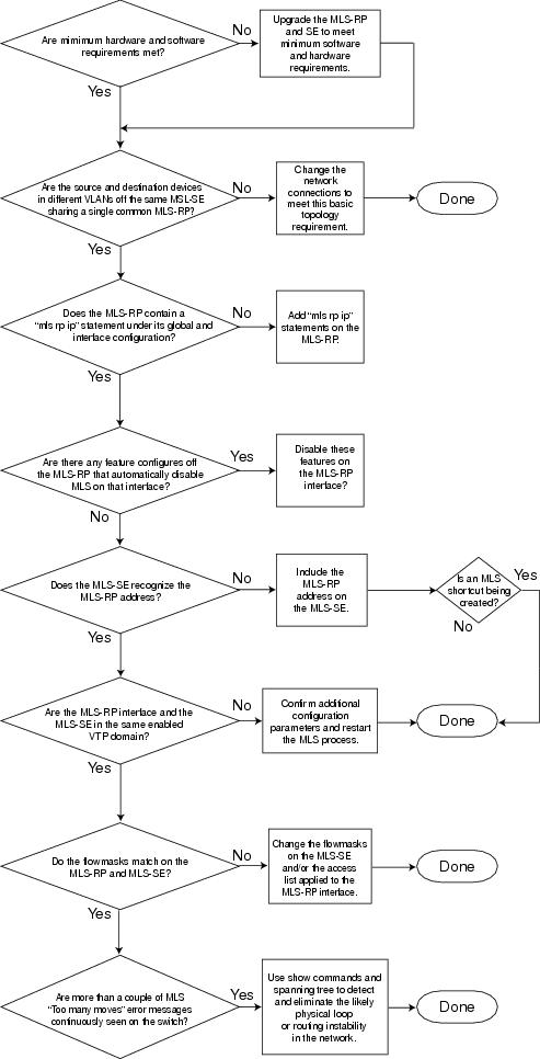
Troubleshooting IP MLS Technology
Before Calling Cisco Systems' TAC Team
Troubleshooting Spanning-Tree Protocol and Related Design Considerations
Spanning-Tree Protocol Failure
Awkward STP Parameter Tuning and Diameter Issues
Use the Diagram of the Network
Restore Connectivity Quickly and Be Ready for Another Time
Designing STP to Avoid Trouble
Minimize the Number of Blocked Ports
Keep STP Even If It Is Not Needed
Keep Traffic Off the Administrative VLAN, and Avoid Having a Single VLAN Spanning the Entire Network
Troubleshooting LAN Switching Environments
The sections in this chapter describe common LAN switch features and offer solutions to some of the most common LAN switching problems. The following items will be covered:
•
LAN Switching Introduction
•
•
•
•
•
•
•
•
•
LAN Switching Introduction
If you are new to LAN switching, then the following sections will take you through some of the main concepts related to switches. One of the prerequisites to troubleshooting any device is to know the rules under which it operates. Switches have become much more complex over the last few years as they have gained popularity and sophistication. The next few paragraphs describe some of the key concepts to know about switches.
Hubs and Switches
Because of the great demand placed on local-area networks, we have seen a shift from a shared-bandwidth network, using hubs and coaxial cable, to a dedicated bandwidth network, using switches. A hub allows multiple devices to be connected to the same network segment. The devices on that segment share the bandwidth with each other. If it is a 10-Mb hub and six devices are connected to six different ports on the hub, all six devices would share the 10 Mb of bandwidth with each other. A 100-Mb hub would share 100 Mb of bandwidth among the connected devices. In terms of the OSI model, a hub would be considered a Layer 1 (physical layer) device. It hears an electrical signal on the wire and passes it along to the other ports.
A switch can physically replace a hub in your network. A switch allows multiple devices to be connected to the same network, just like a hub does, but this is where the similarity ends. A switch allows each connected device to have dedicated bandwidth instead of shared bandwidth. The bandwidth between the switch and the device is reserved for communication to and from that device alone. Six devices connected to six different ports on a 10-Mb switch would each have 10 Mb of bandwidth to work with, instead of sharing that bandwidth with the other devices. A switch can greatly increase the available bandwidth in your network, which can lead to improved network performance.
Bridges and Switches
A basic switch would be considered a Layer 2 device. When we use the word layer, we are referring to the seven-layer OSI model. A switch does not just pass electrical signals along, like a hub does; instead, it assembles the signals into a frame (Layer 2) and then decides what to do with the frame. A switch determines what to do with a frame by borrowing an algorithm from another common networking device, a transparent bridge. Logically, a switch acts just like a transparent bridge would, but it can handle frames much faster than a transparent bridge (because of special hardware and architecture). When a switch decides where the frame should be sent, it passes the frame out the appropriate port (or ports). You can think of a switch as a device creating instantaneous connections between various ports, on a frame-by-frame basis.
VLANs
Because the switch decides on a frame-by-frame basis which ports should exchange data, it is a natural extension to put logic inside the switch to allow it to select ports for special groupings. This grouping of ports is called a virtual local-area network (VLAN). The switch makes sure that traffic from one group of ports never gets sent to other groups of ports (which would be routing). These port groups (VLANs) can each be considered an individual LAN segment.
VLANs are also described as being broadcast domains. This is because of the transparent bridging algorithm, which says that broadcast packets (packets destined for the "all devices" address) should be sent out all ports that are in the same group (that is, in the same VLAN). Therefore, all ports that are in the same VLAN are also in the same broadcast domain.
Transparent Bridging Algorithm
The transparent bridging algorithm and the Spanning-Tree Protocol are covered in more detail elsewhere (see Chapter 20, "Troubleshooting Transparent Bridging Environments"). When a switch receives a frame, it must decide what to do with that frame. It could ignore the frame, it could pass the frame out one other port, or it could pass the frame out many other ports.
To know what to do with the frame, the switch learns the location of all devices on the segment. This location information is placed in a CAM table (Content Addressable Memory, named for the type of memory used to store these tables). The CAM table shows, for each device, the device's MAC address, out which port that MAC address can be found, and which VLAN this port is associated with. The switch continually does this learning process as frames are received into the switch. The switch's CAM table is continually being updated.
This information in the CAM table is used to decide how a received frame should be handled. To decide where to send a frame, the switch looks at the destination MAC address in a received frame and then looks up that destination MAC address in the CAM table. The CAM table shows which port the frame should be sent out for that frame to reach the specified destination MAC address.
These are the basic rules that a switch will use in carrying out the frame forwarding responsibility:
If the destination MAC address is found in the CAM table, then the switch will send the frame out the port that is associated with that destination MAC address in the CAM table. This is called forwarding.
If the associated port to send the frame out is the same port on which the frame originally came in, then there is no need to send the frame back out that same port, and the frame is ignored. This is called filtering.
If the destination MAC address is not in the CAM table (the address is unknown), then the switch will send the frame out all other ports that are in the same VLAN as the received frame. This is called flooding. It will not flood the frame out the same port on which the frame was received.
If the destination MAC address of the received frame is the broadcast address (FFFF.FFFF.FFFF), then the frame is sent out all ports that are in the same VLAN as the received frame. This is also called flooding. The frame will not be sent out the same port on which the frame it was received.
Spanning-Tree Protocol
As we have seen, the transparent bridging algorithm floods unknown and broadcast frames out all the ports that are in the same VLAN as the received frame. This causes a potential problem. If the network devices running this algorithm are connected in a physical loop, then flooded frames (such as broadcasts) will be passed from switch to switch, around and around the loop forever. Depending on the physical connections involved, the frames may actually multiply exponentially as a result of the flooding algorithm, which can cause serious network problems.
There is a benefit to having a physical loop in your network: It can provide redundancy. If one link fails, there is still another way for the traffic to reach its destination. To allow the benefits derived from redundancy, without breaking the network because of flooding, a protocol called the Spanning-Tree Protocol was created. It was standardized in the IEEE 802.1d specification.
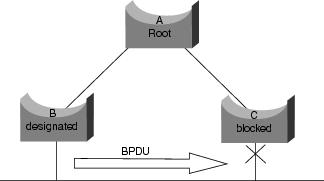
The purpose of the Spanning-Tree Protocol is to identify and temporarily block the loops in a network segment or VLAN. The switches run the Spanning-Tree Protocol, which involves electing a root bridge or switch. The other switches measure their distance from the root switch. If there is more than one way to get to the root switch, then there is a loop. The switches follow the algorithm to determine which ports should be blocked to break the loop. STP is dynamic; if a link in the segment fails, then ports that were originally blocking may possibly be changed to forwarding mode.
Trunking
Trunking is a mechanism that is most often used to allow multiple VLANs to function independently across multiple switches. Routers and servers may use trunking as well, which allows them to live simultaneously on multiple VLANs. If your network has only one VLAN in it, then you may never need trunking; if your network has more than one VLAN, however, you will probably want to take advantage of the benefits of trunking.
A port on a switch normally belongs to only one VLAN; any traffic received or sent on this port is assumed to belong to the configured VLAN. A trunk port, on the other hand, is a port that can be configured to send and receive traffic for many VLANs. It accomplishes this by attaching VLAN information to each frame, a process called "tagging" the frame. Also, trunking must be active on both sides of the link; the other side must be expecting frames that include VLAN information for proper communication to occur.
Different methods of trunking exist, depending on the media being used. Trunking methods for Fast Ethernet or Gigabit Ethernet are Inter-Switch Link (ISL) or 802.1q. Trunking over ATM uses LANE. Trunking over FDDI uses 802.10.
EtherChannel
EtherChannel is a technique that can be used when you have multiple connections to the same device. Instead of having each link function independently, EtherChannel groups the ports together to work as one unit. It distributes traffic across all the links and provides redundancy in case one or more links fail. EtherChannel settings must be the same on both sides of the links involved in the channel. Normally, the Spanning-Tree Protocol would block all these parallel connections between devices because they are loops; however, EtherChannel runs "underneath" Spanning-Tree Protocol so that the protocol thinks that all the ports within a given EtherChannel are only a single port.
Multilayer Switching
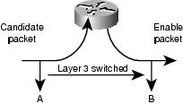
Multilayer switching (MLS) refers to the capability of a switch to forward frames based on information in the Layer 3 (and sometimes Layer 4) header. This usually applies to IP packets, but now it also can occur for IPX packets. The switch learns how to handle these packets by communicating with one or more routers. Using a simplified explanation, the switch watches how the router processes a packet, and then the switch takes over processing future packets in this same flow. Traditionally, switches have been much faster at switching frames than routers, so to have them offload traffic from the router can result in significant speed improvements. If something changes in the network, the router can tell the switch to erase its Layer 3 cache and build it from scratch again as the situation evolves. The protocol used to communicate with the routers is called Multilayer Switching Protocol (MLSP).
How to Learn About These Features
These are just some of the basic features that switches support. More are being added every day. It is important to understand how your switches work, which features you are using, and how those features should work. One of the best places to learn this information about Cisco switches is on Cisco's web site.
Go to www.cisco.com; under the section "Service & Support," select Technical Documents. From here, select Documentation Home Page to find documentation sets for all Cisco products. The "Multilayer LAN Switches" link will lead you to documentation for all Cisco LAN switches. To learn about the features of a switch, read the "Software Configuration Guide" for the particular release of software that you use. The software configuration guides give you background information about what the feature does and what commands to use to configure it on your switch. All this information is free on the web; you do not even need an account for this documentation because it is available to anyone. Some of these configuration guides can be read in an afternoon and are well worth the time spent.
Another part of Cisco's web site is populated by Cisco's Technical Assistance Center (TAC). It is filled with information designed to help you implement, maintain, and troubleshoot your network. Go to the TAC web site at: www.cisco.com/tac; from here, you can select Products Home Page to get detailed support information organized by specific products, or you can go to the Technologies Home Page to get support information on technology (Fast Ethernet, Spanning-Tree Protocol, trunking, and so on). TAC documents and online tools specific to LAN Technologies are here: www.cisco.com/warp/customer/473/. Some of the material on the TAC web site, and, in particular, the online tools, are accessible only to users with a Cisco support contract.
General Switch Troubleshooting Suggestions
Many ways exist by which to troubleshoot a switch. As the features of switches grow, the possible things that can break also increase. If you develop an approach or test plan for troubleshooting, you will be better off in the long run than if you just try a hit-and-miss approach. Here are some general suggestions for making your troubleshooting more effective:
•
•
•
•
Troubleshooting Port Connectivity Problems
If the port doesn't work, nothing works! Ports are the foundation of your switching network. Some ports have special significance because of their location in the network and the amount of traffic that they carry. These ports would include connections to other switches, routers, and servers. These ports can be more complicated to troubleshoot because they often take advantage of special features such as trunking and EtherChannel. The rest of the ports are significant as well because they connect the actual users of the network.
Many things can cause a port to be nonfunctional: hardware issues, configuration issues, and traffic issues. Let's look at these categories a little deeper.
Hardware Issues
This section discusses issues related to general hardware requirements, copper, and fiber.
General
Port functionality requires two working ports connected by a working cable (assuming that it is of the correct type). Most Cisco switches default to having a port in notconnect state, which means that it is currently not connected to anything but is willing to connect. If you connect a good cable to two switch ports in the notconnect state, the link light should become green for both ports, and the port status should be "connected," which means that the port is up as far as Layer 1 is concerned. The following paragraphs point out items to check if Layer 1 is not up.
Check the port status for both ports involved. Make sure that neither port involved in the link is shut down. The administrator could have manually shut down one or both ports. Software inside the switch could have shut down the port because of configuration error conditions (we will expand on this later). If one side is shut down and the other is not, the status on the enabled side will be notconnect (because it does not sense a neighbor on the other side of the wire). The status on the shut-down side would say something like "disable" or "errDisable" (depending on what actually shut down the port). The link will not come up unless both ports are enabled.
When you hook up a good cable (again, assuming that it is of the correct type) between two enabled ports, both ports should show a green link light within a few seconds. Also, the port state should show "connected" in the command-line interface (CLI). At this point, if you do not have link, your problem is limited to three things: the port on one side, the port on the other side, or the cable in the middle. In some cases, other devices are involved: media converters (fiber-to-copper, and so on), or, on Gigabit links, you may have gigabit interface connectors (GBICs). Still, this is a reasonably limited area to search.
Media converters can add noise to a connection or weaken the signal if they are not functioning correctly. They also add extra connectors that can cause problems, so this is another component to debug.
Check for loose connections. Sometimes a cable appears to be seated in the jack, but it actually isn't; unplug the cable and re-insert it. You should also look for dirt or broken or missing pins. Do this for both ports involved in the connection.
The cable could be plugged into the wrong port, which commonly happens. Make sure that both ends of the cable are plugged into the ports where you really want them.
You also can have a link on one side and not on the other. Check both sides for link. A single broken wire can cause this type of problem.
A link light does not guarantee that the cable is fully functional. It may have encountered physical stress that causes it to be functional at a marginal level. Usually you will notice this if the port has lots of packet errors.
To determine whether the cable is the problem, swap it with a known good cable. Don't just swap it with any other cable; make sure that you swap it with a cable that you know is good and is of the correct type.
If this is a very long cable run (underground, across a large campus, for example), then it would be nice to have a sophisticated cable tester. If you do not have a cable tester, you might consider the following:
•
•
•
Copper
Make sure that you have the correct cable for the type of connection you are making. Category 3 cable can be used for 10 MB UTP connections, but Category 5 should be used for 10/100 connections.
A straight-through RJ-45 cable is used for end stations, routers, or servers to connect to a switch or hub. An Ethernet crossover cable is used for switch-to-switch or hub-to-switch connections. Below is the pin-out for an Ethernet crossover cable. Maximum distances for Ethernet or Fast Ethernet copper wires are 100 meters. A good general rule of thumb is that when crossing an OSI layer, such as between a switch and a router, use a straight-through cable; when connecting two devices in the same OSI layer, such as between two routers or two switches, use a crossover cable. For purposes of this rule only, treat a workstation like a router.
Figure 23-1 shows the pinouts required for a switch-to-switch crossover cable.
Figure 23-1 Illustration of the Pinouts Required for a Switch-to-Switch Crossover Cable
Fiber
For fiber, make sure that you have the correct cable for the distances involved and the type of fiber ports being used (single mode, multimode). Make sure that the ports being connected are both single-mode or both multimode ports. Single-mode fiber generally reaches 10 km, and multimode fiber can usually reach 2 km, but the special case of 100BaseFX multimode used in half-duplex mode can go only 400 meters.
For fiber connections, make sure that the transmit lead of one port is connected to the receive lead of the other port, and vice versa; transmit-to-transmit and receive-to-receive will not work.
For gigabit connections, GBICs must be matched on each side of the connection. There are different types of GBICs, depending on the cable and distances involved: short wavelength (SX), long wavelength/long haul (LX/LH), and extended distance (ZX). An SX GBIC needs to connect with an SX GBIC; an SX GBIC will not link with an LX GBIC. Also, some gigabit connections require conditioning cables, depending on the lengths involved. Refer to the GBIC installation notes (for examples, see www.cisco.com/univercd/cc/td/doc/product/lan/cat5000/cnfg_nts/ethernet/5399_01.htm).
If your gigabit link will not come up, check to make sure that the flow control and port negotiation settings are consistent on both sides of the link. There could be incompatibilities in the implementation of these features if the switches being connected are from different vendors. If in doubt, turn off these features on both switches.
Configuration Issues
Another cause of port connectivity issues is incorrect software configuration of the switch. If a port has a solid orange light, it means that software inside the switch shut down the port, either by way of the user interface or by internal processes.
Make sure that the administrator has not shut down the ports involved (as mentioned earlier). The administrator could have manually shut down the port on one side of the link. This link will not come up until you re-enable the port; check the port status.
Some switches, such as the Catalyst 4000/5000/6000, may shut down the port if software processes inside the switch detect an error. When you look at the port status, it will read "errDisable." You must fix the configuration problem and then manually take the port out of errDisable state. Some newer software versions—CatOS 5.4(1) and later—have the capability to automatically re-enable a port after a configurable amount of time spent in the errDisable state. Some of the causes for this errDisable state are listed here:
•
•
•
•
•
•
Another cause of inactive ports occurs when the VLAN to which the ports belong disappears. Each port in a switch belongs to a VLAN. If that VLAN is deleted, then the port will become inactive. Some switches show a steady orange light on each port in which this has happened. If you come to work one day and see hundreds of orange lights, don't panic; it could be that all the ports belonged to the same VLAN and someone accidentally deleted the VLAN to which the ports belong. When you add the VLAN back into the VLAN table, the ports will become active again because a port remembers its assigned VLAN.
If you have a link and the ports show that they are connected, but you cannot communicate with another device, this can be particularly perplexing. It usually indicates a problem above the physical layer: Layer 2 or Layer 3. Try the actions suggested in the next paragraphs.
Check the trunking mode on each side of the link. Make sure that both sides are in the same mode. If you turn the trunking mode to on (as opposed to auto or desirable) for one port, and the other port has the trunking mode set to off, the ports will not be capable of communicating. Trunking changes the formatting of the packet; the ports must be in agreement as to what format they are using on the link, or they will not understand each other.
Make sure that all devices are in the same VLAN. If they are not in the same VLAN, then a router must be configured to allow the devices to communicate.
Make sure that your Layer 3 addressing is correctly configured.
Traffic Issues
In this section, we describe some of the things you can learn by looking at a port's traffic information. Most switches have some way to track the packets going in and out of a port. Commands that generate this type of output on the Catalyst 4000/5000/6000 switches are show port and show mac. Output from these commands on the 4000/5000/6000 switches is described in the switch command references.
Some of these port traffic fields show how much data is being transmitted and received on the port. Other fields show how many error frames are being encountered on the port. If you have a large amount of alignment errors, FCS errors, or late collisions, this may indicate a duplex mismatch on the wire. Other causes for these types of errors may be bad network interface cards or cable problems. If you have a large number of deferred frames, it is a sign that your segment has too much traffic; the switch is not capable of sending enough traffic on the wire to empty its buffers. Consider removing some devices to another segment.
Switch Hardware Failure
If you have tried everything you can think of and the port will not work, there might be faulty hardware.
Sometimes ports are damaged by electrostatic discharge (ESD). You may or may not see any indication of this.
Look at the power-on self-test (POST) results from the switch to see whether any failures are indicated for any part of the switch.
If you see behavior that can be considered "strange," this could indicate hardware problems, but it could also indicate software problems. It is usually easier to reload the software than it is to get new hardware. Try working with the switch software first.
The operating system might have a bug. Loading a newer operating system could fix this. You can research known bugs by reading the release notes for the version of code that you are using or by using Cisco's Bug Navigator tool (www.cisco.com/support/bugtools).
The operating system could have somehow become corrupted. Reloading the same version of the operating system could fix the problem.
If the status light on the switch is flashing orange, this usually means that there is some kind of hardware problem with the port or the module or the switch. The same thing is true if the port or module status indicates "faulty."
Before exchanging the switch hardware, you might try a few things:
•
•
•
•
Troubleshooting Ethernet 10/100-Mb
Half-/Full-Duplex AutonegotiationThis section presents general troubleshooting information and a discussion of techniques for troubleshooting Ethernet autonegotiation.
•
•
Introduction
Autonegotiation is an optional function of the IEEE 802.3u Fast Ethernet standard that enables devices to automatically exchange information over a link about speed and duplex capabilities.
Autonegotiation is targeted at ports, which are allocated to areas where transient users or devices connect to a network. For example, many companies provide shared offices or cubes for account managers and system engineers to use when they are in the office rather than on the road. Each office or cube will have an Ethernet port permanently connected to the office's network. Because it may not be possible to ensure that every user has either a 10-Mb, a 100-Mb Ethernet, or a 10/100-Mb card in their laptops, the switch ports that handle these connections must be capable of negotiating their speed and duplex mode. The alternative would be to provide both a 10-Mb and a 100-Mb port in each office or cube and then label them accordingly.
Autonegotiation should not be used for ports that support network infrastructure devices such as switches and routers, or other nontransient end systems such as servers and printers. Although autonegotiation for speed and duplex is normally the default behavior on switch ports that are capable of it, ports connected to fixed devices should always be configured for the correct behavior rather than allowed to negotiate it. This eliminates any potential negotiation issues and ensures that you always know exactly how the ports should be operating. For example, a 10/100BaseTX Ethernet switch-to-switch link that has been configured for 100 Mb full-duplex will operate only at that speed and mode. There is no possibility for the ports to downgrade the link to a slower speed during a port reset or a switch reset. If the ports cannot operate as configured, they should stop passing any traffic. On the other hand, a switch-to-switch link that has been allowed to negotiate its behavior could end up operating at 10 Mb half-duplex. A nonfunctional link is usually easier to discover than a link that is operational but not operating at the expected speed or mode.
One of the most common causes of performance issues on 10/100-Mb Ethernet links is one port on the link operating at half-duplex mode while the other port is operating at full-duplex mode. This occasionally happens when one or both ports on a link are reset and the autonegotiation process doesn't result in the same configuration for both link partners. It also happens when users reconfigure one side of a link and forget to reconfigure the other side. Many performance-related support calls will be avoided by creating a policy that requires ports for all nontransient devices to be configured for their required behavior and enforcing the policy with adequate change control measures.
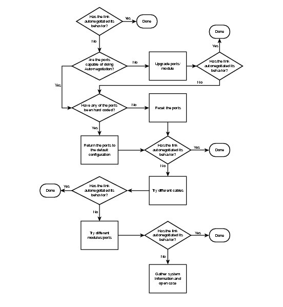
Troubleshooting Ethernet Autonegotiation Between Network Infrastructure Devices
Figure 23-2 show the process you should follow in troubleshooting Ethernet autonegotiation between network infrastructure devices.
Figure 23-2 Troubleshooting Ethernet Autonegotiation
Procedures and Scenarios
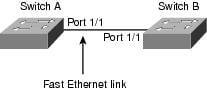
Figure 23-3 shows a scenario using Cat 5k to Cat 5k, using Fast Ethernet.
Figure 23-3 Scenario 1: Cat 5K to Cat 5K, Using Fast Ethernet
Example of Configuring and Troubleshooting Ethernet 10/100-Mb Autonegotiation
This section walks you through examining the behavior of a 10/100-Mb Ethernet port that supports autonegotiation. It will also show how to make changes to its default behavior and how to restore it to the default behavior.
Tasks That Will Be Performed
In this section, you'll perform these tasks:
•
•
•
•
•
•
•
•
•
•
•
•
The following steps are performed on the console of a Catalyst 5K switch.
Step 1
Enter this command for both of the ports that you are troubleshooting. Both ports must support the speed and duplex capabilities shown here if they are supposed to be using autonegotiation.
The italic text in the output shows where the information on the speed and duplex mode capabilities will be found.
Switch-A> (enable) show port capabilities 1/1Model WS-X5530Port 1/1Type 10/100BaseTXSpeed auto,10,100Duplex half,fullStep 2
Switch-A> (enable) set port speed 1/1 autoPort(s) 1/1 speed set to auto detect.Switch-A (enable)
Note
Step 3
Switch-A> (enable) show port 1/1Port Name Status Vlan Level Duplex Speed Type----- ------------------ ---------- ---------- ------ ------ ----- ------------1/1 connected 1 normal a-full a-100 10/100BaseTXSwitch-B> (enable) show port 1/1Port Name Status Vlan Level Duplex Speed Type----- ------------------ ---------- ---------- ------ ------ ----- -----------1/1 connected 1 normal a-full a-100 10/100BaseTXThe italic text in this output shows where the information on the current status of a port can be found. Note that most of the normal output from the show port {mod_num/port_num} command has been omitted.
The "a-" prefixes on the "full" and "100" indicate that this port has not been hard-coded (configured) for a specific duplex mode or speed. Therefore, it is willing to autonegotiate its duplex mode and speed if the device it is connected to (its link partner) is also willing to autonegotiate its duplex mode and speed.
Also note that the status shows "connected" on both ports, which means that a link pulse has been detected from the other port. The status can show "connected" even if duplex has been incorrectly negotiated or misconfigured.
Step 4
Switch-A> (enable) set port speed 1/1 10Port(s) 1/1 speed set to 10Mbps.Switch-A> (enable)
Note
When a port has been configured for a speed, its duplex mode will automatically be configured for the mode that it had previously negotiated—in this case, full duplex. Therefore, entering the set port speed 1/1 10 command caused the duplex mode on port 1/1 to be configured as if the command set port duplex 1/1 full had also been entered. This is explained in the next step.
Step 5
The absence of the "a-" prefix in the status fields of the output from the show port 1/1 command on Switch A shows that the duplex mode is now configured for full-duplex operation, and the speed is now configured for 10 Mb.
Switch-A> (enable) show port 1/1Port Name Status Vlan Level Duplex Speed Type----- ------------------ ---------- ---------- ------ ------ ----- ------------1/1 connected 1 normal full 10 10/100BaseTXStep 6
Switch-B> (enable) show port 1/1Port Name Status Vlan Level Duplex Speed Type----- ------------------ ---------- ---------- ------ ------ ----- ------------1/1 connected 1 normal a-half a-10 10/100BaseTXThis step shows that it is possible for a link partner to detect the speed at which the other link partner is operating, even though the other link partner is not configured for autonegotiation. Sensing the type of electrical signal that is arriving to see if it is 10 Mb or 100 Mb does this. This is how Switch B determined that port 1/1 should be operating at 10 Mb.
It is not possible to detect the correct duplex mode in the same way that the correct speed can be detected. In this case, where Switch B's 1/1 port is configured for autonegotiation and Switch A's is not, Switch B's 1/1 port was forced to select the default duplex mode. On Catalyst Ethernet ports, the default mode is autonegotiate and, if autonegotiation fails, then is half-duplex.
This example also shows that a link can be successfully connected when there is a mismatch in the duplex modes. Port 1/1 on Switch A is configured for full-duplex operation, while port 1/1 on Switch B has defaulted to half-duplex operation. To avoid this, always configure both link partners.
The "a-" prefix on the Duplex and Speed status fields does not always mean that the current behavior was negotiated. Sometimes it means only that the port has not been configured for a speed or duplex mode.
The previous output from Switch B shows the Duplex field as "a-half" and the Speed field as "a-10," which indicates that the port is operating at 10 Mb in half-duplex mode. In this example, however, the link partner on this port (port 1/1 on Switch A) is configured for full-duplex mode and 10 Mb. Therefore, it was not possible for port 1/1 on Switch B to have autonegotiated its current behavior. This proves that the "a-" prefix indicates only a willingness to perform autonegotiation, not that autonegotiation actually took place.
Step 7
%CDP-4-DUPLEXMISMATCH:Full/half duplex mismatch detected o1
It is important to note that this message is created by the Cisco Discovery Protocol (CDP), not the 802.3 autonegotiation protocol. CDP can report problems that it discovers, but it typically doesn't automatically fix them.
A duplex mismatch may or may not result in an error message. Another indication of a duplex mismatch is rapidly increasing FCS and alignment errors on the half-duplex side, and "runts" on the full-duplex port (as seen in a sh port {mod_num/port_num}).
Step 8
%PAGP-5-PORTFROMSTP:Port 1/1 left bridge port 1/1%PAGP-5-PORTTOSTP:Port 1/1 joined bridge port 1/1Step 9
Switch-A> (enable) set port duplex 1/1 halfPort(s) 1/1 set to half-duplex.Switch-A> (enable)The show port 1/1 command shows the change in the duplex mode on this port.
Switch-A> (enable) sh port 1/1Port Name Status Vlan Level Duplex Speed Type----- ------------------ ---------- ---------- ------ ------ ----- ------------1/1 connected 1 normal half 10 10/100BaseTXAt this point, ports 1/1 on both switches are operating at half-duplex mode. Port 1/1 on Switch B, however, is still configured to autonegotiate, as shown in the following output of the show port 1/1 command.
Switch-B> (enable) show port 1/1Port Name Status Vlan Level Duplex Speed Type----- ------------------ ---------- ---------- ------ ------ ----- ------------1/1 connected 1 normal a-half a-10 10/100BaseTXThe next step shows how to configure the duplex mode on port 1/1 in Switch B to half-duplex mode. This is in keeping with the recommended policy of always configuring both link partners in the same way.
Step 10
Here is the output of entering the set port duplex 1/1 half command on Switch B:
Switch-B> (enable) set port duplex 1/1 halfPort 1/1 is in auto-sensing mode.Switch-B> (enable)The set port duplex 1/1 half command failed because this command won't work if autonegotiation is enabled. This also means that this command will not disable autonegotiation. Autonegotiation can be disabled only by using the set port speed {mod_num/port_num {10 | 100}} command.
Here is the output of entering the set port speed 1/1 10 command on Switch B:
Switch-B> (enable) set port speed 1/1 10Port(s) 1/1 speed set to 10 Mbps.Switch-B> (enable)Now the set port duplex 1/1 half command on Switch B will work:
Switch-A> (enable) set port duplex 1/1 halfPort(s) 1/1 set to half-duplex.Switch-A> (enable)The show port 1/1 command on Switch B shows that the ports is now configured for half-duplex mode and 10 Mb.
Switch-B> (enable) show port 1/1Port Name Status Vlan Level Duplex Speed Type----- ------------------ ---------- ---------- ------ ------ ----- ------------1/1 connected 1 normal half 10 10/100BaseTX
Note
Step 11
Switch-A> (enable) set port speed 1/1 autoPort(s) 1/1 speed set to auto detect.Switch-A> (enable)
Note
Step 12
Switch-A> (enable) show port 1/1Port Name Status Vlan Level Duplex Speed Type----- ------------------ ---------- ---------- ------ ------ ----- ------------1/1 connected 1 normal a-full a-100 10/100BaseTXSwitch-B> (enable) show port 1/1Port Name Status Vlan Level Duplex Speed Type----- ------------------ ---------- ---------- ------ ------ ----- ------------1/1 connected 1 normal a-full a-100 10/100BaseTXBoth ports are now set to their default behavior of autonegotiation. Both ports have negotiated full-duplex mode and 100 Mb.
Before Calling Cisco Systems' TAC Team
Before calling Cisco Systems' Technical Assistance Center (TAC), make sure that you have read through this chapter and completed the actions suggested for your system's problem.
Additionally, do the following and document the results so that we can better assist you:
•
•
•
Additional Sources
•
ISL Trunking on Catalyst 5000 and 6000 Family Switches
This section illustrates how to create a switch-to-switch Inter-Switch Link (ISL) trunk. Trunk ports enable connections between switches to carry traffic from more than one virtual local-area network (VLAN). Without trunking, a link between two switches can carry only traffic from one VLAN.
•
•
Introduction
Trunking is not required in very simple switched networks with only one VLAN (broadcast domain). In most LANs, a small portion of traffic is made up of special protocols used for managing the network (Cisco Discovery Protocol, Virtual Trunking Protocol, Dynamic Trunking Protocol, Spanning-Tree Protocol, and Port Aggregation Protocol, to name a few examples). The management VLAN (VLAN 1) is also used when you ping or Telnet directly to or from the switch (this VLAN and the IP address of the switch are defined by configuring the sc0 interface, explained later). In a multi-VLAN environment, many network administrators advocate restricting this management traffic to its own VLAN, normally VLAN 1. User traffic is then configured to flow in VLANs other than this default VLAN.
ISL (Cisco proprietary) is one of two possible trunking protocols for Ethernet. The other protocol is the IEEE 802.1q standard.
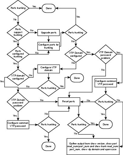
Troubleshooting ISL Trunking on Catalyst 5000 and 6000 Family Switches
This section will walk the reader through some basic ISL trunking scenarios. The reader will learn basic ISL trunking configuration and troubleshooting skills (Figure 23-4).
Figure 23-4 Troubleshooting ISL Trunking on Catalyst 5000 and 6000 Family Switches
Procedures and/or Scenarios
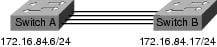
Scenario: Cat 5K to Cat 5K, using Fast Ethernet for ISL trunking (Figure 23-5).
Figure 23-5
Cat 5K to Cat 5K, Using Fast Ethernet for ISL Trunking
Example of Configuring and Troubleshooting ISL Trunking on Catalyst 5000 and 6000 Family Switches
This section walks you through configuring and troubleshooting ISL trunking.
Tasks That Will Be Performed
In this section, you will perform these tasks:
•
•
•
•
•
•
•
•
•
•
•
•
•
Step-by-Step
The following steps are performed on the console of a Catalyst 5K switch.
Step 1
Use the show port capabilities {module_number}|{module_number/port_number} command on both switches to determine whether the ports that you are using support ISL. In this example, note that the port designator 1/1 has been specified at the end of the command. This limits the response to the information directly applicable to port 1/1.
Switch-A> show port capabilities 1/1Model WS-X5530Port 1/1Type 10/100BaseTXSpeed auto,10,100Duplex half,fullTrunk encap type ISLTrunk mode on,off,desirable,auto,nonegotiateChannel 1/1-2Broadcast suppression percentage(0-100)Flow control noSecurity yesMembership static,dynamicFast start yesQOS n/aRewrite noUDLD Not capableSwitch-A>Step 2
Step 3
Switch-A> (enable) show port 1/1Port Name Status Vlan Level Duplex Speed Type----- ------------------ ---------- ---------- ------ ------ ----- ------------1/1 connected 1 normal a-full a-100 10/100BaseTXSwitch-A> (enable)Step 4
Switch-A> (enable) set int sc0 172.16.84.17 255.255.255.0 172.16.84.255Interface sc0 IP address, netmask, and broadcast set.Switch-A> (enable)Step 5
Switch-A> (enable) show trunk 1/1Port Mode Encapsulation Status Native vlan-------- ----------- ------------- ------------ -----------1/1 auto isl not-trunking 1Port Vlans allowed on trunk-------- ---------------------------------------------------------------------1/1 1-1005Port Vlans allowed and active in management domain-------- ---------------------------------------------------------------------1/1 1Port Vlans in spanning tree forwarding state and not pruned-------- ---------------------------------------------------------------------1/1 1Switch-A> (enable)
Note
The trunking status should read "not-trunking" because the default mode for the Dynamic Trunking Protocol (DTP) is Auto. DTP is the strategic replacement for Dynamic ISL (DISL) because it incorporates support for 802.1q trunking negotiation. DTP is available as of version 4.x Catalyst software and certain hardware modules. The following bullets describe the five different states for which DTP can be configured.
•
•
•
•
•
On an individual trunk link, Cisco generally recommends configuring desirable trunking mode on the port nearest the network core, and auto trunking mode on the other side of the link. To hard-code trunking to be enabled, set the trunking mode on both sides to on; you will need to manually set the VLANs to be forwarded across the trunk link (use the full set trunk command) and ensure that the trunk settings are consistent on either side.
Step 6
Switch-A> ping 172.16.84.18172.16.84.18 is aliveSwitch-A>Step 7
Switch-A> (enable) set vlan 2Vlan 2 configuration successfulSwitch-A> (enable)Step 8
Switch-A> (enable) set int sc0 2Interface sc0 vlan set.Switch-A> (enable)Use the show interface command to view the change that you just made. The following output shows this being done on Switch A.
Switch-A> (enable) sh intsl0: flags=51<UP,POINTOPOINT,RUNNING>slip 0.0.0.0 dest 0.0.0.0sc0: flags=63<UP,BROADCAST,RUNNING>vlan 2 inet 172.16.84.17 netmask 255.255.255.0 broadcast 172.16.84.255Switch-A> (enable)Step 9
Switch-A> (enable) ping 172.16.84.18no answer from 172.16.84.18Switch-A> (enable)Step 10
Switch-A> (enable) set vtp domain CookbookVTP domain Cookbook modifiedSwitch-A> (enable)Step 11
Switch-A> (enable) set trunk 1/1 desirablePort(s) 1/1 trunk mode set to desirable.Switch-A> (enable)You should see the following message as ISL becomes active:
1999 Aug 10 15:33:10 %DTP-5-TRUNKPORTON:Port 1/1 has become isl trunkPossible Combinations of DTP Configurations
Table 23-3 shows the 15 possible unique combinations of DTP modes and indicates whether they will result in an active bidirectional trunk. Although it is theoretically possible to trunk in one direction on a link and not the other, it is not recommended.
Before Calling Cisco Systems' TAC Team
Before calling Cisco Systems's Technical Assistance Center (TAC), make sure that you have read through this chapter and completed the actions suggested for your system's problem.
Additionally, do the following and document the results so that we can better assist you:
•
•
•
•
Configuring EtherChannel Switch-to-Switch Connections on Catalyst 4000/5000/6000 Switches
EtherChannel allows multiple physical Fast Ethernet or Gigabit Ethernet links to be combined into one logical channel. This allows load-sharing of traffic among the links in the channel, as well as redundancy in case one or more links in the channel fail. EtherChannel can be used to interconnect LAN switches, routers, servers, and clients via unshielded twisted-pair (UTP) wiring or single-mode and multimode fiber.
EtherChannel is an easy way to aggregate bandwidth between critical networking devices. On the Catalyst 5000, a channel can be created from two ports, making it a 200-Mbps link (400 Mbps full-duplex), or four ports, making it a 400-Mbps link (800 Mbps full-duplex). Some cards and platforms also support Gigabit EtherChannel and have the capability to use from two to eight ports in an EtherChannel. The concept is the same, no matter what speeds or number of links are involved. Normally, the Spanning-Tree Protocol would consider these redundant links between two devices to be loops and would cause the redundant links to be in blocking mode, effectively making these links inactive (providing only backup capabilities in case the main link fails). When using IOS 3.1.1 or greater, Spanning-Tree Protocol treats the channel as one big link, so all the ports in the channel can be active at the same time.
This section takes you through the steps for configuring EtherChannel between two Catalyst 5000 switches and shows you the results of the commands as they are executed. Catalyst 4000 and 6000 switches could have been used in the scenarios presented in this document to obtain the same results. For the Catalyst 2900XL and 1900/2820, the command syntax is different, but the EtherChannel concepts are the same.
EtherChannel may be configured manually by typing in the appropriate commands, or it may be configured automatically by having the switch negotiate the channel with the other side using the Port Aggregation Protocol (PAgP). It is recommended to use PAgP desirable mode to configure EtherChannel whenever possible because manually configuring EtherChannel can create some complications. This section gives examples of configuring EtherChannel manually and examples of configuring EtherChannel by using PAgP. Also included is how to troubleshoot EtherChannel and how to use trunking with EtherChannel. In this chapter, the terms EtherChannel, Fast EtherChannel, Gigabit EtherChannel, and channel will all refer to EtherChannel.
Contents
The following topics will be covered in this section:
•
•
•
•
•
•
Figure 23-6 illustrates our test environment. The configuration of the switches has been cleared using the clear config all command. Then the prompt was changed using set system name. An IP address and mask were assigned to the switch for management purposes using set int sc0 172.16.84.6 255.255.255.0 for Switch A and set int sc0 172.16.84.17 255.255.255.0 for Switch B. A default gateway was assigned to both switches using set ip route default 172.16.84.1.
The switch configurations were cleared so that we could start from the default conditions. The switches were given names so that we can identify them from the prompt on the command line. The IP addresses were assigned so that we can ping between the switches for testing. The default gateway was not used.
Figure 23-6 Test Environment
Many of the commands display more output than is needed for our discussion. Extraneous output will be deleted.
Tasks for Manually Configuring EtherChannel
The following tasks will be performed to manually configure EtherChannel:
•
•
•
•
•
•
Step-by-Step
The following steps will be done from the console of Switch-A and Switch-B:
Step 1
Switch-A show versionWS-C5505 Software, Version McpSW: 4.5(1) NmpSW: 4.5(1)Copyright (c) 1995-1999 by Cisco Systems...Switch-A show moduleMod Module-Name Ports Module-Type Model Serial-Num Status--- ------------------- ----- --------------------- --------- --------- -------1 0 Supervisor III WS-X5530 006841805 ok2 24 10/100BaseTX Ethernet WS-X5225R 012785227 ok...Step 2
Switch-A show port capabilitiesModel WS-X5225RPort 2/1Type 10/100BaseTXSpeed auto,10,100Duplex half,fullTrunk encap type 802.1Q,ISLTrunk mode on,off,desirable,auto,nonegotiateChannel 2/1-2,2/1-4Broadcast suppression percentage(0-100)Flow control receive-(off,on),send-(off,on)Security yesMembership static,dynamicFast start yesRewrite yesSwitch-B show port capabilitiesModel WS-X5234Port 2/1Type 10/100BaseTXSpeed auto,10,100Duplex half,fullTrunk encap type 802.1Q,ISLTrunk mode on,off,desirable,auto,nonegotiateChannel 2/1-2,2/1-4Broadcast suppression percentage(0-100)Flow control receive-(off,on),send-(off,on)Security yesMembership static,dynamicFast start yesRewrite noA port that does not support EtherChannel would look like this:Switch show port capabilitiesModel WS-X5213APort 2/1Type 10/100BaseTXSpeed 10,100,autoDuplex half,fullTrunk encap type ISLTrunk mode on,off,desirable,auto,nonegotiateChannel noBroadcast suppression pps(0-150000)Flow control noSecurity yesMembership static,dynamicFast start yesStep 3
Switch-A show portPort Name Status Vlan Level Duplex Speed Type----- ------------------ ---------- ---------- ------ ------ ----- ------------2/1 notconnect 1 normal auto auto 10/100BaseTX2/2 notconnect 1 normal auto auto 10/100BaseTX2/3 notconnect 1 normal auto auto 10/100BaseTX2/4 notconnect 1 normal auto auto 10/100BaseTXAfter connecting the cables between the two switches, the status is as follows:
1999 Dec 14 20:32:44 %PAGP-5-PORTTOSTP:Port 2/1 joined bridge port 2/11999 Dec 14 20:32:44 %PAGP-5-PORTTOSTP:Port 2/2 joined bridge port 2/21999 Dec 14 20:32:44 %PAGP-5-PORTTOSTP:Port 2/3 joined bridge port 2/31999 Dec 14 20:32:44 %PAGP-5-PORTTOSTP:Port 2/4 joined bridge port 2/4Switch-A show portPort Name Status Vlan Level Duplex Speed Type----- ------------------ ---------- ---------- ------ ------ ----- ------------2/1 connected 1 normal a-full a-100 10/100BaseTX2/2 connected 1 normal a-full a-100 10/100BaseTX2/3 connected 1 normal a-full a-100 10/100BaseTX2/4 connected 1 normal a-full a-100 10/100BaseTXSwitch-B show portPort Name Status Vlan Level Duplex Speed Type----- ------------------ ---------- ---------- ------ ------ ----- ------------2/1 connected 1 normal a-full a-100 10/100BaseTX2/2 connected 1 normal a-full a-100 10/100BaseTX2/3 connected 1 normal a-full a-100 10/100BaseTX2/4 connected 1 normal a-full a-100 10/100BaseTXBecause the switch configurations were cleared before starting this test, the ports are in their default conditions. They are all in vlan1, and their speed and duplex are set to auto. After connecting the cables, they negotiate to a speed of 100 Mbps and full-duplex mode. The status is connected, so we can ping the other switch.
Switch-A ping 172.16.84.17172.16.84.17 is aliveIn your network, you may want to set the speeds manually to 100 Mbps and full-duplex mode instead of relying on autonegotiation because you will probably want your ports to always run at the fastest speed. For a discussion of autonegotiation, see the section "Troubleshooting Ethernet 10-/100-Mb Half-/Full-Duplex Autonegotiation."
Step 4
Step 5
Switch-A show port capabilitiesModel WS-X5225RPort 2/1...Channel 2/1-2,2/1-4Notice that this port can be a part of a group of two (2/1-2) or part of a group of four (2/1-4). An Ethernet Bundling Controller (EBC) on the module causes these configuration limitations. Let's look at another port.
Switch-A show port capabilities 2/3Model WS-X5225RPort 2/3...Channel 2/3-4,2/1-4This port can be grouped into a group of two ports (2/3-4) or into a group of four (2/1-4).
Note
Because we are configuring a group of four ports (2/1-4), this is within the approved grouping. We would not be able to assign a group of four to ports 2/3-6. This is a group of contiguous ports, but they do not start on the approved boundary, as shown by the show port capabilities command (valid groups would be ports 1-4, 5-8, 9-12, 13-16, 17-20, and 21-24).
Step 6
First verify that channeling is off.
Switch-A (enable) show port channelNo ports channellingSwitch-B (enable) show port channelNo ports channellingNow disable the ports on Switch A until both switches have been configured for EtherChannel so that Spanning-Tree Protocol will not generate errors and shut down the ports.
Switch-A (enable) set port disable 2/1-4Ports 2/1-4 disabled.[output from SwitchA upon disabling ports]1999 Dec 15 00:06:40 %PAGP-5-PORTFROMSTP:Port 2/1 left bridg11999 Dec 15 00:06:40 %PAGP-5-PORTFROMSTP:Port 2/2 left bridge port 2/21999 Dec 15 00:06:40 %PAGP-5-PORTFROMSTP:Port 2/3 left bridge port 2/31999 Dec 15 00:06:40 %PAGP-5-PORTFROMSTP:Port 2/4 left bridge port 2/4Turn the channel mode to on for Switch A.
Switch-A (enable) set port channel 2/1-4 onPort(s) 2/1-4 channel mode set to on.Check the status of the channel. Notice that the channel mode has been set to on, but the status of the ports is disabled (because we disabled them earlier). The channel is not operational at this point, but it will become operational when the ports are enabled.
Switch-A (enable) show port channelPort Status Channel Channel Neighbor Neighbormode status device port----- ---------- --------- ----------- ------------------------- ----------2/1 disabled on channel2/2 disabled on channel2/3 disabled on channel2/4 disabled on channel----- ---------- --------- ----------- ------------------------- ----------Because Switch A ports were (temporarily) disabled, Switch B ports no longer have a connection. The following message is displayed on Switch B's console when Switch A ports were disabled.
Switch-B (enable)2000 Jan 13 22:30:03 %PAGP-5-PORTFROMSTP:Port 2/1 left bridge port 2/12000 Jan 13 22:30:04 %PAGP-5-PORTFROMSTP:Port 2/2 left bridge port 2/22000 Jan 13 22:30:04 %PAGP-5-PORTFROMSTP:Port 2/3 left bridge port 2/32000 Jan 13 22:30:04 %PAGP-5-PORTFROMSTP:Port 2/4 left bridge port 2/4Turn on the channel for Switch B.
Switch-B (enable) set port channel 2/1-4 onPort(s) 2/1-4 channel mode set to on.Verify that channel mode is on for Switch B.
Switch-B (enable) show port channelPort Status Channel Channel Neighbor Neighbormode status device port----- ---------- --------- ----------- ------------------------- ----------2/1 notconnect on channel2/2 notconnect on channel2/3 notconnect on channel2/4 notconnect on channel----- ---------- --------- ----------- ------------------------- ----------Notice that the channel mode for Switch B is on, but the status of the ports is notconnect. That is because Switch A ports are still disabled.
Finally, the last step is to enable the ports on Switch A.
Switch-A (enable) set port enable 2/1-4Ports 2/1-4 enabled.1999 Dec 15 00:08:40 %PAGP-5-PORTTOSTP:Port 2/1 joined bridge port 2/1-41999 Dec 15 00:08:40 %PAGP-5-PORTTOSTP:Port 2/2 joined bridge port 2/1-41999 Dec 15 00:08:40 %PAGP-5-PORTTOSTP:Port 2/3 joined bridge port 2/1-41999 Dec 15 00:08:40 %PAGP-5-PORTTOSTP:Port 2/4 joined bridge port 2/1-4Verifying the EtherChannel Configuration
To verify that the channel is set up properly, use the show port channel command.
Switch-A (enable) show port channelPort Status Channel Channel Neighbor Neighbormode status device port----- ---------- --------- ----------- ------------------------- ----------2/1 connected on channel WS-C5505 066509957(Sw 2/12/2 connected on channel WS-C5505 066509957(Sw 2/22/3 connected on channel WS-C5505 066509957(Sw 2/32/4 connected on channel WS-C5505 066509957(Sw 2/4----- ---------- --------- ----------- ------------------------- ----------Switch-B (enable) show port channelPort Status Channel Channel Neighbor Neighbormode status device port----- ---------- --------- ----------- ------------------------- ----------2/1 connected on channel WS-C5505 066507453(Sw 2/12/2 connected on channel WS-C5505 066507453(Sw 2/22/3 connected on channel WS-C5505 066507453(Sw 2/32/4 connected on channel WS-C5505 066507453(Sw 2/4----- ---------- --------- ----------- ------------------------- ----------Spanning-Tree Protocol is shown to treat the ports as one logical port in the following command. In the following output, when the port is listed as 2/1-4, this means that Spanning-Tree Protocol is treating ports 2/1, 2/2, 2/3, and 2/4 as one port.
Switch-A (enable) show spantreeVLAN 1Spanning tree enabledSpanning tree type ieeeDesignated Root 00-10-0d-b2-8c-00Designated Root Priority 32768Designated Root Cost 8Designated Root Port 2/1-4Root Max Age 20 sec Hello Time 2 sec Forward Delay 15 secBridge ID MAC ADDR 00-90-92-b0-84-00Bridge ID Priority 32768Bridge Max Age 20 sec Hello Time 2 sec Forward Delay 15 secPort Vlan Port-State Cost Priority Fast-Start Group-Method--------- ---- ------------- ----- -------- ---------- ------------2/1-4 1 forwarding 8 32 disabled channelEtherChannel can be implemented with different ways of distributing the traffic across the ports in a channel. The EtherChannel specification does not dictate how the traffic should be distributed across the links in a channel. The Catalyst 5000 uses the last bit or the last 2 bits (depending on how many links are in the channel) of the source and destination MAC addresses in the frame to determine which port in the channel to use. You should see similar amounts of traffic on each of the ports in the channel, assuming that traffic is generated by a normal distribution of MAC addresses on one side of the channel. To verify that traffic is going over all the ports in the channel, you can use the show mac command. If your ports were active before configuring EtherChannel, then you may reset the traffic counters to zero by the clear counters command. Then the traffic values will represent how EtherChannel has distributed the traffic.In our test environment, we did not get a real-world distribution because no workstations, servers, or routers are generating traffic. The only devices generating traffic are the switches themselves. We issued some pings from Switch A to Switch B, and you can tell from the following output that the unicast traffic is using the first port in the channel. The Receive information in this case (Rcv-Unicast) shows how Switch B distributed the traffic across the channel to Switch A. A little lower in the output, the Transmit information (Xmit-Unicast) shows how Switch A distributed the traffic across the channel to Switch B. We also see here that a small amount of switch-generated multicast traffic (Dynamic ISL, CDP) goes out all four ports. The broadcast packets are ARP queries (for the default gateway, which doesn't exist in our lab here). If we had workstations sending packets through the switch to a destination on the other side of the channel, we would expect to see traffic going over each of the four links in the channel. You can monitor the packet distribution in your own network using the show mac command.Switch-A (enable) clear countersThis command will reset all MAC and port counters reported in CLI and SNMP.Do you want to continue (y/n) [n]? yMAC and Port counters cleared.Switch-A (enable) show macPort Rcv-Unicast Rcv-Multicast Rcv-Broadcast-------- -------------------- -------------------- --------------------2/1 9 320 1832/2 0 51 02/3 0 47 02/4 0 47 0(...)Port Xmit-Unicast Xmit-Multicast Xmit-Broadcast-------- -------------------- -------------------- --------------------2/1 8 47 1842/2 0 47 02/3 0 47 02/4 0 47 0(...)Port Rcv-Octet Xmit-Octet-------- -------------------- --------------------2/1 35176 174432/2 5304 48512/3 5048 48512/4 5048 4851(...)Last-Time-Cleared--------------------------Wed Dec 15 1999, 01:05:33Using PAgP to Automatically Configure EtherChannel (Preferred Method)
The Port Aggregation Protocol (PAgP) facilitates the automatic creation of EtherChannel links by exchanging packets between channel-capable ports. The protocol learns the capabilities of port groups dynamically and informs the neighboring ports.
When PAgP identifies correctly paired channel-capable links, it groups the ports into a channel. The channel is then added to the spanning tree as a single bridge port. A given outbound broadcast or multicast packet is transmitted out one port in the channel only, not out every port in the channel. In addition, outbound broadcast and multicast packets transmitted on one port in a channel are blocked from returning on any other port of the channel.
Four user-configurable channel modes exist: on, off, auto, and desirable. PAgP packets are exchanged only between ports in auto and desirable modes. Ports configured in on or off modes do not exchange PAgP packets. The recommended settings for switches that you want to form and EtherChannel is to have both switches set to desirable mode. This gives the most robust behavior in case one side encounters error situations or must be reset. The default mode of the channel is auto.
Both the auto and desirable modes allow ports to negotiate with connected ports to determine whether they can form a channel, based on criteria such as port speed, trunking state, native VLAN, and so on.
Ports can form an EtherChannel when they are in different channel modes, as long as the modes are compatible. For example:
•
•
•
•
•
When using EtherChannel, if a "SPANTREE-2: Channel misconfig—x/x-x will be disabled" or similar syslog message is displayed, it indicates a mismatch of EtherChannel modes on the connected ports. We recommend that you correct the configuration and re-enable the ports by entering the set port enable command. Valid EtherChannel configurations include these:
Desirable
Desirable or auto
Auto (default)1
Desirable or auto
On
On
Off
Off
1 If both the local and neighbor ports are in auto mode, an EtherChannel bundle will not form.
Table 23-4 is a summary of all the possible channeling mode scenarios. Some of these combinations may cause the Spanning-Tree Protocol to put the ports on the channeling side into errdisable state (that is, shut them down).
We turned off the channel from the previous example using the following command on Switch A and Switch B:
Switch-A (enable) set port channel 2/1-4 auto
Port(s) 2/1-4 channel mode set to auto.
The default channel mode for a port that is capable of channeling is auto. To verify this, enter the following command:
Switch-A (enable) show port channel 2/1Port Status Channel Channel Neighbor Neighbormode status device port----- ---------- --------- ----------- ------------------------- ----------2/1 connected auto not channelThe previous command also shows that currently the ports are not channeling. Another way to verify the channel state is as follows:
Switch-A (enable) show port channelNo ports channellingSwitch-B (enable) show port channelNo ports channellingTo make the channel work with PAgP is really very simple. At this point, both switches are set to auto mode, which means that they will channel if a connected port sends a PAgP request to channel. Setting Switch A to desirable causes Switch A to send PAgP packets to the other switch, asking it to channel.
Switch-A (enable) set port channel 2/1-4 desirablePort(s) 2/1-4 channel mode set to desirable.1999 Dec 15 22:03:18 %PAGP-5-PORTFROMSTP:Port 2/1 left bridg11999 Dec 15 22:03:18 %PAGP-5-PORTFROMSTP:Port 2/2 left bridge port 2/21999 Dec 15 22:03:18 %PAGP-5-PORTFROMSTP:Port 2/3 left bridge port 2/31999 Dec 15 22:03:18 %PAGP-5-PORTFROMSTP:Port 2/4 left bridge port 2/41999 Dec 15 22:03:19 %PAGP-5-PORTFROMSTP:Port 2/2 left bridge port 2/21999 Dec 15 22:03:19 %PAGP-5-PORTFROMSTP:Port 2/3 left bridge port 2/31999 Dec 15 22:03:20 %PAGP-5-PORTFROMSTP:Port 2/4 left bridge port 2/41999 Dec 15 22:03:23 %PAGP-5-PORTTOSTP:Port 2/1 joined bridge port 2/1-41999 Dec 15 22:03:23 %PAGP-5-PORTTOSTP:Port 2/2 joined bridge port 2/1-41999 Dec 15 22:03:23 %PAGP-5-PORTTOSTP:Port 2/3 joined bridge port 2/1-41999 Dec 15 22:03:24 %PAGP-5-PORTTOSTP:Port 2/4 joined bridge port 2/1-4To view the channel, do as follows:
Switch-A (enable) show port channelPort Status Channel Channel Neighbor Neighbormode status device port----- ---------- --------- ----------- ------------------------- ----------2/1 connected desirable channel WS-C5505 066509957(Sw 2/12/2 connected desirable channel WS-C5505 066509957(Sw 2/22/3 connected desirable channel WS-C5505 066509957(Sw 2/32/4 connected desirable channel WS-C5505 066509957(Sw 2/4----- ---------- --------- ----------- ------------------------- ----------Because Switch B was in auto mode, it responded to the PAgP packets and created a channel with Switch A.
Switch-B (enable)2000 Jan 14 20:26:41 %PAGP-5-PORTFROMSTP:Port 2/1 left bridg12000 Jan 14 20:26:41 %PAGP-5-PORTFROMSTP:Port 2/2 left bridge port 2/22000 Jan 14 20:26:41 %PAGP-5-PORTFROMSTP:Port 2/3 left bridge port 2/32000 Jan 14 20:26:41 %PAGP-5-PORTFROMSTP:Port 2/4 left bridge port 2/42000 Jan 14 20:26:45 %PAGP-5-PORTFROMSTP:Port 2/2 left bridge port 2/22000 Jan 14 20:26:45 %PAGP-5-PORTFROMSTP:Port 2/3 left bridge port 2/32000 Jan 14 20:26:45 %PAGP-5-PORTFROMSTP:Port 2/4 left bridge port 2/42000 Jan 14 20:26:47 %PAGP-5-PORTTOSTP:Port 2/1 joined bridge port 2/1-42000 Jan 14 20:26:47 %PAGP-5-PORTTOSTP:Port 2/2 joined bridge port 2/1-42000 Jan 14 20:26:47 %PAGP-5-PORTTOSTP:Port 2/3 joined bridge port 2/1-42000 Jan 14 20:26:48 %PAGP-5-PORTTOSTP:Port 2/4 joined bridge port 2/1-4Switch-B (enable) show port channelPort Status Channel Channel Neighbor Neighbormode status device port----- ---------- --------- ----------- ------------------------- ----------2/1 connected auto channel WS-C5505 066507453(Sw 2/12/2 connected auto channel WS-C5505 066507453(Sw 2/22/3 connected auto channel WS-C5505 066507453(Sw 2/32/4 connected auto channel WS-C5505 066507453(Sw 2/4----- ---------- --------- ----------- ------------------------- ----------
Note
Switch-B (enable) set port channel 2/1-4 desirablePort(s) 2/1-4 channel mode set to desirable.Switch-B (enable) show port channelPort Status Channel Channel Neighbor Neighbormode status device port----- ---------- --------- ----------- ------------------------- ----------2/1 connected desirable channel WS-C5505 066507453(Sw 2/12/2 connected desirable channel WS-C5505 066507453(Sw 2/22/3 connected desirable channel WS-C5505 066507453(Sw 2/32/4 connected desirable channel WS-C5505 066507453(Sw 2/4----- ---------- --------- ----------- ------------------------- ----------Now if Switch A drops out for some reason, or if new hardware replaces Switch A, then Switch B will try to re-establish the channel. If the new equipment cannot channel, then Switch B will treat its ports 2/1-4 as normal nonchanneling ports. This is one of the benefits of using the desirable mode. If the channel was configured by using the PAgP on mode and one side of the connection has an error of some kind or a reset, it could cause an errdisable state (shutdown) on the other side. With PAgP set in desirable mode on each side. The channel will stabilize and renegotiate the EtherChannel connection.
Trunking and EtherChannel
EtherChannel is independent of trunking. You can turn trunking on, or you can leave trunking off. You also can turn on trunking for all the ports before creating the channel, or you can turn it on after creating the channel (as we will do here). As far as EtherChannel is concerned, it does not matter; trunking and EtherChannel are completely separate features. What does matter is that all the ports involved are in the same mode: Either they are all trunking before you configure the channel, or they are all not trunking before you configure the channel. All the ports must be in the same trunking state before creating the channel.
After a channel is formed, whatever is changed on one port is also changed for the other ports in the channel. The modules used in this test bed can do ISL or 802.1q trunking. By default, the modules are set to auto trunking and negotiate mode, which means that they will trunk if the other side asks them to trunk, and they will negotiate whether to use the ISL or 802.1q method for trunking. If they are not asked to trunk, they will work as normal nontrunking ports.
Switch-A (enable) show trunk 2Port Mode Encapsulation Status Native vlan-------- ----------- ------------- ------------ -----------2/1 auto negotiate not-trunking 12/2 auto negotiate not-trunking 12/3 auto negotiate not-trunking 12/4 auto negotiate not-trunking 1There are a number of different ways to turn on trunking. For this example, we will set Switch A to desirable. Switch A is already set to negotiate. The combination desirable/negotiate will cause Switch A to ask Switch B to trunk and to negotiate the type of trunking to do (ISL or 802.1q). Because Switch B defaults to autonegotiate, Switch B will respond to Switch A's request. The following results occur:
Switch-A (enable) set trunk 2/1 desirablePort(s) 2/1-4 trunk mode set to desirable.Switch-A (enable)1999 Dec 18 20:46:25 %DTP-5-TRUNKPORTON:Port 2/1 has become isl trunk1999 Dec 18 20:46:25 %DTP-5-TRUNKPORTON:Port 2/2 has become isl trunk1999 Dec 18 20:46:25 %PAGP-5-PORTFROMSTP:Port 2/1 left bridge port 2/1-41999 Dec 18 20:46:25 %PAGP-5-PORTFROMSTP:Port 2/2 left bridge port 2/1-41999 Dec 18 20:46:25 %DTP-5-TRUNKPORTON:Port 2/3 has become isl trunk1999 Dec 18 20:46:26 %PAGP-5-PORTFROMSTP:Port 2/3 left bridge port 2/1-41999 Dec 18 20:46:26 %DTP-5-TRUNKPORTON:Port 2/4 has become isl trunk1999 Dec 18 20:46:26 %PAGP-5-PORTFROMSTP:Port 2/4 left bridge port 2/1-41999 Dec 18 20:46:28 %PAGP-5-PORTTOSTP:Port 2/1 joined bridge port 2/1-41999 Dec 18 20:46:29 %PAGP-5-PORTTOSTP:Port 2/2 joined bridge port 2/1-41999 Dec 18 20:46:29 %PAGP-5-PORTTOSTP:Port 2/3 joined bridge port 2/1-41999 Dec 18 20:46:29 %PAGP-5-PORTTOSTP:Port 2/4 joined bridge port 2/1-4Switch-A (enable) show trunk 2Port Mode Encapsulation Status Native vlan-------- ----------- ------------- ------------ -----------2/1 desirable n-isl trunking 12/2 desirable n-isl trunking 12/3 desirable n-isl trunking 12/4 desirable n-isl trunking 1The trunk mode was set to desirable. The result was that trunking mode was negotiated with the neighbor switch, and both decided on ISL (n-isl). The current status now is trunking. The following shows what happened on Switch B because of the command issued on Switch A.
Switch-B (enable)2000 Jan 17 19:09:52 %DTP-5-TRUNKPORTON:Port 2/1 has become isl trunk2000 Jan 17 19:09:52 %DTP-5-TRUNKPORTON:Port 2/2 has become isl trunk2000 Jan 17 19:09:52 %PAGP-5-PORTFROMSTP:Port 2/1 left bridge port 2/1-42000 Jan 17 19:09:52 %DTP-5-TRUNKPORTON:Port 2/3 has become isl trunk2000 Jan 17 19:09:52 %PAGP-5-PORTFROMSTP:Port 2/2 left bridge port 2/1-42000 Jan 17 19:09:53 %DTP-5-TRUNKPORTON:Port 2/4 has become isl trunk2000 Jan 17 19:09:53 %PAGP-5-PORTFROMSTP:Port 2/3 left bridge port 2/1-42000 Jan 17 19:09:53 %PAGP-5-PORTFROMSTP:Port 2/4 left bridge port 2/1-42000 Jan 17 19:09:55 %PAGP-5-PORTTOSTP:Port 2/1 joined bridge port 2/1-42000 Jan 17 19:09:55 %PAGP-5-PORTTOSTP:Port 2/2 joined bridge port 2/1-42000 Jan 17 19:09:55 %PAGP-5-PORTTOSTP:Port 2/3 joined bridge port 2/1-42000 Jan 17 19:09:55 %PAGP-5-PORTTOSTP:Port 2/4 joined bridge port 2/1-4Switch-B (enable) show trunk 2Port Mode Encapsulation Status Native vlan-------- ----------- ------------- ------------ -----------2/1 auto n-isl trunking 12/2 auto n-isl trunking 12/3 auto n-isl trunking 12/4 auto n-isl trunking 1Notice that all four ports (2/1-4) became trunking even though we specifically change only one port (2/1) to desirable. This is an example of how changing one port in the channel affects all the ports.
Troubleshooting EtherChannel
The challenges for EtherChannel can be divided into two main areas: troubleshooting during the configuration phase, and troubleshooting during the execution phase. Configuration errors usually occur because of mismatched parameters on the ports involved (different speeds, different duplex, different spanning-tree port values, and so on). But you can also generate errors during the configuration by setting the channel on one side to on and waiting too long before configuring the channel on the other side. This causes spanning tree loops, which generate an error and shut down the port.
When an error is encountered while configuring EtherChannel, be sure to check the status of the ports after correcting the EtherChannel error situation. If the port status is errdisable, the ports have been shut down by the software, and they will not come on again until you enter the set port enable command.
Note
For the following tests, we will turn off trunking and EtherChannel. The following topics will be covered:
•
•
•
•
Setting Mismatched Parameters
This section examines an example of mismatched parameters. We will set port 2/4 in VLAN 2 while the other ports are still in VLAN 1. To create a new VLAN, we must assign a VTP domain for the switch and then create the VLAN.
Switch-A (enable) show port channelNo ports channellingSwitch-A (enable) show portPort Name Status Vlan Level Duplex Speed Type----- ------------------ ---------- ---------- ------ ------ ----- ------------2/1 connected 1 normal a-full a-100 10/100BaseTX2/2 connected 1 normal a-full a-100 10/100BaseTX2/3 connected 1 normal a-full a-100 10/100BaseTX2/4 connected 1 normal a-full a-100 10/100BaseTXSwitch-A (enable) set vlan 2Cannot add/modify VLANs on a VTP server without a domain name.Switch-A (enable) set vtp domain testDomainVTP domain testDomain modifiedSwitch-A (enable) set vlan 2 name vlan2Vlan 2 configuration successfulSwitch-A (enable) set vlan 2 2/4VLAN 2 modified.VLAN 1 modified.VLAN Mod/Ports---- -----------------------2 2/4Switch-A (enable)1999 Dec 19 00:19:34 %PAGP-5-PORTFROMSTP:Port 2/4 left bridg4Switch-A (enable) show portPort Name Status Vlan Level Duplex Speed Type----- ------------------ ---------- ---------- ------ ------ ----- ------------2/1 connected 1 normal a-full a-100 10/100BaseTX2/2 connected 1 normal a-full a-100 10/100BaseTX2/3 connected 1 normal a-full a-100 10/100BaseTX2/4 connected 2 normal a-full a-100 10/100BaseTXSwitch-A (enable) set port channel 2/1-4 desirablePort(s) 2/1-4 channel mode set to desirable.Switch-A (enable)1999 Dec 19 00:20:19 %PAGP-5-PORTFROMSTP:Port 2/1 left bridge port 2/11999 Dec 19 00:20:19 %PAGP-5-PORTFROMSTP:Port 2/2 left bridge port 2/21999 Dec 19 00:20:19 %PAGP-5-PORTFROMSTP:Port 2/3 left bridge port 2/31999 Dec 19 00:20:20 %PAGP-5-PORTFROMSTP:Port 2/4 left bridge port 2/41999 Dec 19 00:20:20 %PAGP-5-PORTFROMSTP:Port 2/2 left bridge port 2/21999 Dec 19 00:20:22 %PAGP-5-PORTFROMSTP:Port 2/3 left bridge port 2/31999 Dec 19 00:20:22 %PAGP-5-PORTFROMSTP:Port 2/4 left bridge port 2/41999 Dec 19 00:20:24 %PAGP-5-PORTTOSTP:Port 2/1 joined bridge port 2/1-21999 Dec 19 00:20:25 %PAGP-5-PORTTOSTP:Port 2/2 joined bridge port 2/1-21999 Dec 19 00:20:25 %PAGP-5-PORTTOSTP:Port 2/3 joined bridge port 2/31999 Dec 19 00:20:25 %PAGP-5-PORTTOSTP:Port 2/4 joined bridge port 2/4Switch-A (enable) show port channelPort Status Channel Channel Neighbor Neighbormode status device port----- ---------- --------- ----------- ------------------------- ----------2/1 connected desirable channel WS-C5505 066509957(Sw 2/12/2 connected desirable channel WS-C5505 066509957(Sw 2/2----- ---------- --------- ----------- ------------------------- ----------Notice that the channel formed only between ports 2/1 and 2/2. Ports 2/3 and 2/4 were left out because port 2/4 was in a different VLAN. There was no error message; PAgP just did what it could to make the channel work. You need to watch the results when you create the channel to make sure that it did what you wanted it to do.
Now let's set the channel manually to on with port 2/4 in a different VLAN and see what happens. First, we will set the channel mode back to auto to tear down the existing channel, and then we will set the channel manually to on.
Switch-A (enable) set port channel 2/1-4 autoPort(s) 2/1-4 channel mode set to auto.Switch-A (enable)1999 Dec 19 00:26:08 %PAGP-5-PORTFROMSTP:Port 2/1 left bridge port 2/1-21999 Dec 19 00:26:08 %PAGP-5-PORTFROMSTP:Port 2/2 left bridge port 2/1-21999 Dec 19 00:26:08 %PAGP-5-PORTFROMSTP:Port 2/3 left bridge port 2/31999 Dec 19 00:26:08 %PAGP-5-PORTFROMSTP:Port 2/4 left bridge port 2/41999 Dec 19 00:26:18 %PAGP-5-PORTTOSTP:Port 2/1 joined bridge port 2/11999 Dec 19 00:26:19 %PAGP-5-PORTTOSTP:Port 2/2 joined bridge port 2/21999 Dec 19 00:26:19 %PAGP-5-PORTTOSTP:Port 2/3 joined bridge port 2/31999 Dec 19 00:26:19 %PAGP-5-PORTTOSTP:Port 2/4 joined bridge port 2/4Switch-A (enable) show port channelNo ports channellingSwitch-A (enable) set port channel 2/1-4 onMismatch in vlan number.Failed to set port(s) 2/1-4 channel mode to on.Switch-A (enable) show port channelNo ports channellingOn Switch B, we can turn on the channel—notice that it indicates that the ports are channeling fine, but we know that Switch A is not configured correctly.
Switch-B (enable) show port channelNo ports channellingSwitch-B (enable) show portPort Name Status Vlan Level Duplex Speed Type----- ------------------ ---------- ---------- ------ ------ ----- ------------2/1 connected 1 normal a-full a-100 10/100BaseTX2/2 connected 1 normal a-full a-100 10/100BaseTX2/3 connected 1 normal a-full a-100 10/100BaseTX2/4 connected 1 normal a-full a-100 10/100BaseTXSwitch-B (enable) set port channel 2/1-4 onPort(s) 2/1-4 channel mode set to on.Switch-B (enable)2000 Jan 17 22:54:59 %PAGP-5-PORTFROMSTP:Port 2/1 left bridge port 2/12000 Jan 17 22:54:59 %PAGP-5-PORTFROMSTP:Port 2/2 left bridge port 2/22000 Jan 17 22:54:59 %PAGP-5-PORTFROMSTP:Port 2/3 left bridge port 2/32000 Jan 17 22:54:59 %PAGP-5-PORTFROMSTP:Port 2/4 left bridge port 2/42000 Jan 17 22:55:00 %PAGP-5-PORTTOSTP:Port 2/1 joined bridge port 2/1-42000 Jan 17 22:55:00 %PAGP-5-PORTTOSTP:Port 2/2 joined bridge port 2/1-42000 Jan 17 22:55:00 %PAGP-5-PORTTOSTP:Port 2/3 joined bridge port 2/1-42000 Jan 17 22:55:00 %PAGP-5-PORTTOSTP:Port 2/4 joined bridge port 2/1-4Switch-B (enable) show port channelPort Status Channel Channel Neighbor Neighbormode status device port----- ---------- --------- ----------- ------------------------- ----------2/1 connected on channel WS-C5505 066507453(Sw 2/12/2 connected on channel WS-C5505 066507453(Sw 2/22/3 connected on channel WS-C5505 066507453(Sw 2/32/4 connected on channel WS-C5505 066507453(Sw 2/4----- ---------- --------- ----------- ------------------------- ----------This makes it clear that you must check both sides of the channel when manually configuring the channel to make sure that both sides are up, not just one side. The previous output shows that Switch B is set for a channel, but Switch A is not channeling because it has one port that is in the wrong vlan.
Waiting Too Long Before Configuring the Other Side
In our situation, Switch B has EtherChannel turned on, but Switch A does not have EtherChannel turned on because it has a VLAN configuration error (ports 2/1-3 are in VLAN 1, and port 2/4 is in VLAN 2). Here is what happens when one side of a EtherChannel is set to on while the other side is still in auto mode: After a few minutes, Switch B shut down its ports because of a spanning-tree loop detection. This is because Switch B ports 2/1-4 all act like one big port, while Switch A ports 2/1-4 are all totally independent ports. A broadcast sent from Switch B to Switch A on port 2/1 will be sent back to Switch B on ports 2/2, 2/3, and 2/4 because Switch A treats these ports as independent ports. This is why Switch B thinks there is a spanning-tree loop. Notice that the ports on Switch B are now disabled and have a status of errdisable.
Switch-B (enable)2000 Jan 17 22:55:48 %SPANTREE-2-CHNMISCFG: STP loop - channel 2/1-4 is disabled in vlan 1.2000 Jan 17 22:55:49 %PAGP-5-PORTFROMSTP:Port 2/1 left bridge port 2/1-42000 Jan 17 22:56:01 %PAGP-5-PORTFROMSTP:Port 2/2 left bridge port 2/1-42000 Jan 17 22:56:13 %PAGP-5-PORTFROMSTP:Port 2/3 left bridge port 2/1-42000 Jan 17 22:56:36 %PAGP-5-PORTFROMSTP:Port 2/4 left bridge port 2/1-4Switch-B (enable) show port channelPort Status Channel Channel Neighbor Neighbormode status device port----- ---------- --------- ----------- ------------------------- ----------2/1 errdisable on channel2/2 errdisable on channel2/3 errdisable on channel2/4 errdisable on channel----- ---------- --------- ----------- ------------------------- ----------Switch-B (enable) show portPort Name Status Vlan Level Duplex Speed Type----- ------------------ ---------- ---------- ------ ------ ----- ------------2/1 errdisable 1 normal auto auto 10/100BaseTX2/2 errdisable 1 normal auto auto 10/100BaseTX2/3 errdisable 1 normal auto auto 10/100BaseTX2/4 errdisable 1 normal auto auto 10/100BaseTXCorrecting errdisable State
Sometimes when you try to configure EtherChannel but the ports are not configured the same, it will cause the ports on one side of the channel to be shut down. The link lights will be yellow on the port. You can tell this by the console by typing show port. The ports will be listed as errdisable. To recover from this, you should fix the mismatched parameters on the ports involved and then re-enable the ports. Just note that this re-enabling of the ports is a separate step that must be done for the ports to become functional again.
In our example, we know that Switch A had a VLAN mismatch, so we will go to Switch A and put port 2/4 back into VLAN 1. Then we will turn on the channel for ports 2/1-4. Switch A will not show that it's connected until we re-enable Switch B ports. Then when we have fixed Switch A and put it in channeling mode, we will go back to Switch B and re-enable the ports.
Switch-A (enable) set vlan 1 2/4VLAN 1 modified.VLAN 2 modified.VLAN Mod/Ports---- -----------------------1 2/1-24Switch-A (enable) set port channel 2/1-4 onPort(s) 2/1-4 channel mode set to on.Switch-A (enable) sh port channelPort Status Channel Channel Neighbor Neighbormode status device port----- ---------- --------- ----------- ------------------------- ----------2/1 notconnect on channel2/2 notconnect on channel2/3 notconnect on channel2/4 notconnect on channel----- ---------- --------- ----------- ------------------------- ----------Switch-B (enable) show port channelPort Status Channel Channel Neighbor Neighbormode status device port----- ---------- --------- ----------- ------------------------- ----------2/1 errdisable on channel2/2 errdisable on channel2/3 errdisable on channel2/4 errdisable on channel----- ---------- --------- ----------- ------------------------- ----------Switch-B (enable) set port enable 2/1-4Ports 2/1-4 enabled.Switch-B (enable) 2000 Jan 17 23:15:22 %PAGP-5-PORTTOSTP:Port 2/1 joined bridg42000 Jan 17 23:15:22 %PAGP-5-PORTTOSTP:Port 2/2 joined bridge port 2/1-42000 Jan 17 23:15:22 %PAGP-5-PORTTOSTP:Port 2/3 joined bridge port 2/1-42000 Jan 17 23:15:22 %PAGP-5-PORTTOSTP:Port 2/4 joined bridge port 2/1-4Switch-B (enable) show port channelPort Status Channel Channel Neighbor Neighbormode status device port----- ---------- --------- ----------- ------------------------- ----------2/1 connected on channel2/2 connected on channel2/3 connected on channel2/4 connected on channel----- ---------- --------- ----------- ------------------------- ----------Showing What Happens When a Link Breaks and Is Restored
When a port in the channel goes down, then any packets that would normally be sent on that port are shifted over to the next port in the channel. You can verify that this is happening by using the show mac command. In our test bed, we will have Switch A send ping packets to Switch B to see which link the traffic is using. First we will clear the counters and then use show mac, send three pings, and use show mac again to look at which channel the ping responses were received on.
Switch-A (enable) clear countersThis command will reset all MAC and port counters reported in CLI and SNMP.Do you want to continue (y/n) [n]? yMAC and Port counters cleared.Switch-A (enable) show port channelPort Status Channel Channel Neighbor Neighbormode status device port----- ---------- --------- ----------- ------------------------- ----------2/1 connected on channel WS-C5505 066509957(Sw 2/12/2 connected on channel WS-C5505 066509957(Sw 2/22/3 connected on channel WS-C5505 066509957(Sw 2/32/4 connected on channel WS-C5505 066509957(Sw 2/4----- ---------- --------- ----------- ------------------------- ----------Switch-A (enable) show macPort Rcv-Unicast Rcv-Multicast Rcv-Broadcast-------- -------------------- -------------------- --------------------2/1 0 18 02/2 0 2 02/3 0 2 02/4 0 2 0Switch-A (enable) ping 172.16.84.17172.16.84.17 is aliveSwitch-A (enable) ping 172.16.84.17172.16.84.17 is aliveSwitch-A (enable) ping 172.16.84.17172.16.84.17 is aliveSwitch-A (enable) show macPort Rcv-Unicast Rcv-Multicast Rcv-Broadcast-------- -------------------- -------------------- --------------------2/1 3 24 02/2 0 2 02/3 0 2 02/4 0 2 0Now at this point, we have received the ping responses on port 3/1, so when Switch B console sends a response to Switch A, the EtherChannel uses port 2/1. Now we will shut down port 2/1 on Switch B. From Switch A, we will issue another ping and see what channel the response comes back on. (Switch A is sending on the same port to which Switch B is connected. We just show the received packets from Switch B because the transmit packets are farther down in the show mac display.)
1999 Dec 19 01:30:23 %PAGP-5-PORTFROMSTP:Port 2/1 left bridge port 2/1-4Switch-A (enable) ping 172.16.84.17172.16.84.17 is aliveSwitch-A (enable) show macPort Rcv-Unicast Rcv-Multicast Rcv-Broadcast-------- -------------------- -------------------- --------------------2/1 3 37 02/2 1 27 02/3 0 7 02/4 0 7 0Notice that now that port 2/1 is disabled, EtherChannel automatically uses the next port in the channel, 2/2. Now we re-enable port 2/1 and wait for it to join the bridge group; then we issue two more pings.
1999 Dec 19 01:31:33 %PAGP-5-PORTTOSTP:Port 2/1 joined bridge port 2/1-4Switch-A (enable) ping 172.16.84.17172.16.84.17 is aliveSwitch-A (enable) ping 172.16.84.17172.16.84.17 is aliveSwitch-A (enable) show macPort Rcv-Unicast Rcv-Multicast Rcv-Broadcast-------- -------------------- -------------------- --------------------2/1 5 50 02/2 1 49 02/3 0 12 02/4 0 12 0Note that these pings are sent from port 2/1, so when the link comes back up, EtherChannel will again add it to the bundle and use it. All this is done transparently to the user.
Commands Used in This Section
Commands to use for setting the configuration include these:
•
•
•
•
•
•
Commands to use for verifying the configuration include these:
•
•
•
•
•
•
•
•
•
Commands to use for troubleshooting the configuration include these:
•
•
•
•
•
Using PortFast and Other Commands to Fix End-Station Startup Connectivity Problems
If you have workstations connected to switches that either are incapable of logging into your network domain (NT or Novell) or are incapable of getting a DHCP address, then you may want to try the suggestions listed in this document before exploring other avenues. The suggestions are relatively easy to implement and are very often the cause of workstation connectivity problems encountered during the workstation's initialization/startup phase.
With more customers deploying switching to the desktop and replacing their shared hubs with switches, we often see problems introduced in client/server environments because of this initial delay. The biggest problem that we see is that Windows 95/98/NT, Novell, VINES, IBM NetworkStation/IBM Thin Clients, and AppleTalk clients cannot connect to their servers. If the software on these devices is not persistent during the startup procedure, they will give up trying to connect to their server before the switch has even allowed traffic to pass through.
Note
A Microsoft networking client displays "No Domain Controllers Available."
DHCP reports, "No DHCP Servers Available."
A Novell IPX networking workstation does not have the "Novell Login Screen" upon bootup.
An AppleTalk networking client displays "Access to your AppleTalk network has been interrupted. To re-establish your connection, open and close the AppleTalk control panel." It is also possible that the AppleTalk client's Chooser application either will not display a zone list or will display an incomplete zone list.The initial connectivity delay is also frequently seen in a switched environment in which a network administrator updates software or drivers. In this case, a vendor may optimize the drivers so that network initialization procedures happen earlier in the client's startup process (before the switch is ready to process the packets).
With the various features that are now included in some switches, it can take close to a minute for a switch to begin servicing a newly connected workstation. This delay would affect the workstation every time that it is turned on or rebooted. The four main features that cause this delay are listed here:
•
•
•
•
These four features are listed in order of causing the most delay (Spanning-Tree Protocol) to causing the least delay (speed/duplex negotiation). A workstation connected to a switch usually does not cause spanning-tree loops, usually does not need EtherChannel, and usually does not need to negotiate a trunking method. (Disabling link speed/detection negotiation can also reduce port delay, if you need to optimize your startup time as much as possible.)
This section shows how to implement startup speed-optimization commands on three Catalyst switch platforms. In the timing sections, we show how the switch port delay is reduced and by how much.
Contents
The following topics will be covered in this section:
•
•
•
•
•
•
•
•
The terms workstation, end station, and server are all used interchangeably in this section to refer to any device directly connected to a switch by a single NIC card. These terms may also refer to devices with multiple NIC cards in which the NIC card is used only for redundancy—in other words, the workstation or server is not configured to act as a bridge; it just has multiple NIC cards for redundancy.
Note
Background
This section covers four features that some switches have that cause initial delays when a device is connected to a switch. Usually a workstation will either not cause the spanning-tree problem (loops), or not need the feature (PAgP, DTP), so the delay is unnecessary.
Spanning Tree
If you have recently started moving from a hub environment to a switch environment, these connectivity problems may show up because a switch works much differently than a hub. A switch provides connectivity at the data link layer, not at the physical layer. The switch must use a bridging algorithm to decide whether packets received on a port need to be transmitted out other ports. The bridging algorithm is susceptible to physical loops in the network topology. Because of this susceptibility to loops, switches run a protocol called the Spanning-Tree Protocol that causes loops to be eliminated in the topology. Running this protocol causes all ports that are included in the spanning-tree process to become active much slower than they otherwise would because the protocol detects and blocks loops. A bridged network having physical loops, without spanning tree, will break. So, in spite of the time involved, the Spanning-Tree Protocol is a good thing. The spanning-tree process running on Catalyst switches is an industry-standard specification (IEEE 802.1d).
After a port on the switch has a link and joins the bridge group, it will run Spanning-Tree Protocol on that port. A port running a spanning tree can have one of five states: blocking, listening, learning, forwarding, and disabled. The Spanning-Tree Protocol dictates that the port starts out blocking and then immediately moves through the listening and learning phases. By default, it will spend approximately 15 seconds listening and 15 seconds learning.
During the listening state, the switch is trying to determine where it fits in the spanning-tree topology. It especially wants to know whether this port is part of a physical loop. If it is part of a loop, then this port may be chosen to go into blocking mode. Blocking mode means that the port won't send or receive user data for the sake of eliminating loops. If the port is not part of a loop, it will proceed to the learning state, which involves learning which MAC addresses live off this port. This whole spanning-tree initialization process takes about 30 seconds.
If you are connecting a workstation or a server with a single NIC card to a switch port, this connection cannot create a physical loop. These connections are considered leaf nodes. There is no reason to make the workstation wait 30 seconds while the switch checks for loops when the workstation cannot cause a loop. So, Cisco added a feature called PortFast, or Fast-Start, which means that the spanning tree for this port will assume that the port is not part of a loop and will immediately move to the forwarding state, without going through the blocking, listening, or learning states. This can save a lot of time. This command does not turn off the spanning tree. It just makes the spanning tree on the selected port skip a few (unnecessary in this circumstance) steps in the beginning.
Note
EtherChannel
Another feature that a switch may have is called EtherChannel (or Fast EtherChannel, or Gigabit EtherChannel). This feature allows multiple links between the same two devices to work as if they were one fast link, with traffic load balanced among the links. A switch can form these bundles automatically with a neighbor using a protocol called Port Aggregation Protocol (PAgP). Switch ports that can run PAgP usually default to a passive mode called auto, which means that they are willing to form a bundle if the neighbor device across the link asks them to. Running the protocol in auto mode can cause a port to delay for up to 15 seconds before passing control to the spanning-tree algorithm (PAgP runs on a port before spanning tree does). There is no reason to have PAgP running on a port connected to a workstation. Setting the switch port PAgP mode to off will eliminate this delay.
Trunking
Another switch feature is the capability of a port to form a trunk. A trunk is configured between two devices when they need to carry traffic from multiple VLANs. A VLAN is something that switches create to make a group of workstations appear to be on their own segment or broadcast domain. Trunk ports make these VLANs extend across multiple switches so that a single VLAN can cover an entire campus. They do this by adding tags to the packets, indicating which VLAN the packet belongs to.
Different types of trunking protocols exist. If a port can become a trunk, then it may also have the capability to trunk automatically and, in some cases, even negotiate what type of trunking to use on the port. This capability to negotiate the trunking method with the other device is called Dynamic Trunking Protocol (DTP); the precursor to DTP is a protocol called Dynamic ISL (DISL). If these protocols are running, they can delay a port on the switch becoming active.
Usually a port connected to a workstation belongs to only one VLAN and therefore does not need to trunk. If a port has the capability to negotiate the formation of a trunk, it will usually default to the auto mode. If the port is changed to a trunking mode of off, it will further reduce the delay of a switch port becoming active.
Speed and Duplex Negotiation
Just turning on PortFast and turning off PAgP (if present) is usually enough to solve the problem, but if you need to eliminate every possible second, you could also set the port speed and duplex manually on the switch if it is a multispeed port (10/100). Autonegotiation is a nice feature, but turning it off could save you 2 seconds on a Catalyst 5000 (it does not help much on the 2800 or 2900XL).
There can be complications, though, if you turn off autonegotiation on the switch but leave it active on the workstation. Because the switch will not negotiate with the client, the client might not choose the same duplex setting that the switch is using. See the section "Troubleshooting Ethernet 10-/100-Mb Half-/Full-Duplex Autonegotiation," earlier in this chapter, for additional information on the caveats of autonegotiation.
How to Reduce Startup Delay on the Catalyst 4000/5000/6000 Switch
The following five commands show how to turn on PortFast, turn off PAgP negotiation, turn off trunking negotiation (DISL, DTP), and turn off speed/duplex negotiation. The set spantree portfast command can be done on a range of ports at once (set spantree portfast 2/1-12 enable). Usually set port channel must be turned off using a valid group of channel-capable ports. In the case that follows, module 2 has the capability to channel with ports 2/1-2 or with ports 2/1-4, so either of these groups of ports would have been valid to use.
Note
Configuration
Use the following commands to reduce startup delay on the Catalyst 4000/5000/6000 switches.
Switch-A (enable) set spantree portfast 2/1 enableWarning: Spantree port fast start should only be enabled on ports connectedto a single host. Connecting hubs, concentrators, switches, bridges, etc. toa fast start port can cause temporary spanning tree loops. Use with caution.Spantree port 2/1 fast start enabled.Switch-A (enable) set port channel 2/1-2 offPort(s) 2/1-2 channel mode set to off.Switch-A (enable) set trunk 2/1 offPort(s) 2/1 trunk mode set to off.The changes to the configuration will be automatically saved to NVRAM.
Verification
The version of the switch software used in this document is 4.5(1). For the full output of show version and show module, refer to the section "Timing Tests with and Without DTP, PAgP, and PortFast on a Catalyst 5000," later in this chapter.
Switch-A (enable) show version
WS-C5505 Software, Version McpSW: 4.5(1) NmpSW: 4.5(1)
The following command shows how to view the current state of a port with regard to spanning tree. Currently the port is in the spanning tree forwarding state (sending and receiving packets), and the Fast-Start column shows that PortFast is currently disabled. In other words, the port will take at least 30 seconds to move to the forwarding state whenever it initializes.
Switch-A (enable) show port spantree 2/1Port Vlan Port-State Cost Priority Fast-Start Group-Method-------- ---- ------------- ----- -------- ---------- ------------2/1 1 forwarding 19 32 disabledNow we will enable PortFast on this switch port. The switch warns us that this command should be used only on ports that are connected to a single host (a workstation, server, and so on) and are never to be used on ports connected to other hubs or switches. The reason that we enable PortFast is so the port will start forwarding immediately. We can do this because a workstation or server will not cause a network loop, so why waste time checking? But another hub or switch could cause a loop, and we want to always go through the normal listening and learning stages when connecting to these types of devices.
Switch-A (enable) set spantree portfast 2/1 enableWarning: Spantree port fast start should only be enabled on ports connected to a single host. Connecting hubs, concentrators, switches, bridges, etc. toa fast start port can cause temporary spanning tree loops. Use with caution.Spantree port 2/1 fast start enabled.To verify that PortFast is enabled for this port, use the following command:
Switch-A (enable) show port spantree 2/1Port Vlan Port-State Cost Priority Fast-Start Group-Method-------- ---- ------------- ----- -------- ---------- ------------2/1 1 forwarding 19 32 enabledAnother way to view the PortFast settings for one or more ports is to view the spanning-tree information for a specific VLAN. Later, in the section "Timing Tests with and Without DTP, PAgP, and PortFast on a Catalyst 5000," we show how to have the switch report each stage of spanning tree that it moves through in real time. The output that follows also shows the forward delay time (15 seconds), which is how long the spanning tree will be in the listening state and how long it will be in the learning state for each port in the VLAN.
Switch-A (enable) show spantree 1VLAN 1Spanning tree enabledSpanning tree type ieeeDesignated Root 00-e0-4f-94-b5-00Designated Root Priority 8189Designated Root Cost 19Designated Root Port 2/24Root Max Age 20 sec Hello Time 2 sec Forward Delay 15 secBridge ID MAC ADDR 00-90-92-b0-84-00Bridge ID Priority 32768Bridge Max Age 20 sec Hello Time 2 sec Forward Delay 15 secPort Vlan Port-State Cost Priority Fast-Start Group-Method--------- ---- ------------- ----- -------- ---------- ------------2/1 1 forwarding 19 32 enabled...To verify that PAgP is off, use the show port channel command, which follows. Be sure to specify the module number (2, in this case) so that the command will show you the channel mode even if there is no channel formed. If we do show port channel with no channels formed, it just says "no ports channeling." We want to go further and see the current channel mode.
Switch-A (enable) show port channelNo ports channelingSwitch-A (enable) show port channel 2Port Status Channel Channel Neighbor Neighbormode status device port----- ---------- --------- ----------- ------------------------- ----------2/1 notconnect auto not channel2/2 notconnect auto not channel...Switch-A (enable) set port channel 2/1-2 offPort(s) 2/1-2 channel mode set to off.Switch-A (enable) show port channel 2Port Status Channel Channel Neighbor Neighbormode status device port----- ---------- --------- ----------- ------------------------- ----------2/1 connected off not channel2/2 connected off not channel...To verify that trunking negotiation is off, use the set trunk off command. We show the default state here. Then we turn trunking to off and show the resulting state. We specify module number 2 so that we can see the current channel mode for the ports in this module.
Switch-A (enable) show trunk 2Port Mode Encapsulation Status Native vlan-------- ----------- ------------- ------------ -----------2/1 auto negotiate not-trunking 12/2 auto negotiate not-trunking 1...Switch-A (enable) set trunk 2/1-2 offPort(s) 2/1-2 trunk mode set to off.Switch-A (enable) show trunk 2Port Mode Encapsulation Status Native vlan-------- ----------- ------------- ------------ -----------2/1 off negotiate not-trunking 12/2 off negotiate not-trunking 1...We do not show an example here of turning off speed/duplex autonegotiation by manually setting the speed and duplex on the switch; it should not be necessary except in the rarest of cases. We give an example of how to do this in Step 10 of the next section, if you feel that it will be necessary for your situation.
Timing Tests with and Without DTP, PAgP, and PortFast on a Catalyst 5000
The following test shows what happens with switch port initialization timing as the various commands are applied. The default settings of the port are used first to give a benchmark. They have PortFast disabled, PAgP (EtherChannel) mode set to auto (it will channel if asked to channel), and the trunking mode (DTP) set to auto (it will trunk if asked to trunk). The test then proceeds to turn on PortFast and measure the time, then to turn off PAgP and measure the time, and then to turn off trunking and measure the time. Finally, we turn off autonegotiation and measure the time. All these tests will be done on a Catalyst 5000 with a 10/100 Fast Ethernet card that supports DTP and PAgP.
Note
Step 1
Switch-A (enable) show versionWS-C5505 Software, Version McpSW: 4.5(1) NmpSW: 4.5(1)Copyright (c) 1995-1999 by Cisco SystemsNMP S/W compiled on Mar 29 1999, 16:09:01MCP S/W compiled on Mar 29 1999, 16:06:50System Bootstrap Version: 3.1.2Hardware Version: 1.0 Model: WS-C5505 Serial #: 066507453Mod Port Model Serial # Versions--- ---- ---------- --------- ----------------------------------------1 0 WS-X5530 006841805 Hw : 1.3Fw : 3.1.2Fw1: 3.1(2)Sw : 4.5(1)2 24 WS-X5225R 012785227 Hw : 3.2Fw : 4.3(1)Sw : 4.5(1)DRAM FLASH NVRAMModule Total Used Free Total Used Free Total Used Free------ ------- ------- ------- ------- ------- ------- ----- ----- -----1 32640K 13648K 18992K 8192K 4118K 4074K 512K 119K 393KUptime is 28 days, 18 hours, 54 minutesSwitch-A (enable) show moduleMod Module-Name Ports Module-Type Model Serial-Num Status--- ------------------- ----- --------------------- --------- --------- -------1 0 Supervisor III WS-X5530 006841805 ok2 24 10/100BaseTX Ethernet WS-X5225R 012785227 okMod MAC-Address(es) Hw Fw Sw--- -------------------------------------- ------ ---------- -----------------1 00-90-92-b0-84-00 to 00-90-92-b0-87-ff 1.3 3.1.2 4.5(1)2 00-50-0f-b2-e2-60 to 00-50-0f-b2-e2-77 3.2 4.3(1) 4.5(1)Mod Sub-Type Sub-Model Sub-Serial Sub-Hw--- -------- --------- ---------- ------1 NFFC WS-F5521 0008728786 1.0Step 2
Switch-A (enable) show loggingLogging buffer size: 500timestamp option: enabledLogging history size: 1Logging console: enabledLogging server: disabledserver facility: LOCAL7server severity: warnings(4)Facility Default Severity Current Session Severity------------- ----------------------- ------------------------...spantree 2 2...0(emergencies) 1(alerts) 2(critical)3(errors) 4(warnings) 5(notifications)6(information) 7(debugging)We are going to change the level for the spanning-tree to 7 (debug) so we can see the spanning-tree states change on the port. This configuration change lasts only for the terminal session, and then it goes back to normal.
Switch-A (enable) set logging level spantree 7System logging facility <spantree for this session set to severity 7(debugging)Switch-A (enable) show logging...Facility Default Severity Current Session Severity------------- ----------------------- ------------------------...spantree 2 7...Step 3
Switch-A (enable) set port disable 2/1Port 2/1 disabled.Step 4
Switch-A (enable) show timeFri Feb 25 2000, 12:20:17Switch-A (enable) set port enable 2/1Port 2/1 enabled.Switch-A (enable)2000 Feb 25 12:20:39 %PAGP-5-PORTTOSTP:Port 2/1 joined bridge port 2/12000 Feb 25 12:20:39 %SPANTREE-6-PORTBLK: port 2/1 state in vlan 1 changed to blocking.2000 Feb 25 12:20:39 %SPANTREE-6-PORTLISTEN: port 2/1 state in vlane 1 changed to Listening.2000 Feb 25 12:20:53 %SPANTREE-6-PORTLEARN: port 2/1 state in vlan 1 changed to Learning.2000 Feb 25 12:21:08 %SPANTREE-6-PORTFWD: port 2/1 state in vlan 1 changed to forwarding.Notice from the previous output that it took about 22 seconds (20:17 to 20:39) for the port to begin the spanning-tree blocking stage. This time was spent negotiating the link and doing DTP and PAgP stuff. When we started blocking, we are in the spanning-tree realm. From blocking, it went immediately to listening (20:39 to 20:39). From listening to learning took approximately 14 seconds (20:39 to 20:53).
From learning to forwarding took 15 seconds (20:53 to 21:08). So, the total time before the port actually became functional for traffic was about 51 seconds (20:17 to 21:08).
Note
Step 5
Switch-A (enable) show port capabilities 2/1Model WS-X5225RPort 2/1Type 10/100BaseTXSpeed auto,10,100Duplex half,fullTrunk encap type 802.1Q,ISLTrunk mode on,off,desirable,auto,nonegotiateChannel 2/1-2,2/1-4Broadcast suppression percentage(0-100)Flow control receive-(off,on),send-(off,on)Security yesMembership static,dynamicFast start yesRewrite yesSwitch-A (enable) show trunk 2/1Port Mode Encapsulation Status Native vlan-------- ----------- ------------- ------------ -----------2/1 auto negotiate not-trunking 1...Step 6
Switch-A (enable) set port disable 2/1Port 2/1 disabled.Switch-A (enable) set spantree portfast 2/1 enableWarning: Spantree port fast start should only be enabled on ports connectedto a single host. Connecting hubs, concentrators, switches, bridges, etc. toa fast start port can cause temporary spanning-tree loops. Use with caution.Spantree port 2/1 fast start enabled.Switch-A (enable) show timeFri Feb 25 2000, 13:45:23Switch-A (enable) set port enable 2/1Port 2/1 enabled.Switch-A (enable)Switch-A (enable)2000 Feb 25 13:45:43 %PAGP-5-PORTTOSTP:Port 2/1 joined bridgeport 2/12000 Feb 25 13:45:44 %SPANTREE-6-PORTFWD: port 2/1 state in vlan 1 change to forwarding.Now we have a total time of 21 seconds! It takes 20 seconds before it joins the bridge group (45:23 to 45:43). But then, because PortFast is enabled, it only takes 1 second until STP starts forwarding (instead of 30 seconds). We saved 29 seconds by enabling PortFast. Let's see if we can reduce the delay further.
Step 7
Switch-A (enable) show port channel 2/1Port Status Channel Channel Neighbor Neighbormode status device port----- ---------- --------- ----------- ------------------------- ----------2/1 connected auto not channelSwitch-A (enable) set port channel 2/1-2 offPort(s) 2/1-2 channel mode set to off.Step 8
Switch-A (enable) set port disable 2/1Port 2/1 disabled.Switch-A (enable) show timeFri Feb 25 2000, 13:56:23Switch-A (enable) set port enable 2/1Port 2/1 enabled.Switch-A (enable)2000 Feb 25 13:56:32 %PAGP-5-PORTTOSTP:Port 2/1 joined bridgeport 2/12000 Feb 25 13:56:32 %SPANTREE-6-PORTFWD: port 2/1 state in vlan 1 changed to forwarding.Notice here that now it takes only 9 seconds to reach the forwarding state (56:23 to 56:32) instead of 21 seconds, as in the previous test. Turning PAgP from auto to off in this test saved about 12 seconds.
Step 9
Switch-A (enable) set trunk 2/1 offPort(s) 2/1 trunk mode set to off.Switch-A (enable) set port disable 2/1Port 2/1 disabled.Start the test with trunking set to off (instead of auto).
Switch-A (enable) show timeFri Feb 25 2000, 14:00:19Switch-A (enable) set port enable 2/1Port 2/1 enabled.Switch-A (enable)2000 Feb 25 14:00:22 %PAGP-5-PORTTOSTP:Port 2/1 joined bridge port 2/12000 Feb 25 14:00:23 %SPANTREE-6-PORTFWD: port 2/1 state in vlan 1 change for forwarding.We saved a few seconds at the beginning because it took only 4 seconds to reach the spanning-tree forwarding state (00:19 to 00:22). We saved about 5 seconds by changing the trunking mode from auto to off.
Step 10
Setting the speed and duplex manually on our side requires that you set the speed and duplex on the other side as well. This is because setting the port speed and duplex disables autonegotiation on the port, and the connecting device will not see autonegotiation parameters. The connecting device will connect only at half-duplex mode, and the resulting duplex mismatch results in poor performance and port errors. Remember, if you set speed and duplex on one side, you must set speed and duplex on the connecting device as well to avoid these problems.
To view the port status after setting the speed and duplex, use the show port command.
Switch-A (enable) set port speed 2/1 100Port(s) 2/1 speed set to 100 Mbps.Switch-A (enable) set port duplex 2/1 fullPort(s) 2/1 set to full-duplex.Switch-A (enable) show portPort Name Status Vlan Level Duplex Speed Type----- ------------------ ---------- ---------- ------ ------ ----- ------------2/1 connected 1 normal full 100 10/100BaseTX...The timing results are as follows:
Switch-A (enable) show timeFri Feb 25 2000, 140528 EasternSwitch-A (enable) set port enable 2/1Port 2/1 enabled.Switch-A (enable)2000 Feb 25 140529 Eastern -0500 %PAGP-5-PORTTOSTP:Port 2/1 joined bridgeport 2/12000 Feb 25 140530 Eastern -0500 %SPANTREE-6-PORTFWD: port 2/1 state in vlan 1 changed to forwarding.The final result gives a time of 2 seconds (0528 to 0530).
Step 11
A lot of variables are involved in this test (PC initialization, PC software, switch console port responding to requests, and so on), but we just wanted to get some feel for how long it would take to get a response from the PCs point of view. All the tests were from the switches' internal debug message point of view.
How to Reduce Startup Delay on the Catalyst 2900XL/3500XL Switch
The 2900XL and 3500XL models can be configured from a web browser, by SNMP, or by the command-line interface (CLI). We will use the CLI. The following is an example of viewing the spanning-tree state of a port, turning on PortFast and then verifying that it is on. The 2900XL/3500XL does support EtherChannel and trunking, but it does not support dynamic EtherChannel creation (PAgP) or dynamic trunk negotiation (DTP) in the version that we tested (11.2[8.2]SA6), so we have no need to turn them off in this test. Also, after turning on PortFast, the elapsed time for the port to come up is already less than 1 second, so there is not much point in trying to change speed/duplex negotiation settings to speed things up. We hope that 1 second will be fast enough! By default, PortFast is off on the switch ports. The commands to turn on PortFast are discussed next.
Configuration
The following commands will help you reduce startup delay on the Catalyst 2900XL and 3500XL platforms:
2900XL#conf t2900XL(config)#interface fastEthernet 0/12900XL(config-if)#spanning-tree portfast2900XL(config-if)#exit2900XL(config)#exit2900XL#copy run startThis platform is like the router IOS; you must save the configuration (copy run start) if you want it to be permanently saved.
Verification
To verify that PortFast is enabled, use this command:
2900XL#show spanning-tree interface fastEthernet 0/1Interface Fa0/1 (port 13) in Spanning tree 1 is FORWARDINGPort path cost 19, Port priority 128Designated root has priority 8192, address 0010.0db1.7800Designated bridge has priority 32768, address 0050.8039.ec40Designated port is 13, path cost 19Timers: message age 0, forward delay 0, hold 0BPDU: sent 2105, received 1The port is in the portfast modeOr, just look at the switch configuration.
2900XL#show running-configBuilding configuration...Current configuration:!version 11.2...!interface VLAN1ip address 172.16.84.5 255.255.255.0no ip route-cache!interface FastEthernet0/1spanning-tree portfast!interface FastEthernet0/2!...Timing Tests on the Catalyst 2900XL
The following steps show how to measure the effect of using PortFast on the 2900XL switch:
Step 1
Switch#show versionCisco Internetwork Operating System SoftwareIOS (tm) C2900XL Software (C2900XL-C3H2S-M), Version 11.2(8.2)SA6, MAINTENANCE INTERIM SOFTWARECopyright (c) 1986-1999 by cisco Systems, Inc.Compiled Wed 23-Jun-99 16:25 by bobaImage text-base: 0x00003000, data-base: 0x00259AECROM: Bootstrap program is C2900XL boot loaderSwitch uptime is 1 week, 4 days, 22 hours, 5 minutesSystem restarted by power-onSystem image file is "flash:c2900XL-c3h2s-mz-112.8.2-SA6.bin", booted via consolecisco WS-C2924-XL (PowerPC403GA) processor (revision 0x11) with 8192K/1024K bytes of memory.Processor board ID 0x0E, with hardware revision 0x01Last reset from power-onProcessor is running Enterprise Edition SoftwareCluster command switch capableCluster member switch capable24 Ethernet/IEEE 802.3 interface(s)32K bytes of flash-simulated non-volatile configuration memory.Base ethernet MAC Address: 00:50:80:39:EC:40Motherboard assembly number: 73-3382-04Power supply part number: 34-0834-01Motherboard serial number: FAA02499G7XModel number: WS-C2924-XL-ENSystem serial number: FAA0250U03PConfiguration register is 0xFStep 2
2900XL(config)#service timestamps debug uptime2900XL(config)#service timestamps log uptime2900XL#debug spantree eventsSpanning Tree event debugging is on2900XL#show debugGeneral spanning tree:Spanning Tree event debugging is onStep 3
2900XL#conf tEnter configuration commands, one per line. End with CNTL/Z.2900XL(config)#interface fastEthernet 0/12900XL(config-if)#shut2900XL(config-if)#00:31:28: ST: sent Topology Change Notice on FastEthernet0/600:31:28: ST: FastEthernet0/1 - blocking00:31:28: %LINK-5-CHANGED: Interface FastEthernet0/1, changed state to administratively down00:31:28: %LINEPROTO-5-UPDOWN: Line protocol on Interface FastEthernet0/1, changed state to down2900XL(config-if)#exit2900XL(config)#exit2900XL#Step 4
show clockconf tint f0/1no shutStep 5
2900XL#show spanning-tree interface fastEthernet 0/1Interface Fa0/1 (port 13) in Spanning tree 1 is FORWARDINGPort path cost 19, Port priority 128Designated root has priority 8192, address 0010.0db1.7800Designated bridge has priority 32768, address 0050.8039.ec40Designated port is 13, path cost 19Timers: message age 0, forward delay 0, hold 0BPDU: sent 887, received 1[Note: there is no message about being in portfast mode is in this spot...]2900XL#show running-configBuilding configuration......!interface FastEthernet0/1[Note: there is no spanning-tree portfast command under this interface...]!...Step 6
2900XL#show clock*00:27:27.632 UTC Mon Mar 1 19932900XL#conf tEnter configuration commands, one per line. End with CNTL/Z.2900XL(config)#int f0/12900XL(config-if)#no shut2900XL(config-if)#00:27:27: ST: FastEthernet0/1 - listening00:27:27: %LINK-3-UPDOWN: Interface FastEthernet0/1, changed state to up00:27:28: %LINEPROTO-5-UPDOWN: Line protocol on Interface FastEthernet0/1, changed state to up00:27:42: ST: FastEthernet0/1 - learning00:27:57: ST: sent Topology Change Notice on FastEthernet0/600:27:57: ST: FastEthernet0/1 - forwardingTotal time from shutdown until the port started forwarding was 30 seconds (27:27 to 27:57).
Step 7
2900XL#conf tEnter configuration commands, one per line. End with CNTL/Z.2900XL(config)#interface fastEthernet 0/12900XL(config-if)#spanning-tree portfast2900XL(config-if)#exit2900XL(config)#exit2900XL#To verify that PortFast is enabled, use the show spanning-tree interface command. Notice that at the end of the command output, it says that PortFast is enabled.
2900XL#show spanning-tree interface fastEthernet 0/1Interface Fa0/1 (port 13) in Spanning tree 1 is FORWARDINGPort path cost 19, Port priority 128Designated root has priority 8192, address 0010.0db1.7800Designated bridge has priority 32768, address 0050.8039.ec40Designated port is 13, path cost 19Timers: message age 0, forward delay 0, hold 0BPDU: sent 1001, received 1The port is in the portfast modeYou can also see that PortFast is enabled in the configuration output:
2900XL#sh ruBuilding configuration......interface FastEthernet0/1spanning-tree portfast...Step 8
2900XL#show clock*00:23:45.139 UTC Mon Mar 1 19932900XL#conf tEnter configuration commands, one per line. End with CNTL/Z.2900XL(config)#int f0/12900XL(config-if)#no shut2900XL(config-if)#00:23:45: ST: FastEthernet0/1 -jump to forwarding from blocking00:23:45: %LINK-3-UPDOWN: Interface FastEthernet0/1, changed state to up00:23:45: %LINEPROTO-5-UPDOWN: Line protocol on Interface FastEthernet0/1, changed state to upIn this case, the total time was less than 1 second. If port initialization delay on the switch was the problem, then PortFast should solve it.
Remember, the switch does not currently support trunk negotiation, so we do not need to turn it off. Nor does it support PAgP for trunking, so we do not need to turn it off either. The switch does support autonegotiation of speed and duplex, but because the delay is so small, this would not be a reason to turn it off.
Step 9
How to Reduce Startup Delay on the Catalyst 1900/2800 Switch
The 1900/2820 switches call PortFast by another name—they call it "spantree start-forwarding." For the version of software we are running to do our tests (V8.01.05), the switches default to having PortFast enabled on the Ethernet (10-Mbps) ports, and PortFast disabled on the Fast Ethernet (uplink) ports. So, when you use show run to view the configuration, if an Ethernet port says nothing about PortFast, then PortFast is enabled. If it says no spantree start-forwarding in the configuration, then PortFast is disabled. On a Fast Ethernet (100-Mbps) port, the opposite is true: For a Fast Ethernet port, PortFast is on only if the port shows spantree start-forwarding in the configuration.
Configuration
Here is an example of setting PortFast on a Fast Ethernet port. These examples use Enterprise edition software, version 8. The 1900 automatically saves the configuration after changes have been made. Remember, you would not want PortFast enabled on any port that connects to another switch or hub—only if the port attaches to an end station. The configuration is saved automatically to NVRAM.
1900#show versionCisco Catalyst 1900/2820 Enterprise Edition SoftwareVersion V8.01.05Copyright (c) Cisco Systems, Inc. 1993-19981900 uptime is 0day(s) 01hour(s) 10minute(s) 42second(s)cisco Catalyst 1900 (486sxl) processor with 2048K/1024K bytes of memoryHardware board revision is 5Upgrade Status: No upgrade currently in progress.Config File Status: No configuration upload/download is in progress27 Fixed Ethernet/IEEE 802.3 interface(s)Base Ethernet Address: 00-50-50-E1-A4-801900#conf tEnter configuration commands, one per line. End with CNTL/Z1900(config)#interface FastEthernet 0/261900(config-if)#spantree start-forwarding1900(config-if)#exit1900(config)#exit1900#Verification
One way to verify that PortFast is on is to look at the configuration. Remember, a Fast Ethernet port must say that it is on. An Ethernet port has PortFast enabled unless the configuration shows that it is off. In the configuration that follows, interface Ethernet 0/1 has PortFast turned off (you can see the command to turn it off), interface Ethernet 0/2 has PortFast on (you see nothing, which means that it is on), and interface Fast Ethernet 0/26 (port A in the menu system) has PortFast on (you can see the command to turn it on).
1900#show running-configBuilding configuration......!interface Ethernet 0/1no spantree start-forwarding!interface Ethernet 0/2!...!interface FastEthernet 0/26spantree start-forwarding!The easiest way to view the PortFast status is through the menu system. If you select (P) for Port Configuration from the main menu and then select a port, the output will tell you whether port fast mode is enabled. The following output is for port Fast Ethernet 0/26 (which is port "A" on this switch).
Catalyst 1900 - Port A ConfigurationBuilt-in 100Base-FX802.1d STP State: Blocking Forward Transitions: 0----------------------- Settings ---------------------------------------[D] Description/name of port[S] Status of port Suspended-no-linkbeat[I] Port priority (spanning tree) 128 (80 hex)[C] Path cost (spanning tree) 10[H] Port fast mode (spanning tree) Enabled[E] Enhanced congestion control Disabled[F] Full duplex / Flow control Half duplex----------------------- Related Menus ----------------------------------[A] Port addressing [V] View port statistics[N] Next port [G] Goto port[P] Previous port [X] Exit to Main MenuEnter Selection:Timing Tests on the Catalyst 1900
The timing values are harder to verify on a 1900/2820 because of the lack of debugging tools, so we just started a ping from a PC connected to the switch directed to the switch itself. We disconnected and then reconnected the cable, and recorded how long it took for the switch to respond to the ping with PortFast on and with PortFast off. For an Ethernet port with PortFast on (the default state), the PC received a response within 5 to 6 seconds. With PortFast off, the PC received a response in 34 to 35 seconds.
An Additional Benefit to PortFast
There is another spanning-tree-related benefit to using PortFast in your network. Every time a link becomes active and moves to the forwarding state in spanning tree, the switch will send a special spanning-tree packet called a Topology Change Notification (TCN). The TCN notification is passed up to the root of the spanning tree, where it is propagated to all the switches in the VLAN. This causes all the switches to age out their table of MAC addresses using the forward delay parameter, which is usually set to 15 seconds. So, every time a workstation joins the bridge group, the MAC addresses on all the switches will be aged out after 15 seconds instead of the normal 300 seconds.
When a workstation becomes active, it does not really change the topology to any significant degree, so as far as all the switches in the VLAN are concerned, it is unnecessary for them to have to go through the fast aging TCN period. If you turn on PortFast, the switch will not send TCN packets when a port becomes active.
Commands to Use for Verifying That the Configuration Is Working
For the 4000/5000/6000 series, use these commands to verify the configuration:
•
•
•
•
•
•
For the 2900XL/3500XL series, use these commands:
•
•
For the 1900/2800 series, use this command:
•
Use the menu system to view the port status screen.
Commands to Use for Troubleshooting the Configuration
For the 4000/5000/6000 series, use these commands in troubleshooting:
•
•
•
•
•
•
•
•
•
•
•
•
•
•
•
•
For the 2900XL/3500XL series, use these commands:
•
•
•
•
•
•
•
For the 1900/2800 series, use this command:
•
Configuring and Troubleshooting IP Multilayer Switching
This document outlines basic troubleshooting of Multilayer Switching (MLS) for IP. This feature has become a highly desired method of accelerating routing performance through the use of dedicated application-specific integrated circuits (ASICs). Traditional routing is done through a central CPU and software; MLS offloads a significant portion of routing (packet rewrite) to hardware and thus has also been termed switching. MLS and Layer 3 switching are equivalent terms. The NetFlow feature of IOS is distinct and is not covered in this document. MLS also includes support for IPX (IPX MLS) and multicasting (MMLS), but this document will exclusively concentrate on basic MLS IP troubleshooting.
Introduction
As greater demands are placed on networks, the need for greater performance increases. More PCs are being connected to LANs, WANs, and the Internet, and their users require fast access to databases, files/web pages, networked applications, other PCs, and streaming video. To keep connections quick and reliable, networks must be capable of rapidly adjusting to changes and failures and finding the best path, all while remaining as invisible as possible to end users. End users who experience rapid information flow between their PC and server with minimal network slowness are happy ones. Determining the best path is the primary function of routing protocols, and this can be a CPU-intensive process; thus, a significant performance increase is gained by offloading a portion of this function to switching hardware. This is the point of the MLS feature.
There are three major components of MLS: Two of them are the MLS-RP and the MLS-SE. The MLS-RP is the MLS-enabled router, performing the traditional function of routing between subnets/VLANs. The MLS-SE is an MLS-enabled switch, which normally requires a router to route between subnets/VLANs but, with special hardware and software, can handle rewriting of the packet. When a packet transverses a routed interface, nondata portions of the packet are changed (rewritten) as it is carried to its destination, hop by hop.
Confusion can arise here because it seems that a Layer 2 device is taking on a Layer 3 task; actually, the switch is only rewriting Layer 3 information and is "switching" between subnets/VLANs—the router is still responsible for standards-based route calculations and best-path determination. Much of this confusion can be avoided by mentally keeping the routing and switching functions separate, especially when, as is commonly the case, they are contained within the same chassis (as with an internal MLS-RP). Think of MLS as a much more advanced form of route caching, with the cache kept separate from the router on a switch. Both the MLS-RP and the MLS-SE, along with respective hardware and software minimums, are required for MLS.
The MLS-RP can be internal (installed in a switch chassis) or external (connected via a cable to a trunk port on the switch). Examples of internal MLS-RPs are the Route-Switch Module (RSM) and the Route-Switch Feature Card (RSFC), which are installed in a slot or supervisor of a Catalyst 5xxx family member, respectively; the same applies to the Multilayer Switch Feature Card (MSFC) for the Catalyst 6xxx family. Examples of external MLS-RPs include any member of the Cisco 7500, 7200, 4700, 4500, or 3600 series routers. In general, to support the MLS IP feature, all MLS-RPs require a minimum IOS version in the 11.3WA or 12.0WA trains; consult release documentation for specifics. Also, MLS must be enabled for a router to be an MLS-RP.
The MLS-SE is a switch with special hardware. For a member of the Catalyst 5xxx family, MLS requires that the supervisor have a NetFlow Feature Card (NFFC) installed; the Supervisor IIG and IIIG have one by default. In addition, a bare minimum of Catalyst OS 4.1.1 software is required. Note that the 4.x train has "gone General Deployment (GD)"—that is, passed rigorous end-user criteria and field-experience targets for stability—so check Cisco's web site for the latest releases. IP MLS is supported and automatically enabled for Catalyst 6xxx hardware and software with the MSFC/PFC (other routers have MLS disabled by default). Note that IPX MLS and MLS for multicasting may have different hardware and software (IOS and Catalyst OS) requirements. More Cisco platforms do/will support the MLS feature. Also, MLS must be enabled for a switch to be an MLS-SE.
The third major component of MLS is the Multilayer Switching Protocol (MLSP). Because understanding the basics of MLSP gets at the heart of MLS and is essential to performing effective MLS troubleshooting, we will describe MLSP here more in detail. MLSP is utilized by the MLS-RP and the MLS-SE to communicate with one another—tasks include enabling MLS; installing, updating, or deleting flows (cache information); and managing and exporting flow statistics (NetFlow Data Export is covered in other documentation). MLSP also allows the MLS-SE to learn the Media Access Control (MAC, Layer 2) addresses of the MLS-enabled router interfaces, check the flowmask of the MLS-RP (explained later in this chapter), and confirm that the MLS-RP is operational. The MLS-RP sends out multicast "hello" packets every 15 seconds using MLSP; if three of these intervals are missed, then the MLS-SE recognizes that the MLS-RP has failed or that connectivity to it has been lost.
Figure 23-7 illustrates three essentials that must be completed (using MLSP) for a shortcut to be created: the candidate, enabler, and caching steps. The MLS-SE checks for a cached MLS entry; if MLS cache entry and packet information match (a hit), the packet's header is rewritten locally on the switch (a shortcut, or bypassing of the router) instead of being sent on to the router, as would normally happen. Packets that do not match and that are sent on to the MLS-RP are candidate packets—that is, there is a possibility of switching them locally.
After passing the candidate packet through the MLS flowmask (explained later in Step 7) and rewriting the information contained in the packet's header (the data portion is not touched), the router sends it toward the next hop along the destination path. The packet is now called an enabler packet. If the packet returns to the same MLS-SE from which it left, an MLS shortcut is created and placed into the MLS cache. Rewriting for that packet and all similar packets that follow (called a flow) is now done locally by switch hardware instead of by router software. The same MLS-SE must see both the candidate and the enabler packets for a particular flow for an MLS shortcut to be created. (This is why network topology is important to MLS.) Remember, the point of MLS is to allow the communication path between two devices in different VLANs, connected off the same switch, to bypass the router and thus enhance network performance.
Figure 23-7 The Three Essentials That Must Be Completed (Using MLSP) for a Shortcut to Be Created: the Candidate, Enabler, and Caching Steps
By using the flowmask (essentially an access list), the administrator can adjust the degree of similarity of these packets, and thus adjust the scope of the flows: destination address; destination and source addresses; or destination, source, and Layer 4 information. Note that the first packet of a flow always passes through the router; from then on it is locally switched. Each flow is unidirectional—communication between PCs, for example, requires the setup and use of two shortcuts. The main purpose of MLSP is to set up, create, and maintain these shortcuts.
These three components (the MLS-RP, the MLS-SE, and the MLSP) free up vital router resources by allowing other network components to take on some of its functions. Depending on the topology and configuration, MLS provides a simple and highly effective method of increasing network performance in the LAN.
Troubleshooting IP MLS Technology
Figure 23-8 is a flow diagram for basic IP MLS troubleshooting. It is derived from the most common types of MLS-IP cases opened with the Technical Assistance Center (TAC) and faced by our customers and TAC engineers, up to the time that this document was created. MLS is a robust feature, and you should have no problems with it. However, if an issue does arise, the following should help you to resolve the types of IP MLS problems that you might likely face. A few essential assumptions have been made:
•
•
•
•
Warning
Figure 23-8 Flow Diagram for Basic IP MLS Troubleshooting
Step 1
Upgrade the MLS-RP and SE to meet minimum software and hardware requirements. For the MLS-RP, no additional hardware is required. Although MLS can be configured on nontrunked interfaces, the connection to the MLS-SE is generally through VLAN interfaces (as with an RSM) or support trunking (can be configured to carry multiple VLAN information by configuring ISL or 802.1q).
Also, remember that, as of publication time, only members of the 7500, 7200, 4700, 4500, and 3600 router families support MLS externally. Currently, only these external routers and the routers that fit into the Catalyst 5xxx or 6xxx switch families (such as the RSM and RSFC for the Catalyst 5xxx family, and the MSFC for the Catalyst 6xxx family) can be MLS-RPs. The MSFC requires the Policy Feature Card (PFC) as well, both installed on the Catalyst 6xx Supervisor. IP MLS is now a standard feature in IOS 12.0 and later router software. IOS software lower than IOS 12.0 generally requires a special train; for such IP MLS support, install the latest images in IOS 11.3 that have the letters "WA" in their filenames.
For the MLS-SE, a NetFlow Feature Card (NFFC) is required for a member of the Catalyst 5xxx family; this card is installed in the Supervisor module of the Catalyst switch and is included as standard hardware in newer Catalyst 5xxx series Supervisors (since 1999). The NFFC is not supported on the Supervisors I or II and is an option on early Supervisor IIIs. Also, a minimum of 4.1.1 CatOS is required for IP MLS. In contrast, for the Catalyst 6xxx family, the required hardware comes as standard equipment, and IP MLS has been supported since the first CatOS software release, 5.1.1 (in fact, IP MLS is an essential and default ingredient for its high performance). With new platforms and software being released that support IP MLS, it is important to check documentation and release notes, and to generally install the latest release in the lowest train that meets your feature requirements. Always check the release notes and consult with your local Cisco sales office for new MLS support and feature developments.
Commands to check the installed hardware and software are show version on the router, and show module on the switch.
Note
Step 2
It is a basic topology requirement of MLS that the router have a path to each of the VLANs. Remember that the point of MLS is to create a shortcut between two VLANs so that the "routing" between the two end devices can be performed by the switch, thus freeing the router for other tasks. The switch is not actually routing; it is rewriting the frames so that it appears to the end devices that they are talking through the router. If the two devices are in the same VLAN, then the MLS-SE will switch the frame locally without utilizing MLS, as switches do in such a transparently bridged environment, and no MLS shortcut will be created. It is possible to have multiple switches and routers in the network, and even multiple switches along the flow path, but the path between the two end devices for which an MLS shortcut is desired must include a single MLS-RP in that VLAN for that path.
In other words, the flow from source to destination must cross a VLAN boundary on the same MLS-RP, and a candidate and enabler packet pair must be seen by the same MLS-SE for the MLS shortcut to be created. If these criteria are not met, then the packet will be routed normally without the use of MLS. See the documents suggested at the end of this chapter for diagrams and discussions regarding supported and unsupported network topologies.
Step 3
If one is not present, add mls rp ip statements appropriately on the MLS-RP. Except for routers for which IP MLS is automatically enabled (such as the Catalyst 6xxx MSFC), this is a required configuration step. For most MLS-RPs (routers configured for IP MLS), this statement must appear both in the global configuration and under the interface configuration.
Note
Step 4
Several configuration options on the router are not compatible with MLS. These include IP accounting, encryption, compression, IP security, network address translation (NAT), and committed access rate (CAR). For further information, see links regarding IP MLS configuration included at the end of this chapter. Packets traversing a router interface configured with any of these features must be routed normally; no MLS shortcut will be created. For MLS to work, you must disable these features on the MLS-RP interface.
Another important feature that affects MLS is access lists, both input and output. Further information on this option is included in the discussion of flowmasks (Step 7).
Step 5
For MLS to function, the switch must recognize the router as an MLS-RP. Internal MLS-RPs (again, the RSM or RSFC in a Catalyst 5xxx family member, and the MSFC in a Catalyst 6xxx family member) are automatically recognized by the MLS-SE in which they are installed. For external MLS-RPs, you must explicitly inform the switch of the router's address. This address is not actually an IP address, although on external MLS-RPs it is chosen from the list of IP addresses configured on the router's interfaces; it is simply a router ID. In fact, for internal MLS-RPs, the MLS-ID is normally not even an IP address configured on the router. Because internal MLS-RPs are included automatically, it is commonly a loopback address (127.0.0.x). For MLS to function, include on the MLS-SE the MLS-ID found on the MLS-RP.
Use show mls rp on the router to find the MLS-ID, and then configure that ID on the switch using the set mls include <MLS-ID> command. This is a required configuration step when using external MLS-RPs.
Warning
Note
Step 6
MLS requires that MLS components, including the end stations, must be in the same Virtual Trunking Protocol (VTP) domain. VTP is a Layer 2 protocol used for managing VLANs on several Catalyst switches from a central switch; it allows an administrator to create or delete a VLAN on all switches in a domain without having to do so on every switch in that domain. The MLSP, which the MLS-SE and the MLS-RP use to communicate with one another, does not cross a VTP domain boundary. If the network administrator has VTP enabled on the switches (VTP is enabled on Catalyst 5xxx and 6xxx family members by default), use the show vtp domain command on the switch to learn in which VTP domain the MLS-SE has been placed. Except for the Catalyst 6xxx MSFC, on which MLS is essentially a plug-and-play feature, add, in the following steps, the VTP domain to each of the router's MLS interfaces. This will permit MLSP multicasts to move between the MLS-RP and MLS-SE, and therefore allow MLS to function.
In interface configuration mode of the MLS-RP, enter the following commands:
•
•
•
•
•
To change the VTP domain name of the MLS-SE, use the following command at the switch CatOS enable prompt:
set vtp domain name <VTP domain name>
For MLS to work, be sure that VTP is enabled on the switch:
set vtp enable
Step 7
A flowmask is a filter configured by a network administrator that is used by MLS to determine whether a shortcut should be created. Just like an access list, the more detailed the criteria you set up, the deeper into the packet the MLS process must look to verify whether the packet meets those criteria. To adjust the scope of MLS-created shortcuts, the flowmask can be made more or less specific; the flowmask is essentially a "tuning" device.
There are three types of IP MLS modes: destination-ip, destination-source-ip, and full-flow-ip. Destination-ip mode, the default, is in use when no access list is applied to the router's MLS-enabled interface. Source-destination-ip mode is in use when a standard access list is applied, and full-flow-ip is in effect for an extended access list. The MLS mode on the MLS-RP is implicitly determined by the type of access list applied to the interface. By contrast, the MLS mode on the MLS-SE is explicitly configured. By choosing the appropriate mode, you can thus configure MLS so that either only the destination address must match for an MLS shortcut to be created, or both source and destination must match, or even Layer 4 information such as TCP/UDP port numbers must match.
The MLS mode is configurable on both the MLS-RP and the MLS-SE, and in general they must match. However, if either source-destination-ip or full-flow-ip MLS modes are deemed to be required, it is best to configure it on the router by applying the appropriate access list. MLS will always choose the most specific mask, giving the flowmask configured on the MLS-RP precedence over the one found on the MLS-SE. Be careful if you change the MLS mode of the switch from the default destination-ip: You should make sure that it matches the MLS mode on the router for MLS to work. For source-destination-ip and full-flow-ip modes, remember to apply the access list to the appropriate router interface. With no access list applied, even if configured, the MLS mode simply will be destination-ip, the default.
Warning
Note
Note
Step 8
As the previous note mentions, changing a flowmask, clearing the route cache, or globally turning off IP routing will cause a cache purge. Other circumstances can also cause full or many single entry purges, and cause MLS to complain of "Too many moves." There are several forms of this message, but each contains these three words. Aside from what has already been mentioned, the most common cause of this error occurs when the switch learns multiple identical Ethernet Media Access Control (MAC) address within the same VLAN; Ethernet standards do not allow for identical MAC addresses within the same VLAN. If you see this message infrequently, or just a few times in a row, there is no cause for concern. MLS is a robust feature, and the message may be simply caused by normal network events, such as a PC connection being moved between ports, for example. If you see this message continuously for several minutes, however, it is likely a symptom of a more serious issue.
When such a situation arises, its root cause is commonly the presence of two devices with the same MAC address actually connected to a VLAN, or a physical loop within the VLAN (or multiple VLANs, if bridging across these broadcast domains). Use spanning-tree troubleshooting covered in the section "Troubleshooting Spanning-Tree Protocol and Related Design Considerations" found later in this chapter and the hint that follows to find the loop and eliminate it. Also, any rapid topology changes can cause temporary network (and MLS) instability (flapping router interfaces, a bad NIC,and so on).
Tips
Commands or Screen Captures
For descriptions and detailed examples of IP MLS router and switch commands, refer to the excellent documentation listed under the "Additional Sources" section.
Before Calling Cisco Systems' TAC Team
Before calling Cisco Systems's Technical Assistance Center (TAC), make sure you that have read through this chapter and completed the actions suggested for your system's problem.
Additionally, do the following and document the results so that we can better assist you:
•
•
•
•
•
•
•
A clear network topology and dial-in or Telnet access also help considerably in effective problem resolution.
Troubleshooting Spanning-Tree Protocol and Related Design Considerations
Note
The primary function of the Spanning-Tree Algorithm (STA) is to cut loops created by redundant links in bridged networks. The Spanning-Tree Protocol (STP) operates at Layer 2 of the OSI model and, by the means of bridge protocol data units (BPDUs) exchanged between bridges, elects the ports that will eventually forward or block traffic. This protocol can fail in some specific cases, and troubleshooting the resulting situation can be very difficult, depending on the design of the network. We can even say that in this particular area, the most important part of the troubleshooting is done before the problem occurs.
This section is not intended to be a complete LAN design guide, but just a list of recommendations that will help in implementing a safe network as far as bridging is concerned. Assuming knowledge of the protocol itself, we will introduce the following topics:
•
•
•
Spanning-Tree Protocol Failure
A failure in the STA generally leads to a bridging loop (not a spanning-tree loop because you don't need STP to have a loop). Most customers calling the TAC for spanning-tree problems suspect a bug, but experience proves that it is seldom the case. Even if the software is at stake, a bridging loop in an STP environment necessarily comes from a port that should block but that is forwarding traffic.
What can cause a blocked port to go to forwarding? Let's first recall why a port ends up in a blocking state. Each LAN has a single designated bridge. This bridge is responsible for the connectivity of the LAN toward the root bridge.
In Figure 23-9, Bridge B has been elected as the designated bridge, and Bridge C is blocking because it is only providing an alternate path to the root. Why is Bridget C blocking, not Bridge B? This is determined practically by the BPDUs that B and C exchange on the LAN. Here, Bridget B had a better BPDU than Bridge C. Bridge B keeps sending BPDUs advertising its superiority over the other bridges on this LAN. If Bridge C fails to receive these BPDUs for a certain period of time (called the max age—20 seconds, by default), it would start a transition to the forwarding mode.
Figure 23-9 Blocked Port on Bridge C Keeps Receiving BPDUs from Bridge B
Important note: A port must keep receiving superior BPDUs to stay in blocking mode.
The following subsections list the different situations that can lead the STA to fail. Most of these failures are, in fact, related to a massive loss of BPDUs, causing blocked ports to transition to forwarding mode.
Duplex Mismatch
Duplex mismatch on a point-to-point link is a very common configuration error. This occurs especially when one side of the link is hard-coded as full duplex. If you leave the other side in autonegotiation mode, it will end up in half-duplex mode (a port with duplex hard-coded does not negotiate anymore).
The worst-case scenario is when a bridge sending BPDUs is configured for half-duplex operation on a link, whereas its peer is configured for full-duplex mode. In Figure 23-10, the duplex mismatch on the link between bridges A and B can easily lead to a bridging loop. Because Bridge B is configured for full-duplex operation, it does not perform carrier sense when accessing the link. Bridge B will then start sending frames even if Bridge A is already using the link. This is a problem for Bridge A, which detects a collision and runs the back-off algorithm before attempting another transmission of its frame. The result is that, if there is enough traffic from B to A, every single packet (including the BPDUs) sent by Bridge A will be deferred or collisioned and eventually dropped. From an STP point of view, because it does not receive BPDUs from Bridge A anymore, Bridge B has lost its root. This leads Bridge B to unblock its port to Bridge C, hence creating the loop.
Figure 23-10 Bridging Loop Created by a Duplex Mismatch
Unidirectional Link
This is a very frequent cause for a bridging loop. Unidirectional links are often caused by a failure not detected on a fiber link, for instance, or a problem with a transceiver. Anything that can lead a link to stay up while providing a one-way communication is very dangerous as far as STP is concerned. The example shown in Figure 23-11 is very straightforward.
Figure 23-11 Bridging Loop in a Unidirectional Link Scenario
Here, let's suppose that the link between bridges A and B is unidirectional and drops traffic from A to B while transmitting traffic from B to A. Suppose that Bridge B should be blocking. We already mentioned that a port can block only if it receives BPDUs from a bridge that has a better priority. In this case, all these BPDUs coming from Bridge A are lost, and Bridge B eventually forwards traffic, creating a loop. Note that, in this case, if the failure exists at startup, the STP will not converge correctly. This means that rebooting the bridges will have absolutely no effect (whereas it could temporarily help in the previous case).
Cisco introduced the UDLD protocol on high-end switches. This feature is capable of detecting wrong cabling or unidirectional links on Layer 2 and automatically breaks resulting loops by disabling some ports. It is really worth running wherever possible in a bridged environment.
Packet Corruption
Packet corruption can also lead to the same kind of failure. If a link is experiencing a high rate of physical errors, a certain number of consecutive BPDUs could be lost, leading a blocking port to transition to forwarding. This case is rather seldom because STP default parameters are very conservative. The blocking port would need to miss its BPDUs for 50 seconds before transitioning to forwarding, and a single BPDU successfully transmitted would break the loop. This case specially occurs when STP parameters have been adjusted without care (max age reduced, for instance).
Resource Errors
Even on high-end switches that perform most of their switching functions in hardware using specialized Asics, STP is implemented in software. This means that if the CPU of the bridge is overutilized for any reason, it is possible that it lacks resources to send out BPDUs. The STA is generally not very processor-intensive and has priority over other processes. You will see in the upcoming section "Look for Resource Errors" that there are some guidelines that govern the number of instances of STP that a particular platform can handle.
PortFast Configuration Error
PortFast is a feature that you typically will want to enable for a port connected to a host. When the link comes up on this port, the first stages of the STA are skipped and the port directly transitions to the forwarding mode. This can obviously be dangerous when not used correctly. Loops occurs then when moving a cable and should be transient only.
In Figure 23-12, Bridge A is a bridge with port p1 already forwarding and port p2 configured for PortFast. Bridge B is a hub. As soon as the second cable is plugged into Bridge A, p2 goes to forwarding and creates a loop between p1 and p2. This will stop as soon as p1 or p2 receives a BPDU that will put one of these two ports in blocking modes. The problem with that kind of transient loop is that if the looping traffic is very intensive, the bridge may have trouble successfully sending the BPDU that will stop the loop. This can delay the convergence considerably. The latest high-end Catalyst software implements a feature called BPDU guard that will even disable the port if it is configured for PortFast and receives a BPDU.
Figure 23-12 Transient Bridging Loop Because of a Wrong PortFast Configuration
Awkward STP Parameter Tuning and Diameter Issues
We already saw that an aggressive value for the max age parameter and the forward-delay could lead to a very unstable STP. The loss of some BPDUs can then cause a loop to appear. Another issue, not very well known, is related to the diameter of the bridged network. The conservative default values for the STP impose a maximum network diameter of 7. This means that two distinct bridges in the network should not be more than seven bridges away the one to the other. Part of this restriction comes from the Age field BPDUs carry: When a BPDU is propagated from the root bridge toward the leaves of the tree, the Age field is incremented each time that it goes though a bridge. Eventually, when the Age field of a BPDU goes beyond the max age, it is discarded. Typically, this will occur if the root is too far away from some bridges of the network. This issue will affect convergence of the spanning tree.
Software Errors
As mentioned in the introduction to this chapter, the STP is one of the very first features that was implemented in Cisco products. You can expect this feature to be very stable. Only interaction with new features, such as EtherChanneling, caused STP to fail in some very specific cases that have been addressed now. A software bug can be anything, so there is no way of really describing the issue that it could introduce. Let's simply state again that the most dangerous situation would be to ignore some BPDUs or, generally speaking, having a blocking port transitioning to forwarding.
Troubleshooting a Failure
Unfortunately, there is no systematic procedure to troubleshoot an STP issue. This section instead looks like a checklist, recapitulating some of the actions available to you. Most of the indications given here apply to bridging loop troubleshooting. Other failures of the STP leading to a loss of connectivity can be identified using a more conventional way, by exploring the path taken by traffic experiencing a problem.
Note that most of these troubleshooting steps assume connectivity to the different devices of the bridge network. This means having console access. During a bridging loop, for example, you will probably not be able to Telnet.
Use the Diagram of the Network
You need to know some basic things about your network before troubleshooting a bridging loop.
You need to know at least the following:
•
•
•
This knowledge is essential at least for two reasons:
•
•
Identify a Bridging Loop
It used to be that a broadcast storm could have the same effect on the network. Nowadays, with high-speed links and devices providing switching at hardware level, it is nearly impossible that, for instance, a single server brings down a network by broadcasting. The real way of identifying a bridging loop for sure is to capture the traffic on a saturated link and to check that you see similar packets multiple times.
But practically, if all users in a certain bridging domain have connectivity issues at the same time, you can already suspect a bridging loop.
Check the port utilization on your devices and look for abnormal values. See the "Check Port Utilization" upcoming section for additional information.
On the Catalyst switches running a CatOS, you can easily check the overall backplane usage using the show system command. This command is very useful because it not only gives you the current usage of the switch backplane, but it also specifies the peak usage (and its date). An unusual peak utilization shows you whether there has ever been a bridging loop on this device.
Restore Connectivity Quickly and Be Ready for Another Time
Bridging loops have extremely severe consequences on a bridged network. Administrators generally don't have time to look for the reason of the loop and prefer to restore connectivity as soon as possible. If you do this, you will not find the real cause of the issue and need to be ready for the next time that it occurs.
Break the Loop Disabling Ports
The easy way out of a bridging loop is to disable manually every single port that is providing redundancy in the network. If you have been able to identify a part of the network that is more affected, start disabling ports in this area. Even better, if possible, start by disabling ports that should be blocking. Each time you disable a port, check if connectivity is restored in the network as if you are hit by a bridging loop—its effect should stop immediately after you break it. Knowing which disabled port stopped the loop, you can be sure that the failure was located on a redundant path where this port was located. If this port should have been blocking, you have probably found the link on which the failure appeared.
Log STP Events on Devices Hosting Blocked Ports
If you couldn't precisely identify the source of the problem—or, for instance, if the problem is only transient—enable the logging of the STP event on the bridges and switches of the network experiencing the failure. If you want to limit the number of devices to configure, enable this logging at least on devices hosting blocked ports because this is always the transition of a blocked port that creates a loop.
•
•
You can also try to send this output to a syslog device. Unfortunately, when a bridging loop occurs, you seldom can keep connectivity to a syslog server.
Check Ports
As mentioned before, the critical ports to be investigated first are the blocking ports. The next section gives a list of what you can look for on the different ports, with a quick description of the commands to enter for both IOS-based machines and CatOS-based switches.
Check That Blocked Ports Receive BPDUs
Especially on blocked ports and root ports, check that you keep receiving BPDUs periodically. Several issues can lead to a port not receiving packets/BPDUs:
•
•
For CatOS, the show mac <module/port> command will tell you the number of multicast packets that a specific port receives. But the simplest is to use show spantree statistic <modele#/port#> <vlan#>. This command displays the exact number of configuration BPDUs received for the specified port on the specified VLAN (a port can belong to several VLANs, if trunking). See the section "An Additional CatOS Command," later in this chapter, for more information.
Check for Duplex Mismatch
To look for a duplex mismatch, you obviously have to check each side of the point-to-point link.
•
•
Check Port Utilization
We have seen that an interface overloaded can fail to transmit vital BPDUs. A very loaded link is also an indication of a possible bridging loop.
•
•
Check Packet Corruption
IOS—Look for increasing figures in the input errors fields of the show interface command.
CatOS—The command show port <modele#/port#> gives you some details with the Aling-Err, FCS-Err, Xmit-Err, Rcv-Err, and Undersize fields. You will get even more detailed statistics using the show counters <modele#/port#> command.
An Additional CatOS Command
The Catalyst-specific software is richer than the IOS as far as STP troubleshooting is concerned. The command show spantree statistics <modele#/port#> <vlan#> gives very accurate information on a specific port. On suspected ports, run this command and pay special attention to the fields:
•
•
Look for Resource Errors
We have seen that a high CPU utilization can be dangerous for a system running the STA. Here is how to check that the device is not running short of CPU resource:
•
•
The following is a summary of the restrictions that apply to the Catalyst 4000/5000/6000 series:
Disable Unneeded Features
Troubleshooting is a matter of identifying what is currently wrong in the network. In this regard, disabling as many features as possible helps to simplify the network structure and eases the identification of the problem. EtherChanneling, for instance, is an advanced feature that needs STP to logically bundle several different links into a single one. It makes sense to disable this feature during a troubleshooting period. Again, this is just an example, but generally, going to a configuration as simple as possible reduces the troubleshooting effort.
Useful Commands
This section lists useful commands for the Catalyst IOS and the Catalyst OS.
Catalyst IOS Commands
show interface
show spanning-tree
show bridge
show processes cpu
debug spantree
logging buffered
Catalyst OS Commands
show port
show mac
show spantree
show spantree statistics
show spantree blockedports
show spantree summary
show top
show inband/show biga
show system
show counters
set spantree root [secondary]
set spantree uplinkfast
set logging level
set logging buffered
Designing STP to Avoid Trouble
We have seen that the spanning tree can fail in some few circumstances and that troubleshooting the related issues can be quite difficult in a live network. This part introduces some guidelines to reduce the risks associated with the spanning tree.
Know Where the Root Is
It sounds trivial, but very often the information is not available at troubleshooting time. Don't leave the STP to decide which bridge will be root. Depending on the design of the network, you should be able to identify for each VLAN which switch is well suited to be root. Generally, it is good to choose a powerful bridge in the middle of the network. Putting the root bridge in the center of the network, directly connected to the servers and routers, generally reduces the average distance from the clients to the servers and routers.
In Figure 23-13, you can clearly see that if Bridge B is the root, the link from A to C will be blocked on A or C. In this case, hosts connected to switch B can access the server and the router in two hops, and hosts connected to Bridge C in three hops. That makes an average of 2.5 hops.
If Bridge A is the root, the router and the server are reachable in two hops for both hosts connected on B and C. The average distance to them is now two hops.
Figure 23-13 Root Bridge Location Is Important
This example is obvious, but it is the same kind of reasoning that is needed in more complex topologies.
Important note: For each VLAN, hard-code the root bridge and the backup root bridge by reducing the value of the STP priority parameter (or using the set spantree root macro).
Know Where Redundancy Is
Plan the way that your redundant links are organized. Here again, forget about the plug-and-play feature of the STP. Decide which ports will be blocking by turning the cost parameter of the STP. Hopefully, this is usually not necessary if you have a hierarchical design and a well-located root bridge.
Note
In case of accidental bridging loops, knowing exactly where the redundant links are helps you identify the loop and its cause. Knowing where the blocked ports should be also help you to find where the error is coming from (by simple comparison).
Minimize the Number of Blocked Ports
The only critical action taken by STP is blocking ports. A single blocking port transitioning to forwarding by error can meltdown a big part of the network. A good way to limit the risk implied by the use of the STP is to reduce the number of blocked ports as much as possible.
Prune VLANs That Are Not Used
You don't need more than two redundant links between two nodes in a bridged network. However, a configuration like that shown in Figure 23-14 frequently appears.
Figure 23-14 Typical Network Design with VLANs Spanning Too Many Links
This is a very common design. Distribution switches are dual-attached to two core switches. Users connected on distribution switches are in only a subset of the VLANs available in the network (here, users connected on Dist2 are all in VLAN 2; Dist3 connects only users in VLAN 3). By default, trunks carry all the VLANs defined in the VTP domain. Now only is Dist2 receiving unnecessary broadcast and multicast traffic for VLAN 3, but it is also blocking one of its ports for VLAN 3. The result is that there are three redundant paths between Core A and Core B. This means more blocked ports and increased chances for a loop.
Important note: Prune any VLAN not needed off your trunks.
VTP pruning can help doing this, but that kind of plug-and-play feature is not really needed in the core of the network.
Let's take the same example as previously shown in Figure 23-14. This time, we just use an access VLAN to connect the distribution switches to the core, as shown in Figure 23-15.
Figure 23-15 Pruning VLANs Already Reduces the Number of Blocked Ports and Avoids Unnecessary Flooding
In this design, we have only one port blocked per VLAN. Note also that with this design, it is possible to remove all redundant links in just one step by shutting down Core A or Core B.
Use Layer 3 Switching
Layer 3 switching means approximately routing at the speed of switching. A router performs two main functions:
1.
2.
High-end Cisco Layer 3 switches now can perform this second function, at the same speed as Layer 2 switching function. There is no speed penalty in introducing a routing hop and creating an additional segmentation of the network. Figure 23-16 illustrates this, using the same diagram structure.
Figure 23-16 Layer 3 Switching Makes a Design with No Blocking Port Possible
In Figure 23-16, Core A and Core B are now some Layer 3 switches. Note that we are not bridging any more VLAN 2 and VLAN 3 between Core A and Core B; thus, we no longer have a loop to cut by the ways of the STP.
•
•
•
The only drawback is that migrating to that kind of design generally implies a rework of the addressing scheme.
Keep STP Even If It Is Not Needed
Even if you have succeeded in removing all the blocked ports of your network, and even if you don't have any physical redundancy, it is safer to keep STP enabled. STP is generally not too processor-intensive (and, anyway, CPU is not involved in packet switching in most Cisco switches), and the few BPDUs sent on each link do not significantly reduce the available bandwidth. On the other end, a bridged network without STP can melt down in a fraction of second if an operator makes an error on a patch panel, for instance. Generally, disabling the STP in a bridged network is not worth the risk.
Keep Traffic Off the Administrative VLAN, and Avoid Having a Single VLAN Spanning the Entire Network
Keeping traffic of the administration VLAN and avoiding having a single VLAN spanning the entire network are related points.
A Cisco switch typically has a single IP address bound to a VLAN (which is often called the administrative VLAN). In this VLAN, the switch is behaving like a generic IP host. In particular, every single broadcast/multicast packet will be forwarded to the CPU. Having a high rate of broadcast/multicast on the administrative VLAN can hit the CPU and impact its capability to process vital BPDUs. Therefore, it is always a good idea to keep user traffic off the administrative VLAN.
Until recently, in a Cisco implementation, there was no way to remove VLAN 1 from a trunk. This VLAN is generally used as an administrative VLAN, where all switches are accessible in the same IP subnet. Although useful, this may be dangerous because a bridging loop on VLAN 1 will affect all trunks and will probably bring the whole network down. Of course, the same problem exists whatever the VLAN is. If possible, try to segment the bridging domains using high-speed Layer 3 switches.
As of version 5.4, the CatOS software allows the clearing of VLAN 1 on trunks (in fact, VLAN 1 still exists but blocks traffic, thus preventing any loop possibility).
Avoid Tuning STP Parameters
Take special care if you plan to change STP timers from their default values. (Another option is to use CatOS macros.) Trying to get faster reconvergence from this, for instance, is very dangerous because it has implications on the diameter of the network and the stability of the STP. The only parameters that you may want to change are the bridge priority (to select the root bridge) and the port cost or priority (to control redundancy and load balancing).
Cisco Catalyst software provides you with macros that will finely tune most important STP parameters for you:
•
•
Configure UDLD When Possible
In case of a unidirectional link occurring on a link with a blocked port, you have a 50 percent chance of a bridging loop. This is the most dangerous possibility of STP failure because the algorithm is not capable of handling this situation. The latest Catalyst software implements the Uni-Directional Link Detection (UDLD) feature that helps to detect this dangerous condition. This works on point-to-point links between Cisco devices only.
Additional Sources
For further information, including step-by-step configuration materials and full command examples for both the IP MLS-RP and the MLS-SE, you are highly encouraged to view the following (log in to maximize the amount of material that you can view):
•
•
•
•
•
•