Downloads |
 Feedback Feedback
|
Table Of Contents
Troubleshooting Frame Relay Connections
Frame Relay: Frame Relay Link Is Down
Frame Relay: Cannot ping Remote Router
Frame Relay: Cannot ping End to End
Troubleshooting Frame Relay Connections
Frame Relay was originally conceived as a protocol for use over ISDN interfaces. Initial proposals to this effect were submitted to the International Telecommunication Union Telecommunication Standardization Sector (ITU-T), formerly the Consultative Committee for International Telegraph and Telephone (CCITT), in 1984. Work on Frame Relay was also undertaken in the American National Standards Institute (ANSI)-accredited T1S1 standards committee in the United States.
A major development in Frame Relay's history occurred in 1990 when Cisco Systems, StrataCom, Northern Telecom, and Digital Equipment Corporation formed a consortium to focus Frame Relay technology development and to accelerate the introduction of interoperable Frame Relay products. This consortium developed a specification conforming to the basic Frame Relay protocol being discussed in T1S1 and ITU-T, but it extended it with features that provide additional capabilities for complex internetworking environments. These Frame Relay extensions are referred to collectively as the Local Management Interface (LMI).
Frame Relay Technology Basics
Frame Relay provides a packet-switching data communications capability that is used across the interface between user devices (for example, routers, bridges, and host machines) and network equipment (for example, switching nodes). User devices are often referred to as data terminal equipment (DTE), whereas network equipment that interfaces to DTE is often referred to as data circuit-terminating equipment (DCE). The network providing the Frame Relay interface can be either a carrier-provided public network or a network of privately owned equipment serving a single enterprise.
As an interface to a network, Frame Relay is the same type of protocol as X.25 (see Chapter 19, "Troubleshooting X.25 Connections"). However, Frame Relay differs significantly from X.25 in its functionality and format. In particular, Frame Relay is a more streamlined protocol, facilitating higher performance and greater efficiency.
As an interface between user and network equipment, Frame Relay provides a means for statistically multiplexing many logical data conversations (referred to as virtual circuits) over a single physical transmission link. This contrasts with systems that use time-division multiplexing (TDM) techniques for supporting multiple data streams. Frame Relay's statistical multiplexing provides more flexible and efficient use of available bandwidth. It can be used without TDM techniques or on top of channels provided by TDM systems.
Another important characteristic of Frame Relay is that it exploits the recent advances in wide-area network (WAN) transmission technology. Earlier WAN protocols such as X.25 were developed when analog transmission systems and copper media were predominant. These links are much less reliable than the fiber media/digital transmission links available today. Over links such as these, link-layer protocols can forgo time-consuming error correction algorithms, leaving these to be performed at higher protocol layers. Greater performance and efficiency is therefore possible without sacrificing data integrity. Frame Relay is designed with this approach in mind. It includes a cyclic redundancy check (CRC) algorithm for detecting corrupted bits (so that the data can be discarded), but it does not include any protocol mechanisms for correcting bad data (for example, by retransmitting it at this level of protocol).
Another difference between Frame Relay and X.25 is the absence of explicit, per-virtual-circuit flow control in Frame Relay. Now that many upper-layer protocols are effectively executing their own flow control algorithms, the need for this functionality at the link layer has diminished. Frame Relay, therefore, does not include explicit flow control procedures that duplicate those in higher layers. Instead, very simple congestion notification mechanisms are provided to allow a network to inform a user device that the network resources are close to a congested state. This notification can alert higher-layer protocols that flow control may be needed.
Current Frame Relay standards address permanent virtual circuits (PVCs) that are administratively configured and managed in a Frame Relay network. Another type, switched virtual circuits (SVCs), has also been proposed. The Integrated Services Digital Network (ISDN) signaling protocol is proposed as the means by which DTE and DCE can communicate to establish, terminate, and manage SVCs dynamically.
LMI Extensions
In addition to the basic Frame Relay protocol functions for transferring data, the consortium Frame Relay specification includes LMI extensions that make supporting large, complex internetworks easier. Some LMI extensions are referred to as "common" and are expected to be implemented by everyone who adopts the specification. Other LMI functions are referred to as "optional." A summary of the LMI extensions follows:
•
Virtual circuit status messages (common)—Provide communication and synchronization between the network and the user device, periodically reporting the existence of new PVCs and the deletion of already existing PVCs, and generally provide information about PVC integrity. Virtual circuit status messages prevent the sending of data into black holes—that is, over PVCs that no longer exist.
•
•
•
Frame Format
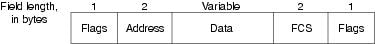
The Frame Relay frame is shown in Figure 18-1. The Flags fields delimit the beginning and end of the frame. Following the leading Flags field are 2 bytes of address information. Ten bits of these 2 bytes make up the actual circuit ID (called the DLCI, for data link connection identifier).
Figure 18-1 The Frame Relay Frame
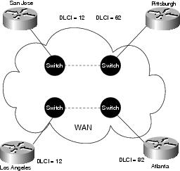
The 10-bit DLCI value is the heart of the Frame Relay header. It identifies the logical connection that is multiplexed into the physical channel. In the basic (not extended by the LMI) mode of addressing, DLCIs have local significance; that is, the end devices at two different ends of a connection may use a different DLCI to refer to that same connection. Figure 18-2 provides an example of the use of DLCIs in nonextended Frame Relay addressing.
Figure 18-2 Frame Relay Addressing
In Figure 18-2, assume two PVCs, one between Atlanta and Los Angeles, and one between San Jose and Pittsburgh. Los Angeles uses DLCI 12 to refer to its PVC with Atlanta, whereas Atlanta refers to the same PVC as DLCI 82. Similarly, San Jose uses DLCI 12 to refer to its PVC with Pittsburgh. The network uses internal proprietary mechanisms to keep the two locally significant PVC identifiers distinct.
At the end of each DLCI byte is an extended address (EA) bit. If this bit is 1, the current byte is the last DLCI byte. All implementations currently use a 2-byte DLCI, but the presence of the EA bits means that longer DLCIs may be agreed on and used in the future.
The bit marked C/R following the most significant DLCI byte is currently not used.
Finally, 3 bits in the 2-byte DLCI provide congestion control. The forward explicit congestion notification (FECN) bit is set by the Frame Relay network in a frame to tell the DTE receiving the frame that congestion was experienced in the path from source to destination. The backward explicit congestion notification (BECN) bit is set by the Frame Relay network in frames traveling in the opposite direction from frames encountering a congested path. The notion behind both of these bits is that the FECN or BECN indication can be promoted to a higher-level protocol that can take flow control action as appropriate. (FECN bits are useful to higher-layer protocols that use receiver-controlled flow control, whereas BECN bits are significant to those that depend on emitter-controlled flow control.)
The discard eligibility (DE) bit is set by the DTE to tell the Frame Relay network that a frame has lower importance than other frames and should be discarded before other frames if the network becomes short of resources. Thus, it represents a very simple priority mechanism. This bit is usually set only when the network is congested.
LMI Message Format
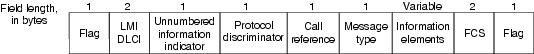
The previous section described the basic Frame Relay protocol format for carrying user data frames. The consortium Frame Relay specification also includes the LMI procedures. LMI messages are sent in frames distinguished by an LMI-specific DLCI (defined in the consortium specification as DLCI = 1023). The LMI message format is shown in Figure 18-3.
Figure 18-3 The LMI Message Format
In LMI messages, the basic protocol header is the same as in normal data frames. The actual LMI message begins with 4 mandatory bytes, followed by a variable number of information elements (IEs). The format and encoding of LMI messages is based on the ANSI T1S1 standard.
The first of the mandatory bytes (the unnumbered information indicator) has the same format as the Link Access Procedure, Balanced (LAPB) unnumbered information (UI) frame indicator with the poll/final bit set to 0. (For more information about LAPB, see Chapter 19.) The next byte is referred to as the protocol discriminator, which is set to a value that indicates LMI. The third mandatory byte (the call reference) is always filled with zeros.
The final mandatory byte is the Message Type field. Two message types have been defined. Status-enquiry messages allow the user device to inquire about network status. Status messages respond to status-enquiry messages. Keepalives (messages sent through a connection to ensure that both sides will continue to regard the connection as active) and PVC status messages are examples of these messages and are the common LMI features that are expected to be a part of every implementation that conforms to the consortium specification.
Together, status and status-enquiry messages help verify the integrity of logical and physical links. This information is critical in a routing environment because routing algorithms make decisions based on link integrity.
Following the Message Type field is some number of IEs. Each IE consists of a single-byte IE identifier, an IE Length field, and 1 or more bytes containing actual data.
Global Addressing
In addition to the common LMI features, several optional LMI extensions are extremely useful in an internetworking environment. The first important optional LMI extension is global addressing. As noted previously, the basic (nonextended) Frame Relay specification supports only values of the DLCI field that identify PVCs with local significance. In this case, no addresses identify network interfaces or nodes attached to these interfaces. Because these addresses do not exist, they cannot be discovered by traditional address resolution and discovery techniques. This means that with normal Frame Relay addressing, static maps must be created to tell routers which DLCIs to use to find a remote device and its associated internetwork address.
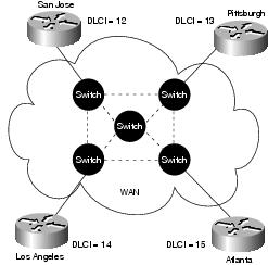
The global addressing extension permits node identifiers. With this extension, the values inserted in the DLCI field of a frame are globally significant addresses of individual end-user devices (for example, routers). This is implemented as shown in Figure 18-4.
Figure 18-4 Global Addressing Exchange
In Figure 18-4, note that each interface has its own identifier. Suppose that Pittsburgh must send a frame to San Jose. The identifier for San Jose is 12, so Pittsburgh places the value 12 in the DLCI field and sends the frame into the Frame Relay network. At the exit point, the DLCI field contents are changed by the network to 13 to reflect the source node of the frame. Each router interface has a distinct value as its node identifier, so individual devices can be distinguished. This permits adaptive routing in complex environments.
Global addressing provides significant benefits in a large, complex internetwork. The Frame Relay network now appears to the routers on its periphery like any LAN. No changes to higher-layer protocols are needed to take full advantage of their capabilities.
Multicasting
Multicasting is another valuable optional LMI feature. Multicast groups are designated by a series of four reserved DLCI values (1019 to 1022). Frames sent by a device using one of these reserved DLCIs are replicated by the network and sent to all exit points in the designated set. The multicasting extension also defines LMI messages that notify user devices of the addition, deletion, and presence of multicast groups.
In networks that take advantage of dynamic routing, routing information must be exchanged among many routers. Routing messages can be sent efficiently by using frames with a multicast DLCI. This allows messages to be sent to specific groups of routers.
Frame Relay Configuration
When implementing Frame Relay—and, specifically, LMI—in an internetwork, the LMI type must be consistent across all points between the end devices. The three LMI types that can be used are ANSI, Cisco, and Q.933A. The current Internetworking Operating System (IOS) on Cisco routers autosenses the LMI type from the frame switch to which it is attached.
Another important setting to consider when looking at Frame Relay networks is the initial encapsulation type used when the protocol is activated on an interface. This setting must be consistent between end devices on the internetwork. If you are connecting Cisco-only devices, Cisco encapsulation may be used. This is the default encapsulation type on Cisco routers. If you are connecting to hardware from other vendors, IETF encapsulation should be used.
Network Implementation
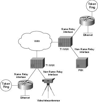
Frame Relay can be used as an interface to either a publicly available carrier-provided service or to a network of privately owned equipment. A typical means of private network implementation is to equip traditional T1 multiplexers with Frame Relay interfaces for data devices, as well as non-Frame Relay interfaces for other applications such as voice and video/teleconferencing. Figure 18-5 shows this configuration.
Figure 18-5 A Hybrid Frame Relay Network
A public Frame Relay service is deployed by putting Frame Relay switching equipment in the central offices of a telecommunications carrier. In this case, users can realize economic benefits from traffic-sensitive charging rates and are relieved from the work necessary to administer and maintain the network equipment and service.
In either type of network, the lines that connect user devices to the network equipment can operate at a speed selected from a broad range of data rates. Speeds between 56 kbps and 2 Mbps are typical, although Frame Relay can support lower and higher speeds.
Whether in a public or private network, the support of Frame Relay interfaces to user devices does not necessarily dictate that the Frame Relay protocol is used between the network devices. No standards for interconnecting equipment inside a Frame Relay network currently exist. Thus, traditional circuit-switching, packet-switching, or a hybrid approach combining these technologies can be used.
Troubleshooting Frame Relay
This section discusses troubleshooting procedures for connectivity problems related to Frame Relay links. It describes specific Frame Relay symptoms, the problems that are likely to cause each symptom, and the solutions to those problems.
The following sections cover the most common network issues in Frame Relay networks:
•
•
•
Frame Relay: Frame Relay Link Is Down
Symptom: Connections over a Frame Relay link fail. The output of the show interfaces serial exec command shows that the interface and line protocol are down, or that the interface is up and the line protocol is down.
Table 18-1 outlines the problems that might cause this symptom and describes solutions to those problems.
Table 18-1 Frame Relay: Frame Relay Link Is Down
A cabling, hardware, or carrier problem has occurred.
Perform these steps for the local and remote router:
1.
2.
3.
4.
For detailed information on troubleshooting serial lines, refer to Chapter 15, "Troubleshooting Serial Lines."
An LMI3 type mismatch has occurred.
1.
2.
3.
Keepalives are not being sent.
1.
2.
Encapsulation mismatch has occurred.
1.
2.
For information on viewing or changing the configuration of the non-Cisco device, refer to the vendor documentation.
The DLCI5 is inactive or has been deleted.
1.
2.
The DLCI is assigned to the wrong subinterface.
1.
Syntax:
frame-relay map protocol protocol-address dlci [broadcast] [ietf | cisco]
Syntax description:
•
•
•
•
•
•
Example:
The following example maps IP address 131.108.123.1 to DLCI 100:
interface serial 0
frame-relay map ip 131.108.123.1 100 broadcast
2.
1 DTE = data terminal equipment
2 DCE = data circuit-terminating equipment
3 LMI = Local Management Interface
4 IETF = Internet Engineering Task Force
5 DLCI = Data link connection identifier
6 PVC = permanent virtual circuit
Frame Relay: Cannot ping Remote Router
Symptom: Attempts to ping the remote router across a Frame Relay connection fail.
Table 18-2 outlines the problems that might cause this symptom and describes solutions to those problems.
Table 18-2 Frame Relay: Cannot ping Remote Router
Encapsulation mismatch has occurred.
1.
2.
For information on viewing or changing the configuration of the non-Cisco device, refer to the vendor documentation.
DLCI is inactive or has been deleted.
1.
2.
DLCI is assigned to the wrong subinterface.
1.
2.
An access list was misconfigured.
1.
2.
3.
4.
5.
The frame-relay map command is missing.
1.
2.
3.
Syntax:
•
Syntax Description:
•
•
•
•
•
•
Example:
The following example maps IP address 131.108.123.1 to DLCI 100:
interface serial 0
frame-relay map ip 131.108.123.1 100 broadcast
4.
For complete information on configuring Frame Relay address maps, refer to the Cisco IOS Wide-Area Networking Configuration Guide.
No broadcast keyword is found in frame-relay map statements.
1.
2.
Syntax:
frame-relay map protocol protocol-address dlci [broadcast] [ietf | cisco]
Syntax Description:
•
•
•
•
•
•
Example:
The following example maps IP address 131.108.123.1 to DLCI 100:
interface serial 0
frame-relay map ip 131.108.123.1 100 broadcast
Note: By default, the broadcast keyword is added to dynamic maps learned via Inverse ARP1 .
1 ARP = Address Resolution Protocol
Frame Relay: Cannot ping End to End
Symptom: Attempts to ping devices on a remote network across a Frame Relay connection fail.
Table 18-3 outlines the problems that might cause this symptom and describes solutions to those problems.