Downloads |
 Feedback Feedback
|
Table Of Contents
VINES: Clients Cannot Communicate with Servers over Router
VINES: Client Cannot Connect to Server over PSN
VINES: Client on Serverless Network Cannot Connect to Server over PSN
13
Troubleshooting Banyan VINES
Banyan Virtual Integrated Network Service (VINES) implements a distributed network operating system based on a proprietary protocol family derived from Xerox Corporation's Xerox Network Systems (XNS) protocols (see Chapter 14, "Troubleshooting XNS"). VINES uses a client/server architecture in which clients request certain services, such as file and printer access, from servers. Along with Novell's NetWare, IBM's LAN Server, and Microsoft's LAN Manager, VINES is one of the best-known distributed system environments for microcomputer-based networks.
VINES Technology Basics
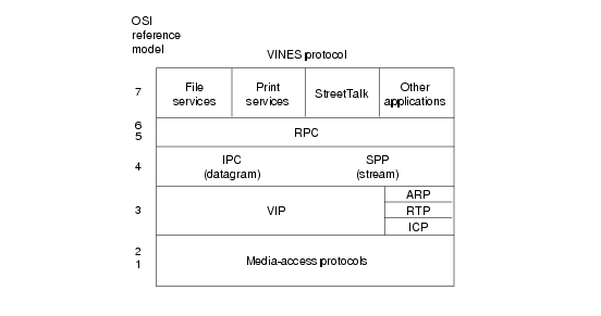
The VINES protocol stack is shown in Figure 13-1.
Figure 13-1 The VINES Protocol Stack
VINES Media Access
The two lower layers of the VINES stack are implemented with a variety of well-known media-access mechanisms, including High-Level Data Link Control (HDLC), Synchronous Data Link Control (SDLC) and derivatives, X.25, Ethernet, and Token Ring.
The Network Layer
VINES uses the VINES Internetwork Protocol (VIP) to perform Layer 3 activities (including internetwork routing). VINES also supports its own Address Resolution Protocol (ARP), its own version of the Routing Information Protocol (RIP) called the Routing Table Protocol (RTP), and the Internet Control Protocol (ICP), which provides exception handling and special routing cost information. ARP, ICP, and RTP packets are encapsulated in a VIP header.
VIP
VINES network-layer addresses are 48-bit entities subdivided into network (32 bits) and subnetwork (16 bits) portions. The network number is better described as a server number because it is derived directly from the server's key (a hardware module that identifies a unique number and the software options for that server). The subnetwork portion of a VINES address is better described as a host number because it is used to identify hosts on VINES networks. Figure 13-2 illustrates the VINES address format.
Figure 13-2 The VINES Address Format
The network number identifies a VINES logical network, which is represented as a two-level tree with the root at a service node. Service nodes, which are usually servers, provide address resolution and routing services to clients, which represent the leaves of the tree. The service node assigns VIP addresses to clients.
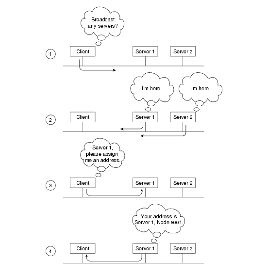
When a client is powered on, it broadcasts a request for servers. All servers that hear the request respond. The client chooses the first response and requests a subnetwork (host) address from that server. The server responds with an address consisting of its own network address (derived from its key), concatenated with a subnetwork (host) address of its own choosing. Client subnetwork addresses are typically assigned sequentially, starting with 8001H. Server subnetwork addresses are always 1. The VINES address selection process is shown in Figure 13-3.
Figure 13-3 The VINES Address Selection Process
Dynamic address assignment is not unique in the industry (AppleTalk also uses this process), but it is certainly not as common as static address assignment. Because addresses are chosen exclusively by a particular server (whose address is unique as a result of the uniqueness of the hardware key), there is very little chance of a duplicate address (a potentially devastating problem on Internet Protocol [IP] and other networks).
In the VINES network scheme, all servers with multiple interfaces are essentially routers. A client always chooses its own server as a first-hop router, even if another server on the same cable provides a better route to the ultimate destination. A client can learn about other routers by receiving redirect messages from its own server. Because clients rely on their servers for first-hop routing, VINES servers maintain routing tables to help them find remote nodes.
VINES routing tables consist of host/cost pairs, where host corresponds to a network node that can be reached and cost corresponds to a delay, expressed in milliseconds, to get to that node. RTP helps VINES servers find neighboring clients, servers, and routers.
Periodically, all clients advertise both their network-layer and their Media Access Control (MAC)-layer addresses with the equivalent of a hello packet. Hello packets indicate that the client is still operating and network ready. The servers themselves send routing updates to other servers periodically. Routing updates alert other routers to changes in node addresses and network topology.
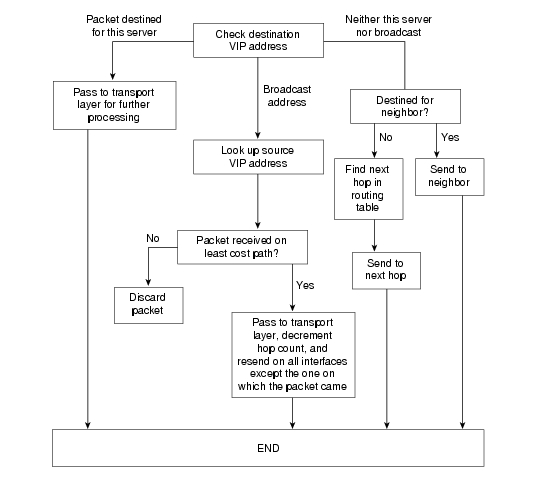
When a VINES server receives a packet, it checks whether the packet is destined for another server or if it's a broadcast. If the current server is the destination, the server handles the request appropriately. If another server is the destination, the current server either forwards the packet directly (if the server is a neighbor) or routes it to the next server in line. If the packet is a broadcast, the current server checks whether the packet came from the least-cost path. If it did not, the packet is discarded. If it did, the packet is forwarded on all interfaces except the one on which it was received. This approach helps diminish the number of broadcast storms, a common problem in other network environments. The VINES routing algorithm is shown in Figure 13-4.
Figure 13-4 The VINES Routing Algorithm
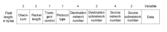
The VIP packet format is shown in Figure 13-5.
Figure 13-5 The VIP Packet Format
The fields of a VIP packet are as follows:
•
Checksum—Used to detect packet corruption.
•
•
•
•
RTP
RTP distributes network topology information. Routing update packets are broadcast periodically by both client and service nodes. These packets inform neighbors of a node's existence and indicate whether the node is a client or a service node. Service nodes also include, in each routing update packet, a list of all known networks and the cost factors associated with reaching those networks.
Two routing tables are maintained: a table of all known networks and a table of neighbors. For service nodes, the table of all known networks contains an entry for each known network except the service node's own network. Each entry contains a network number, a routing metric, and a pointer to the entry for the next hop to the network in the table of neighbors. The table of neighbors contains an entry for each neighbor service node and client node. Entries include a network number, a subnetwork number, the media-access protocol (for example, Ethernet) used to reach that node, a local-area network (LAN) address (if the medium connecting the neighbor is a LAN), and a neighbor metric.
RTP specifies four packet types:
•
•
•
•
Each RTP packet has a 4-byte header consisting of the following 1-byte fields:
•
•
•
•
Both the controller type and the machine type fields are used for pacing.
ARP
ARP entities are classified as either address resolution clients or address resolution services. Address resolution clients are usually implemented in client nodes, whereas address resolution services are typically provided by service nodes.
An ARP packet has an 8-byte header consisting of a 2-byte packet type, a 4-byte network number, and a 2-byte subnetwork number. There are four packet types: a query request, which is a request for an ARP service; a service response, which is a response to a query request; an assignment request, which is sent to an ARP service to request a VINES internetwork address; and an assignment response, which is sent by the ARP service as a response to the assignment request. The network number and subnet number fields have meaning only in an assignment response packet.
ARP clients and services implement the following algorithm when a client starts up. First, the client broadcasts query request packets. Then, each service that is a neighbor of the client responds with a service response packet. The client then issues an assignment request packet to the first service that responded to its query request packet. The service responds with an assignment response packet containing the assigned internetwork address.
ICP
ICP defines exception notification and metric notification packets. Exception notification packets provide information about network-layer exceptions; metric notification packets contain information about the final transmission used to reach a client node.
Exception notifications are sent when a VIP packet cannot be routed properly, and the error subfield in the VIP header's transport control field is enabled. These packets also contain a field identifying the particular exception by its error code.
ICP entities in service nodes generate metric notification messages when the metric subfield in the VIP header's transport control field is enabled, and the destination address in the service node's packet specifies one of the service node's neighbors.
The Transport Layer
VINES provides three transport-layer services:
•
•
•
Upper-Layer Protocols
As a distributed network, VINES uses the remote-procedure call (RPC) model for communication between clients and servers. RPC is the foundation of distributed service environments. The NetRPC protocol (Layers 5 and 6) provides a high-level programming language that allows access to remote services in a manner transparent to both the user and the application.
At Layer 7, VINES offers file-service and print-service applications, as well as StreetTalk, which provides a globally consistent name service for an entire internetwork.
VINES also provides an integrated applications development environment under several operating systems, including DOS and UNIX. This development environment allows third parties to develop both clients and services that run in the VINES environment.
Troubleshooting Banyan VINES
This section presents protocol-related troubleshooting information for connectivity problems related to Banyan VINES. It describes specific VINES symptoms, the problems that are likely to cause each symptom, and the solutions to those problems.
The following sections describe the most common errors experienced in Banyan VINES networks:
•
•
•
VINES: Clients Cannot Communicate with Servers over Router
Symptom: Clients cannot connect to VINES servers over one or more routers. Clients might or might not be able to connect to servers on their directly connected networks.
Table 13-1 outlines the problems that might cause this symptom and describes solutions to those problems.
Table 13-1 VINES: Clients Cannot Communicate with Servers over Router
Router interface is down
1.
2.
Refer to the troubleshooting chapter that covers the media type used in your network.
Hardware or media problem
For information on troubleshooting hardware problems, refer to the troubleshooting chapter that covers the media type used in your network.
Addressing problem
1.
2.
vines routing [address | recompute]
Addressing problem (continued)
Syntax Description:
•
•
VINES metric value is not specified
1.
2.
Configure the vines metric based on whether the interface is LAN or WAN connected. Suggested metrics for LAN and WAN connections follow:
•
•
•
•
Missing vines serverless or vines arp-enable commands
A network that does not have an attached server must be configured with the vines serverless broadcast and vines arp-enable router configuration commands.
Note: These commands are enabled by default in Cisco IOS Release 10.3 and later.
1.
2.
Missing vines serverless or vines arp-enable commands (continued)
Syntax:
The following syntax is required to enable vines serverless:
vines serverless [dynamic | broadcast]
Syntax Description:
•
•
Syntax:
The following syntax is required to enable vines arp-enable:
vines arp-enable [dynamic]
Syntax Description:
•
Misconfigured access list
1.
2.
3.
4.
Misconfigured access list (continued)
5.
6.
1 FDDI = Fiber Distributed Data Interface
2 ARP = Address Resolution Protocol
3 SARP = Sequence Address Resolution Protocol
VINES: Client Cannot Connect to Server over PSN
Symptom: Clients cannot connect to VINES servers across a packet-switched network (PSN). Clients can connect to local VINES servers.
Table 13-2 outlines the problems that might cause this symptom and describes solutions to those problems.
Table 13-2 VINES: Client Cannot Connect to Server over PSN
Address mapping error
1.
2.
3.
PVC2 is not set up
1.
2.
1 DLCI = Data Link Connection Identifier
2 PVC = permanent virtual circuit
VINES: Client on Serverless Network Cannot Connect to Server over PSN
Symptom: Clients on a serverless network (that is, a network segment that has no attached VINES servers) cannot open a connection to a VINES server over a PSN.
Table 13-3 outlines the problems that might cause this symptom and describes solutions to those problems.
Table 13-3 VINES: Client on Serverless Network Cannot Connect to Server over PSN
Address mapping error
1.
2.
Syntax:
x25 map protocol address [protocol2 address2[...[protocol9 address9]]] x121-address [option]
no x25 map protocol address x121-addressAddress mapping error (continued)
Syntax:
•
•
•
•
3.
Syntax:
frame-relay map protocol protocol-address dlci [broadcast] [ietf | cisco]
[payload-compress {packet-by-packet | frf9 stac [hardware-options]}]
no frame-relay map protocol protocol-addressSyntax Description:
•
•
•
•
•
Address mapping error (continued)
•
•
•
PVC4 is not set up
1.
2.
VINES broadcasts are not forwarded across the PSN
1.
2.
VINES broadcasts not forwarded to all router interfaces
1.
2.
Note: The vines serverless broadcast command is enabled by default in Cisco IOS Release 10.3 and later.
1 DLCI = Data Link Connection Identifier
2 IETF = Internet Engineering Task Force
3 CSA = compression service adapter
4 PVC = permanent virtual circuit