[an error occurred while processing this directive]

Support

Troubleshooting DECnet

Hierarchical Navigation

 Feedback

Table Of Contents

Troubleshooting DECnet

Digital Network Architecture

The Network Layer

DECnet Phase IV Routing Frame Format

Addressing

Routing Levels

The Transport Layer

Upper-Layer Protocols

Troubleshooting DECnet

Using DECnet in a Multiprotocol Environment

DECnet: Connections to DEC Hosts Fail over Router (End Node Problem)

Configuring a DECnet Node to Log DECnet Events

DECnet: Connections to DEC Hosts Fail over Router  (Router Problem)

DECnet: End Nodes Cannot Find Designated Router

DECnet: Router or End Node Sees Incorrect Designated Router

DECnet: Routers Not Establishing Adjacencies

DECnet: Routing Node Adjacencies Toggle Up and Down

DECnet: No Phase IV Connectivity over Phase V Backbone

DECnet Phase IV and ISO CLNS Addresses

DECnet: Poor Performance


Troubleshooting DECnet


Digital Equipment Corporation (Digital) developed the DECnet protocol family to provide a well-thought-out way for its computers to communicate with one another. The first version of DECnet, released in 1975, allowed two directly attached PDP-11 minicomputers to communicate. In more recent years, Digital has included support for nonproprietary protocols, but DECnet remains the most important of Digital's network product offerings.

DECnet is currently in its fifth major product release (sometimes called Phase V and referred to as DECnet/OSI in Digital literature). DECnet Phase V is a superset of the OSI protocol suite and supports all OSI protocols as well as several other proprietary and standard protocols that were supported in previous versions of DECnet. As with past changes to the protocol, DECnet Phase V is compatible with the previous release (Phase IV, in this case).

Digital Network Architecture

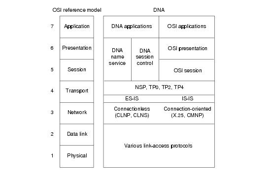
Contrary to popular belief, DECnet is not a network architecture at all but is, rather, a series of products conforming to Digital's Digital Network Architecture (DNA). Like most comprehensive network architectures from large systems vendors, DNA supports a large set of both proprietary and standard protocols. The list of DNA-supported technologies grows constantly as Digital implements new protocols. Figure 11-1 illustrates an incomplete snapshot of DNA and the relationship of some of its components to the OSI reference model.

Figure 11-1 DNA and the OSI Reference Model

As Figure 11-1 shows, DNA supports a variety of media and link implementations. Among these are well-known standards such as Ethernet, Token Ring, Fiber Distributed Data Interface (FDDI), IEEE 802.2, and X.25. DNA also offers a traditional point-to-point link-layer protocol called Digital Data Communications Message Protocol (DDCMP) and a 70-Mbps bus used in the VAX cluster called the computer-room interconnect bus (CI bus).

The Network Layer

DECnet supports both connectionless and connection-oriented network layers. Both network layers are implemented by OSI protocols. The connectionless implementation uses the Connectionless Network Protocol (CLNP) and the Connectionless Network Service (CLNS). The connection-oriented network layer uses the X.25 Packet-Level Protocol (PLP), which is also known as X.25 Level 3, and the Connection-Mode Network Protocol (CMNP).

Although most of DNA was brought into OSI conformance with DECnet Phase V, DECnet Phase IV routing was already very similar to OSI routing. Phase V DNA routing consists of OSI routing (ES-IS and IS-IS), plus continued support for the DECnet Phase IV routing protocol.

DECnet Phase IV Routing Frame Format

The DECnet Phase IV routing protocol differs from IS-IS in several ways. One difference is in the protocol header. The DNA Phase IV routing layer header is shown in Figure 11-2; IS-IS packet formats are shown in Chapter 12, "Troubleshooting ISO CLNS."

Figure 11-2 A DNA Phase IV Routing Layer Header

The first field in a DNA Phase IV routing header is the routing flags field, which includes:

A return-to-sender bit that, if set, indicates that the packet is returning to the source.

A return-to-sender-request bit that, if set, indicates that request packets should be returned to the source if they cannot be delivered to the destination.

An intraLAN bit, which is on by default. If the router detects that the two communicating end systems are not on the same subnetwork, it turns the bit off.

Other bits that indicate header format, whether padding is being used, and other functions.

The destination node and source node fields identify the network addresses of the destination nodes and the source node.

The nodes traversed field shows the number of nodes the packet has traversed on its way to the destination. This field allows implementation of a maximum hop count so that obsolete packets can be removed from the network.

DECnet identifies two types of nodes: end nodes and routing nodes. Both end nodes and routing nodes can send and receive network information, but only routing nodes can provide routing services for other DECnet nodes.

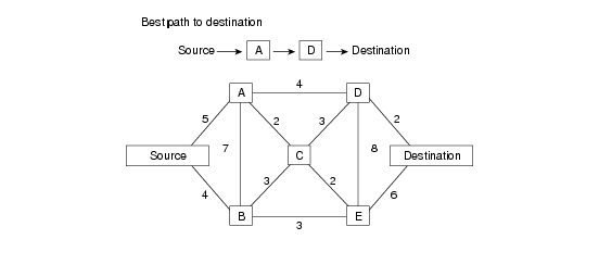
DECnet routing decisions are based on cost, an arbitrary measure assigned by network administrators to be used in comparing various paths through an internetwork environment. Costs are typically based on hop count, media bandwidth, or other measures. The lower the cost, the better the path. When network faults occur, the DECnet Phase IV routing protocol uses cost values to recalculate the best paths to each destination. Figure 11-3 illustrates the calculation of costs in a DECnet Phase IV routing environment.

Figure 11-3 A DECnet Phase IV Routing Protocol Cost Calculation

Addressing

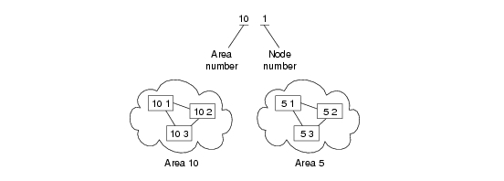
DECnet addresses are not associated with the physical networks to which the nodes are connected. Instead, DECnet locates hosts using area/node address pairs. An area's value ranges from 1 to 63, inclusive. A node address can be between 1 and 1023, inclusive. Therefore, each area can have 1023 nodes, and approximately 65,000 nodes can be addressed in a DECnet network. Areas can span many routers, and a single cable can support many areas. Therefore, if a node has several network interfaces, it uses the same area/node address for each interface. Figure 11-4 shows a sample DECnet network with several addressable entities.

Figure 11-4 Examples of DECnet Addresses

DECnet hosts do not use manufacturer-assigned Media Access Control (MAC)-layer addresses. Instead, network-level addresses are embedded in the MAC-layer address according to an algorithm that multiplies the area number by 1,024 and adds the node number to the product. The resulting 16-bit decimal address is converted to a hexadecimal number and appended to the address AA00.0400 in byte-swapped order, with the least significant byte first. For example, DECnet address 12.75 becomes 12363 (base 10), which equals 304B (base 16). After this byte-swapped address is appended to the standard DECnet MAC address prefix, the resulting address is AA00.0400.4B30.

Routing Levels

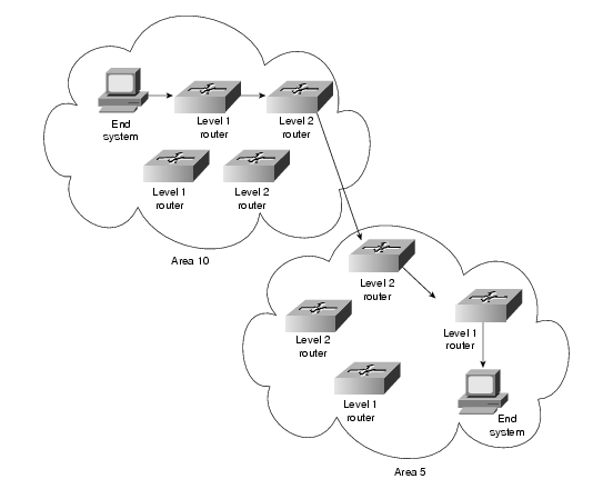
DECnet routing nodes are referred to as either Level 1 or Level 2 routers. A Level 1 router communicates with end nodes and with other Level 1 routers in a particular area. Level 2 routers communicate with Level 1 routers in the same area and with Level 2 routers in different areas. Together, Level 1 and Level 2 routers form a hierarchical routing scheme. This relationship is illustrated in Figure 11-5.

Figure 11-5 DECnet Level 1 and Level 2 Routers

End systems send routing requests to a designated Level 1 router. The Level 1 router with the highest priority is elected to be the designated router. If two routers have the same priority, the one with the larger node number becomes the designated router. A router's priority can be manually configured to force it to become the designated router.

As shown in Figure 11-5, multiple Level 2 routers can exist in any area. When a Level 1 router wishes to send a packet outside its area, it forwards the packet to a Level 2 router in the same area. In some cases, the Level 2 router may not have the optimal path to the destination, but the mesh network configuration offers a degree of fault tolerance not provided by the simple assignment of one Level 2 router per area.

The Transport Layer

The DNA transport layer is implemented by a variety of transports, both proprietary and standard. OSI transports TP0, TP2, and TP4 are supported.

Digital's own Network Services Protocol (NSP) is functionally similar to TP4 in that it offers connection-oriented, flow-controlled service with message fragmentation and reassembly. Two subchannels are supported—one for normal data and one for expedited data and flow control information. Two flow control types are supported—a simple start/stop mechanism where the receiver tells the sender when to terminate and resume data transmission and a more complex flow control technique, where the receiver tells the sender how many messages it can accept. NSP can also respond to congestion notifications from the network layer by reducing the number of outstanding messages it will tolerate.

Upper-Layer Protocols

Above the transport layer, DECnet supports its own proprietary upper-layer protocols as well as standard OSI upper-layer protocols. DECnet application protocols use the DNA session control protocol and the DNA name service. OSI application protocols are supported by OSI presentation- and session-layer implementations.

Troubleshooting DECnet

This section presents protocol-related troubleshooting information for DECnet Phase IV connectivity and performance problems. The procedures outlined apply only to environments in which DECnet routing is enabled on the router, not to environments in which DECnet is being bridged (that is, bridging is enabled on the router interfaces and EtherType 6003 is being passed).

This chapter does not discuss other Digital protocols, such as Maintenance Operation Protocol (MOP), local-area transport (LAT), local-area VAX cluster (LAVC), and local-area systems technology (LAST).


Note For information about troubleshooting ISO CLNS (DECnet Phase V) problems, refer to Chapter 12, "Troubleshooting ISO CLNS."


The section "Using DECnet in a Multiprotocol Environment" discusses possible problems when using DECnet in an internetwork running other protocols as well. The remaining sections describe specific DECnet symptoms, the problems that are likely to cause each symptom, and the solutions to those problems.

The following sections outline the most common network issues in DECnet networks:

DECnet: Connections to DEC Hosts Fail over Router (End Node Problem)

DECnet: Connections to DEC Hosts Fail over Router  (Router Problem)

DECnet: End Nodes Cannot Find Designated Router

DECnet: Router or End Node Sees Incorrect Designated Router

DECnet: Routers Not Establishing Adjacencies

DECnet: Routing Node Adjacencies Toggle Up and Down

DECnet: No Phase IV Connectivity over Phase V Backbone

DECnet: Poor Performance


Note In some of the symptom discussions that follow, Operator Communication Manager (OPCOM) messages are used to illustrate certain errors. These examples assume that OPCOM is running and event logging is enabled. For more information about event logging, see the section "Configuring a DECnet Node to Log DECnet Events" later in this chapter.


Using DECnet in a Multiprotocol Environment

It is important to remember that DECnet changes the MAC addresses of router interfaces. This behavior can cause problems for other protocols that are already enabled on the router.

If after enabling DECnet on a router interface other protocols (such as Novell IPX or XNS) experience connectivity loss due to address resolution problems, the problem is probably a result of DECnet changing the MAC address of the router interface.

As a rule, enable DECnet on router interfaces first, and then enable other protocols. Otherwise, use the copy running-config startup-config command to save the router configuration and then reload the router.

DECnet: Connections to DEC Hosts Fail over Router (End Node Problem)

Symptom: DECnet nodes cannot communicate when attempting to make connections over routers.


Note This section focuses on problems in end nodes. For router-related problems and solutions, see the section "DECnet: Connections to DEC Hosts Fail over Router  (Router Problem)" later in this chapter.


Table 11-1 outlines the problems that might cause this symptom and describes solutions to those problems.

Table 11-1 DECnet: Connections to DEC Hosts Fail over Router (End Node Problem) 

Possible Problem
Solution

Misconfigured end node

1. Check the end node configuration using the show executor characteristics NCP1 command.

2. Make sure that the end node type (nonrouting Phase IV, routing Phase IV, area), node address, node name, and routing and link parameters are correctly specified.

3. Check the circuit characteristics using the show known circuit characteristics NCP command.

4. Make sure that the designated router, hello timer, router priority (if the node is a routing node), and other circuit characteristics are properly configured.

The following decnet commands are used to set the designated router, hello timers, and router priority on a Cisco router:

decnet hello-timer seconds

seconds—Interval at which the Cisco IOS software sends hello messages. It can be a decimal number in the range 1 to 8191 seconds. The default is 15 seconds.

decnet router-priority value

To elect a designated router to which packets will be sent when no destination is specified, use the decnet router-priority interface configuration command.

value—Priority of the router. This can be a number in the range 0 through 127. The larger the number, the higher the priority. The default priority is 64.

Misconfigured end node (continued)

5. Reconfigure the end node if any of the end node or circuit characteristics are misconfigured. For information on configuring end nodes, refer to the vendor documentation.

Host access control rejects connection

With this problem, users see the message "connect failed, access control rejected." This is typically a session-layer problem.

1. Make sure that the following requirements are satisfied:

User-supplied access control information is correct

Proxy access is set up correctly

Proxy database and proxy account are correct

2. Make sure that the user's security access matches the access specifications for the user on the remote systems.

3. If there are problems in any of these areas, make changes as necessary.

Unrecognized object

With this problem, users see the message "connect failed, unrecognized object."

1. Use the tell NCP command to determine whether the object is defined on the target node. The syntax of the tell command is as follows:

tell target-node-name show known objects

2. If the object is not defined, log in as superuser and run NCP to define the object with the set object NCP command, as follows:

set object object-id

3. After the object is defined, use the tell NCP command to determine whether the object has a file specified, as follows:

tell target-node-name show object object-id character

4. Exit NCP and determine whether the file specified for the object exists.

5. If the file for the requested object does not exist, create the file.

6. Make sure the permissions for the specified file are correct.

Insufficient resource error

With an insufficient resource error, VMS2 users see the following message:

% system-E-REMRSC, insufficient system resource at remote node

Note: This error message might not indicate a problem. These parameter values can be set intentionally to prevent network connections beyond a certain number.

Try tuning the following DEC target system parameters:

SYSGEN parameters:

MAXPROCESSCNT

NCP parameters:

MAXIMUM LINKS

ALIAS MAXIMUM LINKS

AUTHORIZE parameters:

MAXJOBS

MAXACCTJOBS

1 NCP = Network Control Program

2 VMS = Virtual Memory System


Configuring a DECnet Node to Log DECnet Events

In addition to the diagnostic tools available on your router, DECnet environments provide a wealth of diagnostic information. DECnet nodes can use the DECnet Event Logging Facility (EVL) to track DECnet events. EVL allows you to monitor significant network events, such as lost packets and circuit failures.

The following steps outline the basic tasks required to enable event logging on a VMS system:


Step 1 Determine whether the OPCOM process is running:

$ show system

Step 2 If OPCOM does not appear in the list of running processes, enter the following command to start it:

$ @sys$system:STARTUP.com OPCOM

Step 3 Use the NCP to enable event logging:

$ MCR NCP
NCP> SET logging MONITOR KNOWN Events
NCP> DEFINE logging MONITOR KNOWN Events
NCP> SET logging MONITOR STATE ON
NCP> DEFINE logging MONITOR STATE ON

Step 4 Exit NCP:

NCP> Exit

Step 5 To monitor network events from a console terminal, enter the following command at the VMS system prompt:

$ REPLY/ENABLE = NETWORK

(This command is equivalent to the terminal monitor privileged exec command.)

DECnet: Connections to DEC Hosts Fail over Router  (Router Problem)

Symptom: DECnet nodes cannot communicate when attempting to make connections over routers.


Note This section focuses on problems in the router. For end node-related problems and solutions, see the section "DECnet: Connections to DEC Hosts Fail over Router (End Node Problem)" earlier in this chapter.


Table 11-2 outlines the problems that might cause this symptom and describes solutions to those problems.

Table 11-2 DECnet: Connections to DEC Hosts Fail over Router (Router Problem) 

Possible Problem
Solution

DECnet is not enabled on router

1. Use the show decnet interface privileged exec command to see on which interfaces, if any, DECnet is enabled.

2. If the output shows that DECnet is not enabled, use the show running-config privileged exec command to view the router configuration. Determine whether DECnet global and interface command specifications are configured on the router.

3. Enable DECnet routing on the appropriate routers and interfaces. For detailed information on configuring DECnet, refer to the Cisco IOS Network Protocols Configuration Guide, Part 2.

Missing decnet cost command

1. Make sure that there is a cost configured on DECnet interfaces. Check the configuration for a decnet cost cost-value interface configuration command entry.

2. If the command is not present, add the decnet cost command for each interface on which DECnet is enabled.

End nodes and router area number mismatch

1. Check the configuration of end nodes and routers on the network segment. Check the area address specified on end nodes and routers.

2. If an end node is not in the same area as a router on the segment, you must either change the address of the end node to be the same as a router on the segment, or you must reconfigure a router on the segment with the same area number as the end node.

Actual cost to the destination area is more than the configured cost

1. Use the show decnet interface exec command to determine the configured maximum cost to the destination area.

2. Use the show decnet route exec command to determine the actual cost to the destination area.

3. If the actual cost is more than the configured maximum cost, increase the maximum cost configured on the router.

On Level 1 routers, use the decnet max-cost global configuration command to increase the area maximum cost.

On Level 2 routers, use the decnet area-max-cost global configuration command to increase the area maximum cost.

Actual number of hops to the desti- nation is more than the configured maximum number of hops

1. Use the show decnet interface command to determine the maximum number of hops allowed for intra-area routing.

2. Use the show decnet route exec command to determine the actual number of hops to the destination as shown in the DECnet routing table.

3. If the actual number of hops is more than the configured maximum allowed hops, increase the maximum hops configured on the router.

On Level 1 routers, use the decnet max-hops global configuration command to increase the maximum hops.

On Level 2 routers, use the decnet area-max-hops global configuration command to increase the maximum number of hops.

Access list is misconfigured

1. Use the show decnet access-list privileged exec command to determine whether there are DECnet access lists configured on the router.

2. If there are access lists applied to router interfaces, use the debug decnet connects privileged exec command to determine whether important packets are being forwarded properly.

Caution: Because debugging output is assigned high priority in the CPU process, it can render the system unusable. For this reason, use debug commands only to troubleshoot specific problems or during troubleshooting sessions with Cisco technical support staff. Moreover, it is best to use debug commands during periods of lower network traffic and fewer users. Debugging during these periods decreases the likelihood that increased debug command processing overhead will affect system use.

3. If packets are being dropped, disable all access lists on the router using the no decnet access-group interface configuration command.

4. Determine whether connections to hosts are now possible. If connections are made successfully, a misconfigured access list is probably the problem.

5. Enable access lists on the router using the decnet access-group interface configuration command. Enable the lists one at a time until connectivity is lost, at which point you have found the problem access list.

6. Modify the access list as necessary. Make sure to include explicit permit statements for traffic that you want to be forwarded normally.

7. If problems persist, continue the process until you have isolated all problem access lists.

Node address out of range

1. Use the show running-config privileged exec command to view router configurations. Check to see whether the decnet max-address global configuration command has been configured. This command sets the highest DECnet node number allowed in the area.

Note: The decnet max-address command specifies the highest node number allowed in an area, not the maximum number of node addresses allowed in an area. For example, if you configure the command decnet max-address 1000 on a router and you configure a node with a node address of 1001, the address is out of range.

2. The default maximum address is 1023. However, if another value is configured, the node address might be more than the configured value. If this is the case, increase the maximum address value using the decnet max-address command.

Partitioned area

Make sure the network topology has no discontiguous areas. If any discontiguous areas exist, reconfigure the topology by changing area addresses or by creating a path (with a router) to create a contiguous network.

Media problem

For information on troubleshooting serial lines, refer to Chapter 15, "Troubleshooting Serial Lines." For information on troubleshooting LAN media, refer to the media troubleshooting chapter that covers the media type used in your network.


DECnet: End Nodes Cannot Find Designated Router

Symptom: End nodes cannot find a designated router. End nodes cannot access nodes that are on different LANs, but other nodes connected to the same LAN are accessible.

Table 11-3 outlines the problems that might cause this symptom and describes solutions to those problems.

Table 11-3 DECnet: End Nodes Cannot Find Designated Router 

Possible Problem
Solution

DECnet not enabled on router

1. Use the show running-config privileged exec command to view the router configuration. Determine whether DECnet global configuration and interface command specifications are configured on the router.

2. Enable DECnet routing on the appropriate routers and interfaces. For detailed information on configuring DECnet, refer to the Cisco IOS Network Protocols Configuration Guide, Part 2.

End nodes and router area number mismatch

1. Check the configuration of end nodes and routers on the network segment. Check the area address specified on end nodes and routers. Use the show running-config privileged exec command to view the router configuration.

2. If an end node is not in the same area as a router on the segment, you must either change the address of the end node to be the same as that of a router on the segment, or you must reconfigure a router on the segment with the same area number as the end node.

Hello packets are not being exchanged

1. Use the debug decnet adj privileged exec command to determine whether the router is sending hello packets and whether hellos are being received.

2. Caution: Because debugging output is assigned high priority in the CPU process, it can render the system unusable. For this reason, use debug commands only to troubleshoot specific problems or during troubleshooting sessions with Cisco technical support staff. Moreover, it is best to use debug commands during periods of lower network traffic and fewer users. Debugging during these periods decreases the likelihood that increased debug command processing overhead will affect system use.

3. If no exchange is occurring, use the show interfaces exec command to determine whether the interface input and output queues are full. A full input queue is indicated by a value of 75/75, and a full output queue is indicated by a value of 40/40.

4. If the queues are full and no hello packets are being exchanged, contact your technical support representative.

5. If routers are sending hello packets, check end nodes to determine why end nodes are rejecting hello packets.

Media problem

For information on troubleshooting serial lines, refer to Chapter 15, "Troubleshooting Serial Lines." For information on troubleshooting LAN media, refer to the media troubleshooting chapter that covers the media type used in your network.


DECnet: Router or End Node Sees Incorrect Designated Router

Symptom: Routers and end nodes see an incorrect or an unexpected designated router. If your network requires a specific router to be elected the designated router, allowing another router to become a designated router can cause unpredictable network behavior and can block connectivity in and out of the area.

Table 11-4 outlines the problems that might cause this symptom and describes solutions to those problems.

Table 11-4 DECnet: Router or End Node Sees Incorrect Designated Router 

Possible Problem
Solution

Priority of the expected designated router is not configured correctly

1. Use the show decnet interface exec command to determine which router is the designated router. Note the priority of the router that is shown in the command output.

2. If the designated router identified in the output is not the correct router, use the show decnet interface command on the expected designated router and the actual designated router.

3. Compare the priority of the actual designated router with that of the expected designated router. The router that you want to be the designated router should have the highest priority.

Syntax:

4. If necessary, use the decnet router-priority interface configuration command to give a higher priority to a router so that it will be elected the designated router.

The following is the syntax for the decnet router-priority command:

decnet router-priority value

To elect a designated router to which packets will be sent when no destination is specified, use the decnet router-priority interface configuration command.

Syntax:

value—Priority of the router. This can be a number in the range 0 through 127. The larger the number, the higher the priority. The default priority is 64.

Multiple routers have the same router priority

1. Use the show decnet interface command to determine which router is the designated router. Note the priority of the router that is shown in the command output.

2. Use the show decnet interface command on the expected designated router and compare the priorities of the actual and the expected designated routers.

3. If the routers have the same priority, use the decnet router-priority interface configuration command to configure a higher priority on the router that should be elected the designated router.

Multiple routers have the same router priority (continued)

Syntax:

The following is the syntax for the decnet router-priority command:

decnet router-priority value

To elect a designated router to which packets will be sent when no destination is specified, use the decnet router-priority interface configuration command.

Syntax:

value—Priority of the router. This can be a number in the range 0 through 127. The larger the number, the higher the priority. The default priority is 64.

Note: If two routers are configured with the same priority, the router with the higher node number will become the designated router.

Adjacency between nodes is not bidirectional

1. Use the show decnet route exec command to see whether the adjacency with the expected designated router is in a "down" or "initializing" state.

2. Use the debug decnet adj privileged exec command to determine whether hello packets are being exchanged.

Caution: Because debugging output is assigned high priority in the CPU process, it can render the system unusable. For this reason, use debug commands only to troubleshoot specific problems or during troubleshooting sessions with Cisco technical support staff. Moreover, it is best to use debug commands during periods of lower network traffic and fewer users. Debugging during these periods decreases the likelihood that increased debug command processing overhead will affect system use.

3. If a router is not sending hello packets, use the show interfaces command to determine whether the interface input and output queues are full. A full input queue is indicated by a value of 75/75, and a full output queue is indicated by a value of 40/40.

4. If the queues are full, and no hello packets are being exchanged, contact your router technical support representative.

5. If routers are sending hello packets, contact end-node administrators to determine why end nodes are rejecting hello packets.


DECnet: Routers Not Establishing Adjacencies

Symptom: Routers do not establish adjacencies with other routers on the same LAN.

Table 11-5 outlines the problems that might cause this symptom and describes solutions to those problems.

Table 11-5 DECnet: Routers Not Establishing Adjacencies 

Possible Problem
Solution

More than 32 routers on the network

DECnet limits the number of adjacencies that can be established by a router to 32.

1. Enable the debug decnet events privileged exec command to determine whether the adjacency is being rejected. Enable this command on one router at a time.

Caution: Because debugging output is assigned high priority in the CPU process, it can render the system unusable. For this reason, use debug commands only to troubleshoot specific problems or during troubleshooting sessions with Cisco technical support staff. Moreover, it is best to use debug commands during periods of lower network traffic and fewer users. Debugging during these periods decreases the likelihood that increased debug command processing overhead will affect system use.

2. If the adjacency is being rejected, reduce the number of adjacent routers or increase the priority of a router that you want to be adjacent so that it has a higher priority than one of the other neighboring routers. An adjacency will be established with the router you want instead of with a router assigned a lower priority.

Syntax:

The following is the syntax to adjust the priority of a router:

decnet router-priority value

To elect a designated router to which packets will be sent when no destination is specified, use the decnet router-priority interface configuration command.

Syntax Description:

value—Priority of the router. This can be a number in the range 0 through 127. The larger the number, the higher the priority. The default priority is 64.

Node address out of range

1. Use the show running-config privileged exec command to view router configurations. Check to see whether the decnet max-address global configuration command has been configured. This command sets the highest DECnet node number allowed in the area.

Note: The decnet max-address command specifies the highest node number allowed in an area, not the maximum number of node addresses allowed in an area. For example, if you configure the command decnet max-address 1000 on a router and you configure a node with a node address of 1001, the address is out of range.

2. The default maximum address is 1023. However, if another value is configured, the node address might be more than the configured value. If this is the case, increase the maximum address value using the decnet max-address command.

Router area number is higher than configured decnet max-area

If the area number of a DECnet node (such as a router) is higher than the configured decnet max-area value, the adjacency will be reset.

1. Use the show running-config privileged exec command to view the router configuration. Look for decnet max-area global configuration command entries. This command sets the DECnet maximum area number for the router.

Note: The decnet max-area command specifies the highest area value allowed in the network, not the maximum number of areas configurable. For example, if you configure the command decnet max-area 60 and you configure a node with area number 61, the node's area address is out of range.

2. Use the show running-config privileged exec command to find the area number configured on other DECnet routers. Compare the value configured by the decnet max-area command to the area numbers of other routers.

3. If a router's area number is higher than the value configured by the decnet max-area global configuration command, reconfigure the decnet max-area command so that the DECnet maximum area is higher than the area number of all routers.

Adjacency between routers is not bidirectional

1. Use the show decnet route exec command to see if the adjacency with the expected designated router is in a "down" or "initializing" state.

2. If you are troubleshooting a nonbroadcast multiaccess network (such as Frame Relay or X.25), make sure that map statements are properly configured.

To establish an address translation for selected nodes, use the decnet map global configuration command:

Syntax:

decnet first-network map virtual-address second-network real-address

first-network—DECnet network numbers in the range 0 to 3.

virtual-address—Numeric DECnet address (10.5, for example).

second-network—DECnet network number you map to; DECnet numbers range 0 to 3.

Syntax Description:

real-address—Numeric DECnet address (10.5, for example).

3. Use the debug decnet adj privileged exec command to determine whether hello packets are being exchanged.

4. If a router is not sending hello packets, use the show interfaces command to determine whether the interface input and output queues are full. A full input queue is indicated by a value of 75/75, and a full output queue is indicated by a value of 40/40.

5. If the queues are full, and no hello packets are being exchanged, contact your router technical support representative.


DECnet: Routing Node Adjacencies Toggle Up and Down

Symptom: Routing adjacencies toggle up and down. Output such as the following appears repeatedly on the DEC system console:

%%%%%%%%%%% OPCOM 30-JUN-1993 1:25:07.45 %%%%%%%%%%%%
Message from user DECNET on The Bay
DECnet event 4.16, adjacency rejected
From NODE 12.1 (The Bay), 30-JUN-1993 1:25:07.45
Circuit UNA-0, Adjacent node = 1.101 (Vax1)

%%%%%%%%%%% OPCOM 30-JUN-1993 1:25:07.46 %%%%%%%%%%%%
Message from user DECNET on The Bay
DECnet event 4.15, adjacency up
From NODE 12.1 (The Bay), 30-JUN-1993 1:25:07.46
Circuit UNA-0, Adjacent node = 1.12 (Vax2)

This output indicates that routers are constantly being added to and removed from the routing table. The OPCOM messages specify DECnet events 4.16 (adjacency rejected) and 4.15 (adjacency up) for specific routing nodes.

Table 11-6 outlines the problems that might cause this symptom and describes solutions to those problems.

Table 11-6 DECnet: Routing Node Adjacencies Toggle Up and Down 

Possible Problem
Solution

Total number of routing nodes on network segment is more than 32

DECnet limits the number of adjacencies that can be established by a router to 32.

1. Enable the debug decnet events privileged exec command to determine whether the adjacency is being rejected. Enable this command on one router at a time.

2. If the adjacency is being rejected, reduce the number of adjacent routers on the segment.

Hardware problem

Check the error message output to identify the routing node or nodes that are causing the adjacency to toggle.

Follow the procedures outlined in Chapter 3, "Troubleshooting Hardware and Booting Problems."


DECnet: No Phase IV Connectivity over Phase V Backbone

Symptom: Communication between DECnet Phase IV areas separated by an ISO CLNS (Phase V) backbone fails. Phase IV nodes cannot communicate with other Phase IV nodes across a Phase V cloud. However, nodes can communicate with one another within the same Phase IV cloud.


Note For more information about troubleshooting DECnet /OSI internetworks, see Chapter 12, "Troubleshooting ISO CLNS."


Table 11-7 outlines the problems that might cause this symptom and describes solutions to those problems.

Table 11-7 DECnet: No DECnet Phase IV Connectivity over Phase V Backbone 

Possible Problem
Solution

Misconfigured addresses

1. Use the show interfaces command to confirm that CLNS and DECnet Phase IV are both configured on ISO CLNS backbone routers.

2. Make sure that the decnet conversion global configuration command is configured on backbone routers to allow DECnet Phase IV-to-ISO CLNS conversion.

3. Use the show running-config privileged exec command on backbone routers to verify that DECnet addresses agree with CLNS addresses.

Two kinds of addresses are easily misconfigured: DECnet addresses, which should be specified in decimal, and CLNS Network Service Access Point addresses, which should be specified in hexadecimal.

For more information, refer to the section "DECnet Phase IV and ISO CLNS Addresses" later in this chapter.

4. If the area addresses do not agree, confirm the address specifications and reconfigure the DECnet and CLNS addresses on the router.

For detailed information on configuring DECnet Phase IV, CLNS, and conversion, refer to the Cisco IOS Network Protocol Configuration Guide, Part 2.

ISO CLNS or DECnet not enabled on appropriate interfaces

1. On Phase IV routers bordering the backbone, use the show clns interface and show decnet interface commands to see which interfaces are running which protocols.

Verify that DECnet and ISO CLNS are enabled on backbone router interfaces where conversion will occur.

2. If DECnet is not configured on the correct interfaces, enable it. Make sure you specify the decnet cost interface configuration command to assign a cost to the interface. If ISO CLNS routing is not configured on the correct interfaces, use the clns router interface configuration command. The full syntax for this command is

clns routing

Use the no clns routing command to disable CLNS routing:

no clns routing

For detailed information on configuring DECnet Phase IV and ISO CLNS, refer to the Cisco IOS Network Protocol Configuration Guide, Part 2.


DECnet Phase IV and ISO CLNS Addresses

Address conversion between DECnet Phase IV and ISO CLNS (Phase V) requires that NSAP addresses be Phase IV compatible. If an address can be converted to a valid Phase IV address, it is Phase IV compatible.

To be compatible, the OSI area number must be between 1 and 63 (when converted to decimal) and the OSI station ID must be in the format AA00.0400.xxxx. In addition, the OSI area and the DECnet area (calculated from the OSI station ID) must match. This allows the DECnet Phase IV address to be extracted properly from the NSAP.

Table 11-8 shows addresses and their equivalent DECnet Phase IV addresses, and indicates whether the NSAP address is Phase IV compatible and why.

Table 11-8 OSI NSAP-to-DECnet Phase IV Address Conversion 

OSI NSAP Address (Hex)
OSI
Area
DECnet
Address
(Decimal)
Phase-IV Compatible

49.1111.0012.AA00.0400.0149.20

18

18.257

Yes

49.1111.0009.AA00.0400.BC04.20

9

1.188

No—OSI area does not match the DECnet area

49.1111.0041.AA00.0400.FFFF.20

65

63.1023

No—OSI area is greater than 63

49.1111.000E.AA00.0400.0000.20

14

0.0

No—DECnet address in NSAP station ID is invalid

49.1111.0009.0800.2B05.8297.20

9

No—NSAP station ID is not in the proper format (AA00.0400.xxxx)


DECnet: Poor Performance

Symptom: Performance in a DECnet network is slow or unreliable. Connections to hosts over one or more routers are periodically inaccessible or drop unexpectedly.

Table 11-9 outlines the problems that might cause this symptom and describes solutions to those problems.

Table 11-9 DECnet: Poor Performance 

Possible Problem
Solution

DECnet traffic problem

1. Use the show decnet traffic exec command and check the Received and Forwarded fields in the output. In most cases, the values in these fields should match.

2. If the values do not match, check the Returned, Converted, Access Control Failed, No Route, and Encapsulation Failed fields to see what is causing the performance problem.

3. If the problem cannot be isolated or solved, contact your technical support representative for assistance.

Timer mismatch

1. Use the show decnet interface exec command on all routers in the network. Verify that the values configured for hello timers and routing update timers are consistent among all routers in the network.

The following is example output from the show decnet interface command:

C4500#show decnet interface
[...]
Ethernet0 is up, line protocol is up, 
encapsulation is ARPA
  Interface cost is 50, priority is 64, DECnet 
network: 0
  We are the designated router
  Sending HELLOs every 15 seconds, routing 
updates 40 seconds
[...]

2. If timer values are inconsistent, bring routers into conformance using the decnet hello-timer and the decnet routing-timer interface configuration commands. The hello timer can be restored to its default, 15 seconds, by using the no form of the command.

Media problem

1. Use the show interfaces exec command and look for CRCs1 in the output.

2. If there are CRCs, there is probably a media problem. Refer to the media troubleshooting chapter that covers the media type used in your network.

Input and Output queue drops

1. Use the show interfaces exec command to check the input and output queues. Look for drops. Each number is followed by a slash, the maximum size of the queue, and the number of packets dropped because the queue is full.

2. If drops are occurring, contact your technical support representative for assistance.

1 CRC = cyclic redundancy checks


[an error occurred while processing this directive]